NETWORKING and COMMUNICATIONS
This week is all about Networking and Communications
Task Assigned
BlueTooth
Design and build a wired &/or wireless network connecting at least two processors.
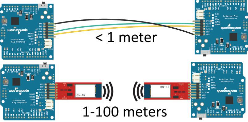
This week I intent to work over blue tooth module. It is a wireless technology standard for exchanging data over short distances usin short wavelength UHF radio waves in the ISM band and ISM band is basically the range of frequencies ranging from 2.4GHz to 2.485GHz. It was first invented by telecom vendor Ericsson in 1994 and was originally conceived as a wireless alternative to RS-232 data cables
The basic advantage of blue tooth technology can be abserved from following communication digram
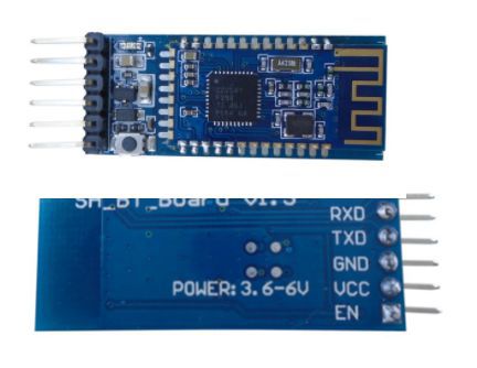
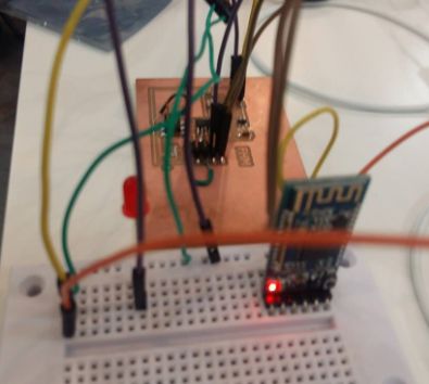
The Bluetooth module I used in this assignment is SH-HC-08
I started configuring this module with both of my boards I developed during week 6 and week 10 one by one and got successful results on both.
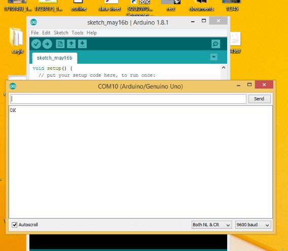
I connected Rx/Tx pins of bluetooth module with Rx/Tx pins of board which were two of pins of FTDI header there and put 9600 baud rate in the program and opened the serial monitor to observe the results using some of the AT commands also. following pictures will demonstart the process step by step
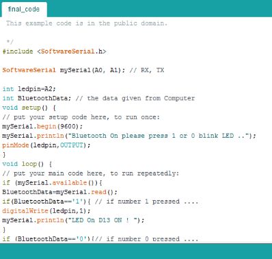
Programming the module
Configuring the device using AT commands
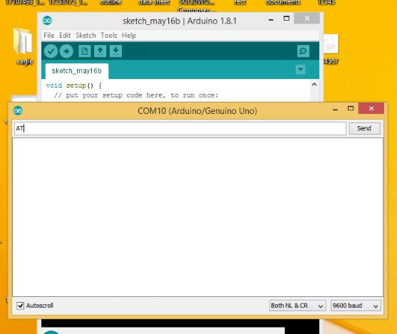
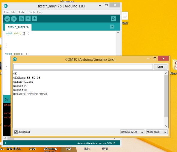
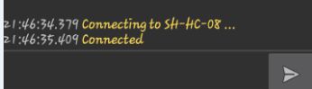
Module response
Other responses of AT commands
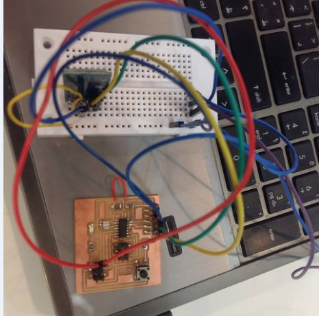
Now I just change the configuration of two pins. I connected RX of board to TX of blue tooth module and TX of the board with RX of blue tooth
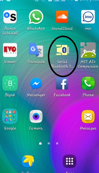
After that I Installed the app Serial Bluetooth Terminal in me android cell phone and prepared the two devices for pairing
Powering up the module and the board
Surffing the app to pair the device
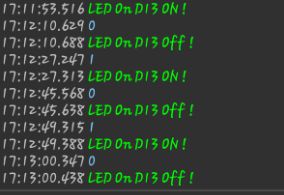
Sending commands from mobile app to blue tooth module
Video demostration of after pairing the devices
I2C Communication
As I was also anxious to extend this assignment to perform communicating my two circuit boards through I2C protocol. As went through this I came to know we can connect almost 120 devices just by using pair of wires collectively called bus topology with good data transfer rate upto 2Mbps. This protocol can be developed by using almost all families of micro controller.
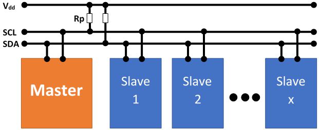
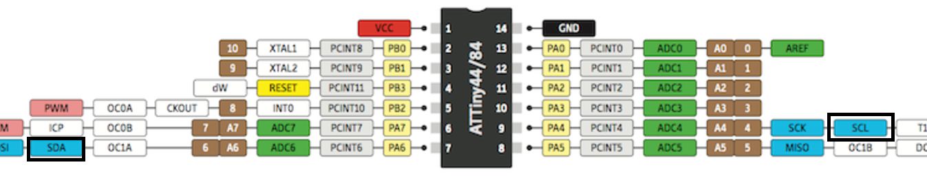
To develop the communication we need to study some basic facts regarding the process like I came to know that there are built in pins for I2C communication in Tiny family boards as i was using ATtiny 44 for both boards to be communicated as slave and I used Arduino as their master. following image is showing the pins which are dedicated for this protocol.
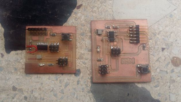
I used Arduino UNO as master device with two slaves. the boards for slave devices I developed during my assignments 6,8 and 10. you can access all the files by jumping to these pages.
As for as pull up resistors are concerned I activate these resistors in my program using this instruction digitalWrite(2,HIGH); . If we are not defining this instruction we have to connect two pull up resistors up to 3 kilo ohm value by connecting one with SDA and VCC and other with SLC with VCC
For developing the code I install the library tinywireS as this seems to be fit for i2c slaves.
Code for master
#include

void setup() {
  Wire.begin();
  Serial.begin(9600);
  pinMode(13, OUTPUT);
  digitalWrite(2,HIGH);
  digitalWrite(3,HIGH);
  //digitalWrite(13,HIGH);

}


char data = 0;


void loop() {
 if (Serial.available()){
  data=Serial.read();
  //Serial.write(data);
  }

  if (data == '8'){
     Serial.write(data);
     digitalWrite(13, !digitalRead(13));
  Wire.beginTransmission(8);
  Wire.write(0);
  Wire.endTransmission();
  delay(200);}

  delay(1000);

  if (data == '9')
  {
         Serial.write(data);
     digitalWrite(13, !digitalRead(13));
  Wire.beginTransmission(9);
  Wire.write(1);
  Wire.endTransmission();delay(200);}
    delay(1000);
}
Code for Slave 1
			#include

#define I2C_SLAVE_ADDR 0x08
#define LED1_PIN 8


void setup(){

pinMode(LED1_PIN, OUTPUT);
TinyWireS.begin(I2C_SLAVE_ADDR); //initialize I2C lib and setup slave address
digitalWrite(LED1_PIN,HIGH);
delay(2000);
digitalWrite(LED1_PIN,LOW);
}
byte byteRcvd = 0x00;
void loop (){

byteRcvd = TinyWireS.receive(); //get the byte from master, returns next byte in received buffer
if (byteRcvd == 0){
digitalWrite(LED1_PIN, !digitalRead(LED1_PIN));
delay(2000);
}
}
Code for Slave 2
			#include

#define I2C_SLAVE_ADDR 0x09
#define LED1_PIN 8


void setup(){

pinMode(LED1_PIN, OUTPUT);
TinyWireS.begin(I2C_SLAVE_ADDR); //initialize I2C lib and setup slave address
digitalWrite(LED1_PIN,HIGH);
delay(2000);
digitalWrite(LED1_PIN,LOW);
}
byte byteRcvd = 0x00;
void loop (){

byteRcvd = TinyWireS.receive(); //get the byte from master, returns next byte in received buffer
if (byteRcvd == 1){
digitalWrite(LED1_PIN, !digitalRead(LED1_PIN));
delay(2000);
}
}
Video Demonstration
Download useful files here