20.- Final Project
Jun 07 - 28
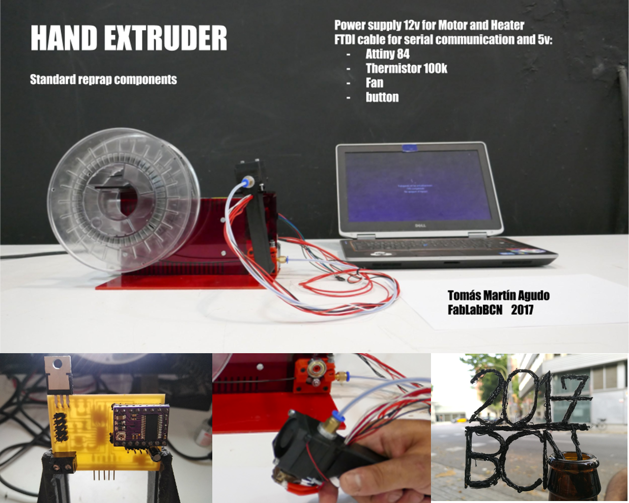
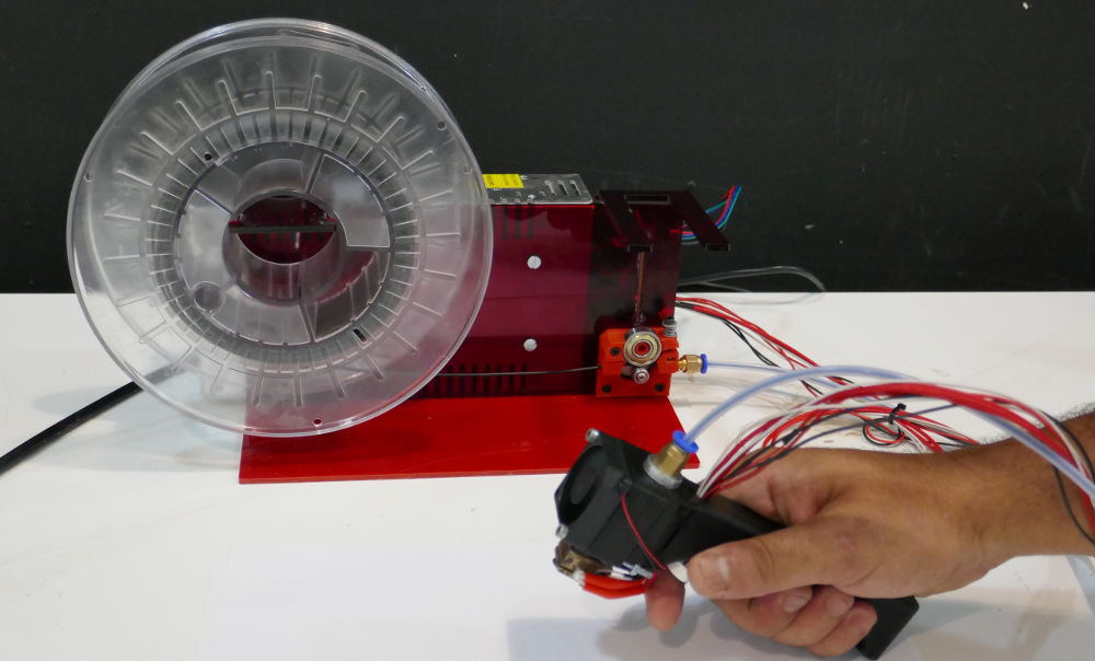
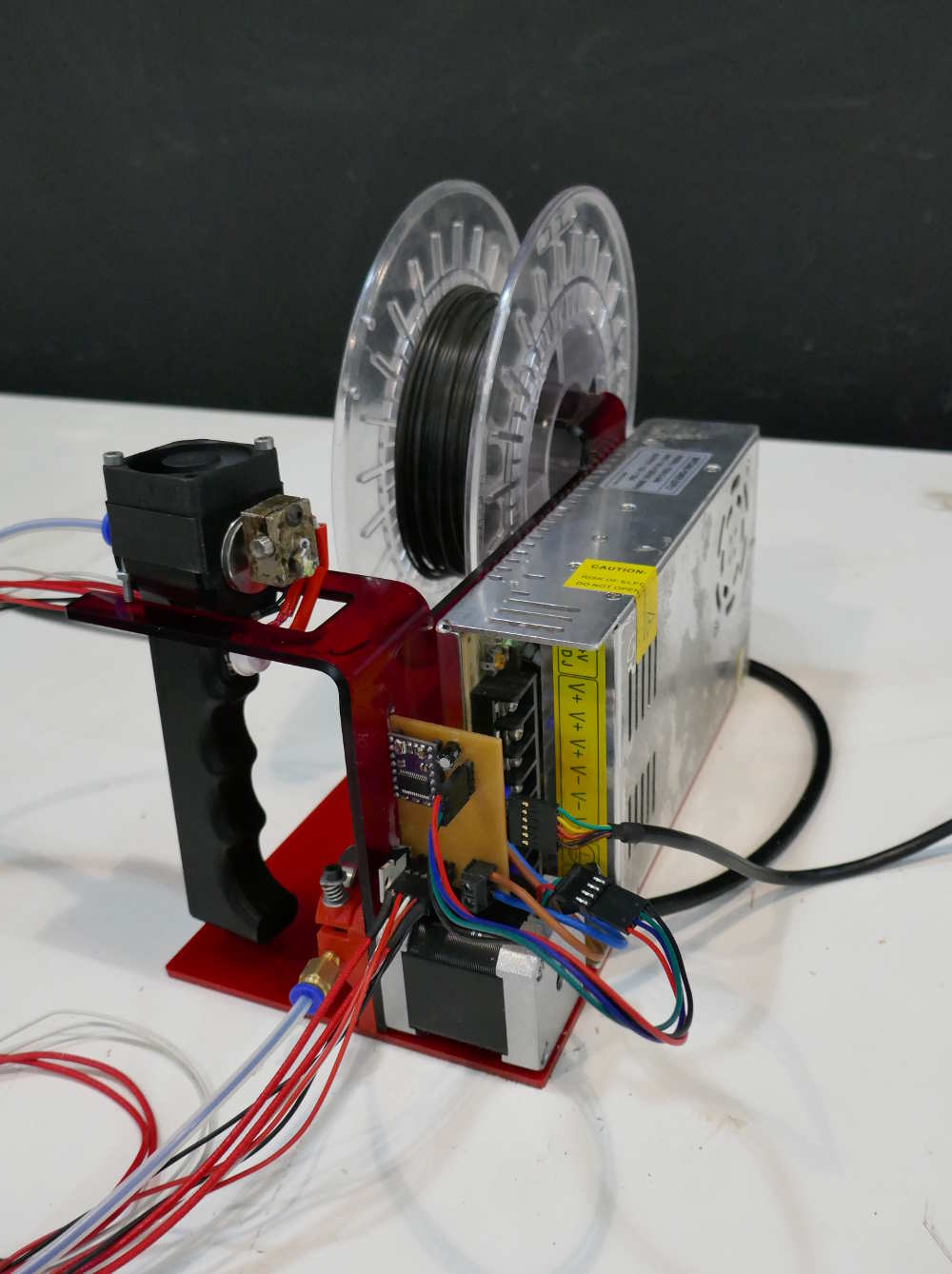
Hand Extruder
- It is a machine that allows you to extrude PLA plastic under the same conditions as a common fdm 3d printer but manually.
- Power supply, motor pushing filament, hot end, motor driver, 1.75mm diameter filament, Hobbed gear are usual replacements of 3d printers from my local fablab.
- Main box and handle are connected together by cables and by a bowden tube for the filament.
Interface and Application Programming(week16)
Applications and implications(week17)
Inventon, intellectual property(week18)
Project development(week19)
Presentation
Bill Of Materials
Electronics
Programing
3D Design (Printing+Laser cuting)
Presentacion
Slide
Video
Presentation
Bill Of Materials.
| element | caracteristics | link | price |
|---|---|---|---|
| Motor | nema 17 | amazon.es | 13Eu |
| termistor | 100k | amazon.es | 1Eu |
| Heater | 12v 40w | amazon.es | 6Eu |
| Fan | 5v 35mm | diotronic.com | 9Eu |
| Hotend | e3dv6 | amazon.es | 9Eu |
| Powersuply | 12V 30A 360W | amazon.es | 15,70Eu |
| Raspberry pi | 3 model b | amazon.es | 38,25Eu |
| Mosfet | N-ch 70a 60v | diotronic.com digikey.es |
2,13Eu |
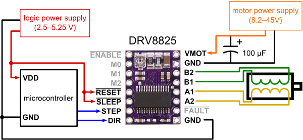
| Motor Driver | DRV8825 | amazon.es | 1,92€ | V Regulator | 5v 1a | digikey.es | 0,49Eu |
Electronics
Thermistor 100k
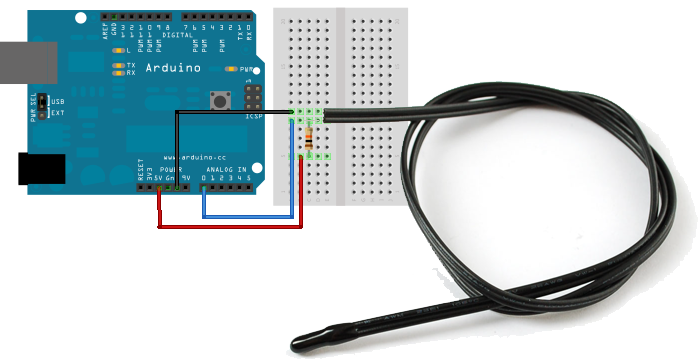
Im using this adafruit tutorial to get into the thermistor
To measure the temperature, we need to measure the resistance. However, a microcontroller does not have a resistance-meter build in. Instead, it only has a voltage reader known as a analog-digital-converter. So what we have to do is convert the resistance into a voltage, and we'll do that by adding another resistor and connecting them in series
I just change in line 2 "#define SERIESRESISTOR 100000" because mi thermistor is 100k. Using the first sketch I got this resulds, when I incrise the temperature with a liter the resistance and the analog reading is decrising.
.png)
.png)
.png)
resulds from the second skech
the problem that I have with this sketch I neet acuarice around 200 C
.png)
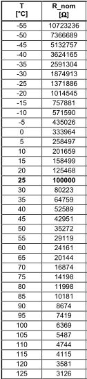
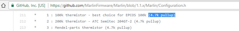
in the program marlin handle this problem with a table of conversion and the pull up resistor 4.7k
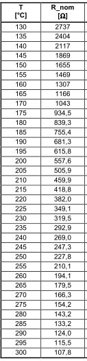
.png)
With the resistance of 4,7k the data of the table of the datasheet and the table of the Marlin firmware correspond with the data of the serial.
Heater and serial
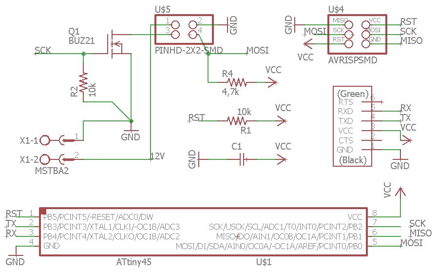
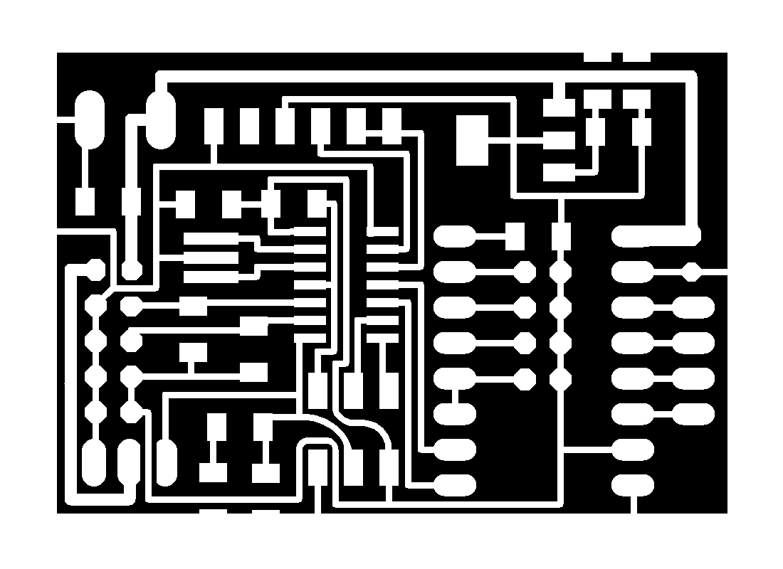
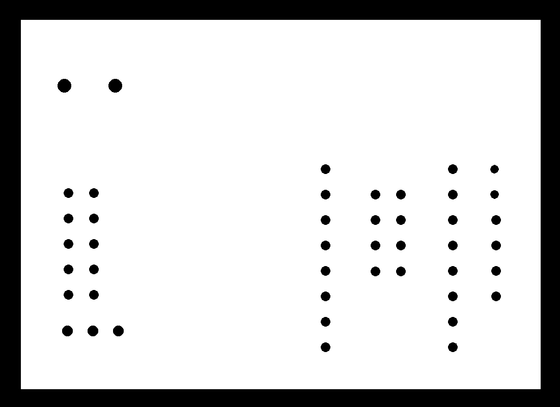
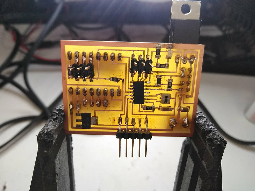
My first intention was to control the temperature by pid and I made a PCB with an attiny 45. I could not make it work because, among other things I was using a type P mosfet that did not correspond to what I had in the code.
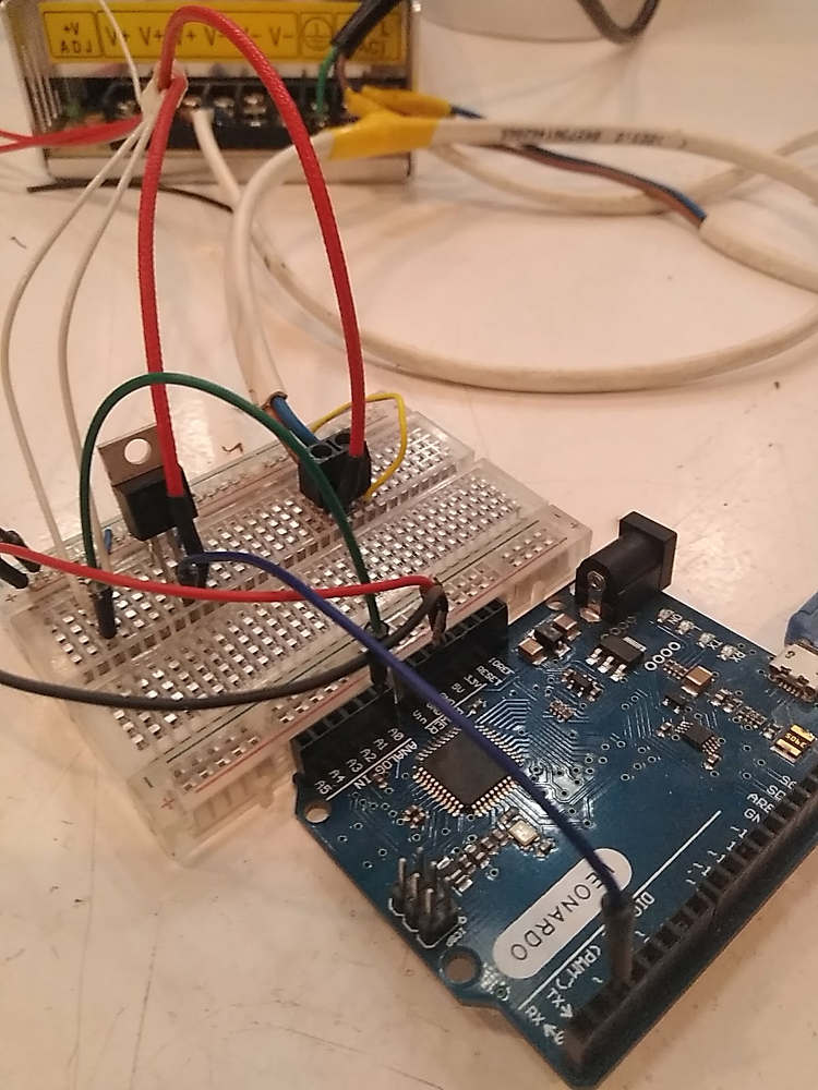

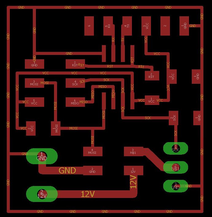
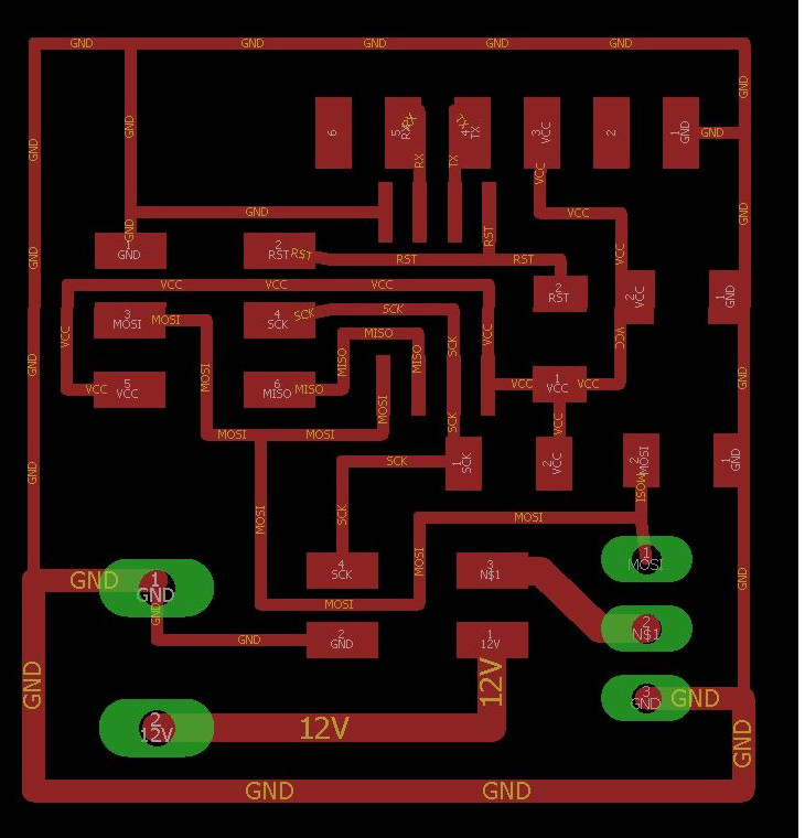
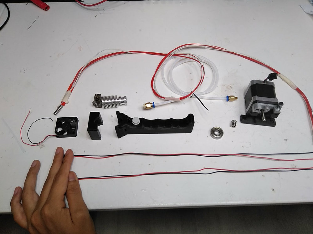
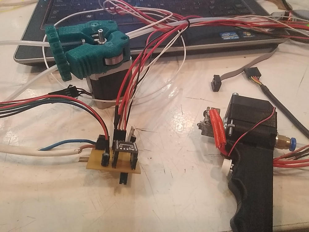
Attempts to integrate all the components

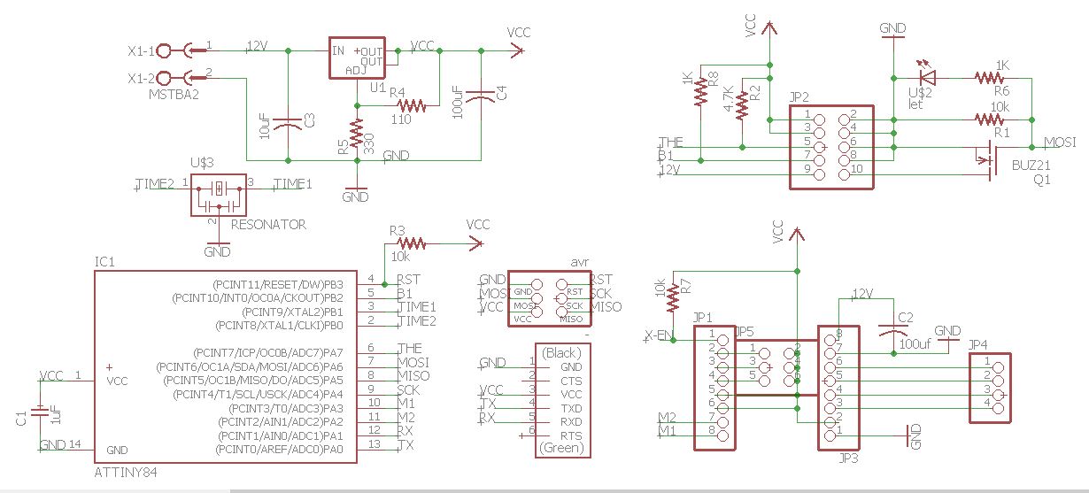
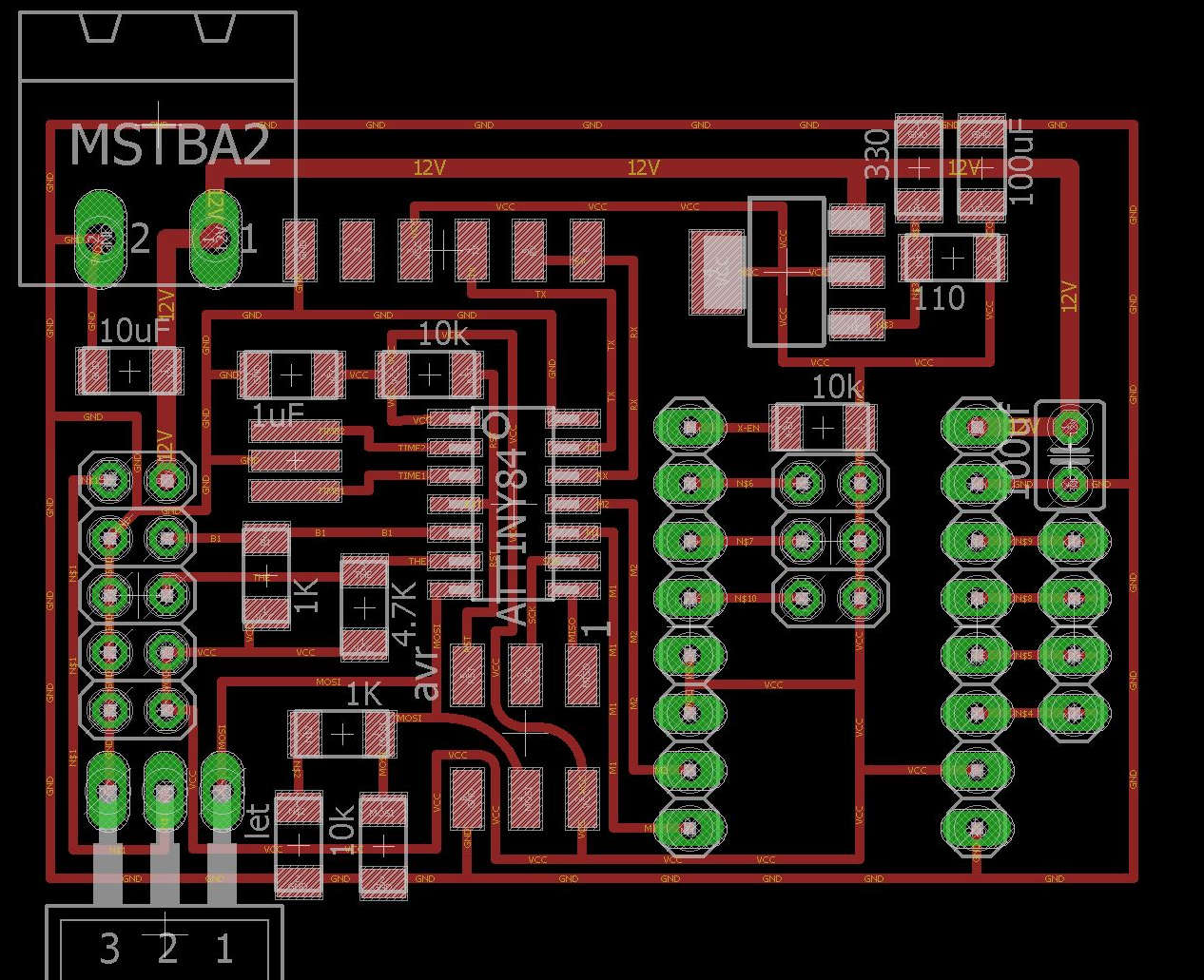

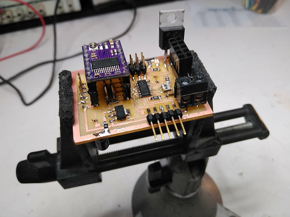
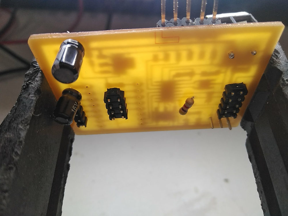
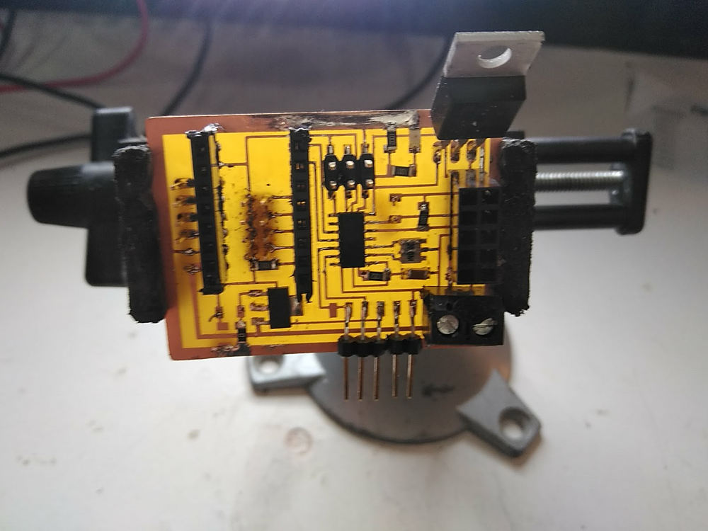
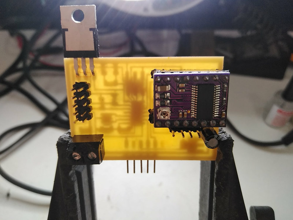
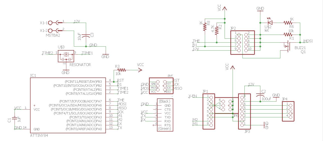
Hand Extruder
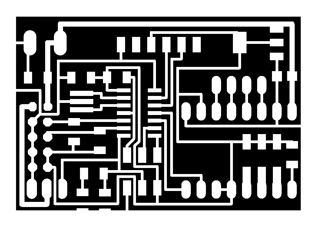
This PCB differs from the previous that no longer has voltage regulator and the resistance of 10k in the pin x-en disables the driver instead of enabling it.
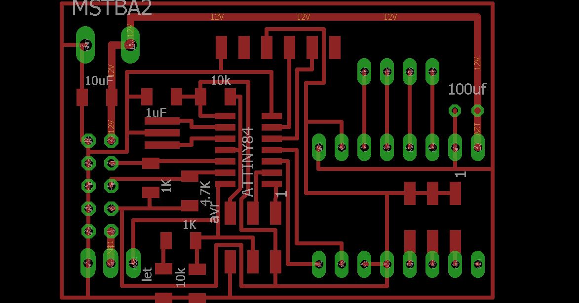
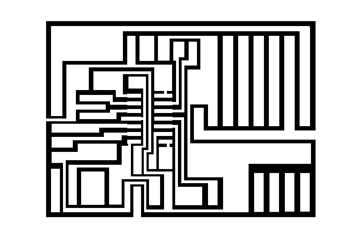
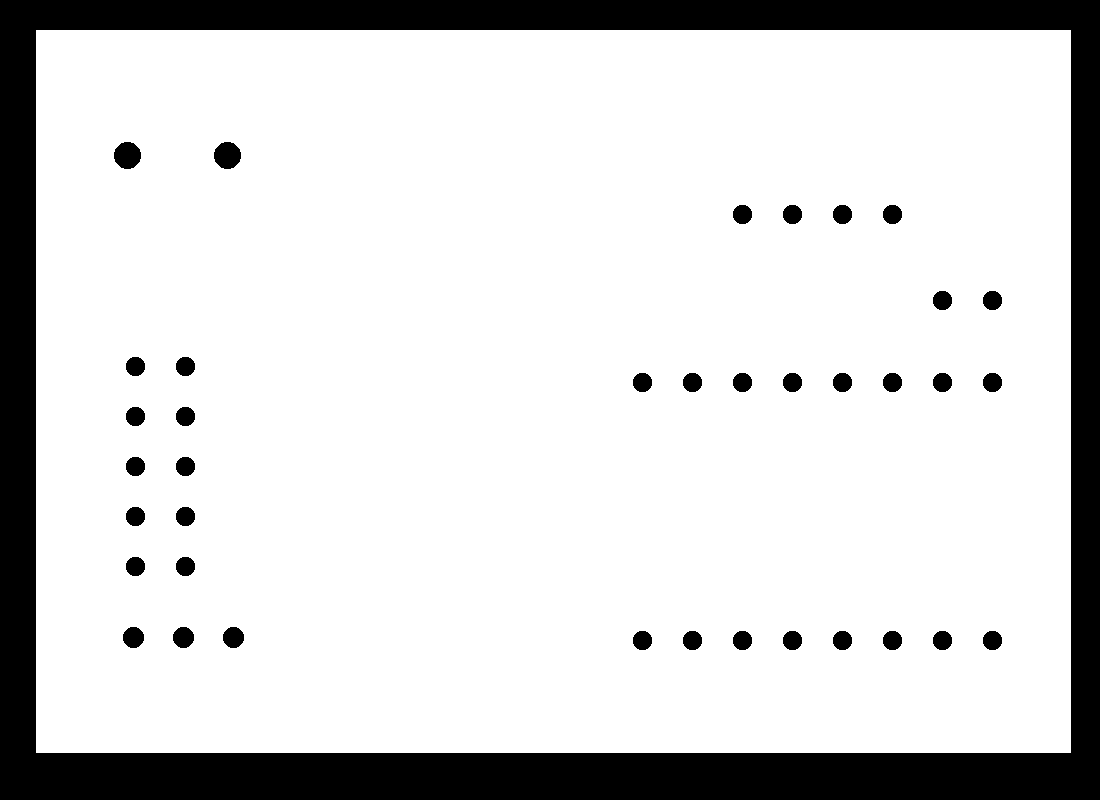
Download the files of this section here : HEagle.zip
Programing
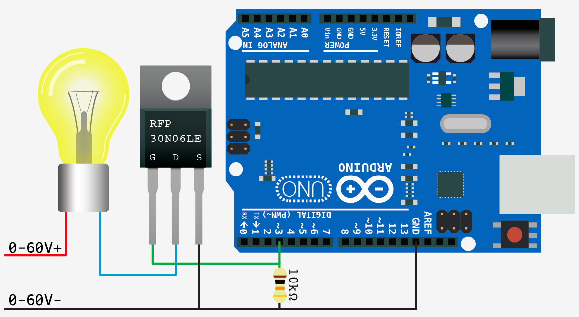
The challenge is to integrate in a single code the functions of thermistor mosfet (heater) motor and button that had tested separately
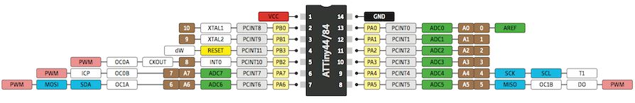
In the first part of the code to integrate the previous codes is not very difficult. Includes the library for the serial and define the name of the pins and variables
#include SoftwareSerial.h

const int rx=0;
const int tx=1;
int i=0;
char buf[12];
SoftwareSerial mySerial(rx,tx);// which analog pin to connect
float temp;

#define PIN_INPUT 7 // THERMO INPUT
#define THERMISTORPIN 7// resistance at 25 degrees C
#define THERMISTORNOMINAL 100000 // temp. for nominal resistance (almost always 25 C)
#define TEMPERATURENOMINAL 25 // how many samples to take and average, more takes longer but is more 'smooth'
#define NUMSAMPLES 5// The beta coefficient of the thermistor (usually 3000-4000)
#define BCOEFFICIENT 4036// the value of the 'other' resistor
#define SERIESRESISTOR 4700
int samples[NUMSAMPLES];

//buton
const int buttonPin = 8;     // the number of the pushbutton pin
const int RELAY_PIN = 6;
int buttonState = 0;         // variable for reading the pushbutton status

//motor
int dirPin = 3;                  // output pin for stepper motor direction
int stepPin = 2;                 // output pin for the pin used to step the motor for your particular motor)
In the setup part the serial port is started, the transmission frequency is indicated and if the pins are to be inputs or outputs and their initial state: HIGH or LOW is indicated too
void setup(void) {

  pinMode(rx,INPUT);
  pinMode(tx,OUTPUT);
  mySerial.begin(4800);

  pinMode(RELAY_PIN, OUTPUT);
  digitalWrite(RELAY_PIN, LOW);
  pinMode(buttonPin, INPUT);
  digitalWrite(buttonPin, HIGH);
  pinMode(dirPin, OUTPUT);       // Assign output mode to pin for direction
  pinMode(stepPin, OUTPUT);
  digitalWrite(dirPin, LOW);// Assign output mode to pin for setp
  digitalWrite(dirPin, LOW);     // Initialize dir pin
  digitalWrite(stepPin, LOW);    // Initialize step pin

   pinMode(THERMISTORPIN, INPUT); // thermo pin
}
In order to co-ordinate the temperature reading via serial I followed the advice of my classmate Sohail and I organize everything related to the serial bus in a separate function that later would call in the main loop.
To get softer data the average is done between 5 readings. The data obtained correspond to the voltage that receives the pin 7, the voltage must be converted to the value of the resistance less than 100k and then corresponds to a temperature.
void comm(void){
  uint8_t i;
  float average;

  // take N samples in a row, with a slight delay
  for (i=0; i< NUMSAMPLES; i++) {
   samples[i] = analogRead(THERMISTORPIN);
   delay(10);
  }

  // average all the samples out
  average = 0;
  for (i=0; i< NUMSAMPLES; i++) {
     average += samples[i];
  }
  average /= NUMSAMPLES;

  //mySerial.print("Average analog reading ");
  //mySerial.println(average);

  // convert the value to resistance
  average = 1023 / average - 1;
  average = SERIESRESISTOR / average;
  //mySerial.print("Thermistor resistance ");
  //mySerial.println(average);

  float steinhart;
  steinhart = average / THERMISTORNOMINAL;     // (R/Ro)
  steinhart = log(steinhart);                  // ln(R/Ro)
  steinhart /= BCOEFFICIENT;                   // 1/B * ln(R/Ro)
  steinhart += 1.0 / (TEMPERATURENOMINAL + 273.15); // + (1/To)
  steinhart = 1.0 / steinhart;                 // Invert
  steinhart -= 273.15;                         // convert to C
  temp = steinhart;
  //mySerial.print("Temperature ");
  mySerial.println(steinhart);
  //mySerial.println(" *C");
}
In the loop, the state of the button is checked.
Then the heater is activated by the condition that the temperature is less than 200 degrees Celsius.
The motor stepper is activated while the button is activated, when the button is on the heater is also activated intermittently to keep the temperature more or less stable because mistras is running while the communication is lost.
Finally the comn () function is called and a small delay is added.
void loop(void) {
   buttonState = digitalRead(buttonPin);

  if (temp < 200) digitalWrite(RELAY_PIN, HIGH);
  else digitalWrite(RELAY_PIN, LOW);

   while (buttonState == LOW)
   {  buttonState = digitalRead(buttonPin);

      digitalWrite(stepPin, HIGH);
      digitalWrite(RELAY_PIN, HIGH);
       //comm();
        delay(1);

      digitalWrite(stepPin, LOW);
      digitalWrite(RELAY_PIN, LOW) ;
        delay(1);
    }
  comm();
  delay(100);
}
Download the files of this section here : check the code
Desing
The design part contains three sections:
1.- The handle, SolidWorks 3d printed.
2.- The frame, rhinoceros lasercut.
3.- Extruder, rhinoceros 3d printed.
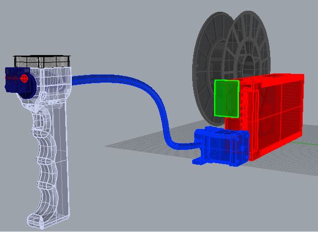
This is the result of the design, system integration.
To achieve a compact and elegant system integration of my project I support myself in a file of rhino with the volumetric components to be able to try different distributions. The modeling comes from grabcad
Download the files of this section here :
Compotition Rhino file
Handle
To design the handle my first idea was to propose a cylinder to be used as a pen but the components are too large and I did not find a distribution that was comfortable to catch.Wim Lanz who is a great lover of graffiti, it occurred to him that the handle could be like a spray can in the way of catching and being activated.
With that idea the components began to fit much more naturally in the handle.
To start designing in SolidWorks the first is to measure the diameter of the hotend and the size of the fan with a Caliper.
The handle has two parts, one to catch it that contains the button and the other part is the fan. The hotEnd is fixed and secure between these two screwed parts.
Download the files of this section here : SW - stl1 - STL2 - Simplify 3d factory file
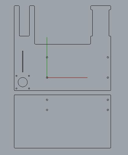
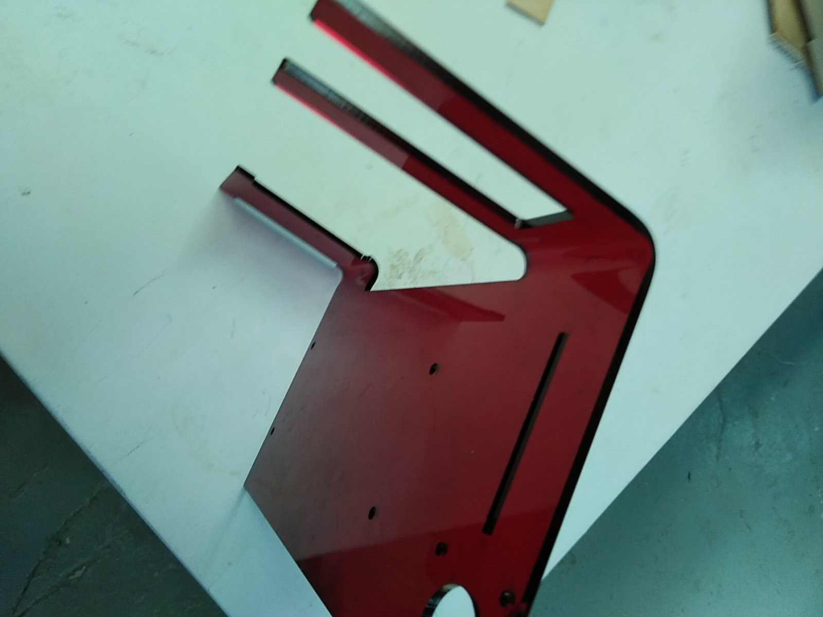
Frame
The frame counts of two pieces, one screwed to the side that contains the rest of elements, and the other one screwed to the base that provides more surface of support to support the weight of the spool.
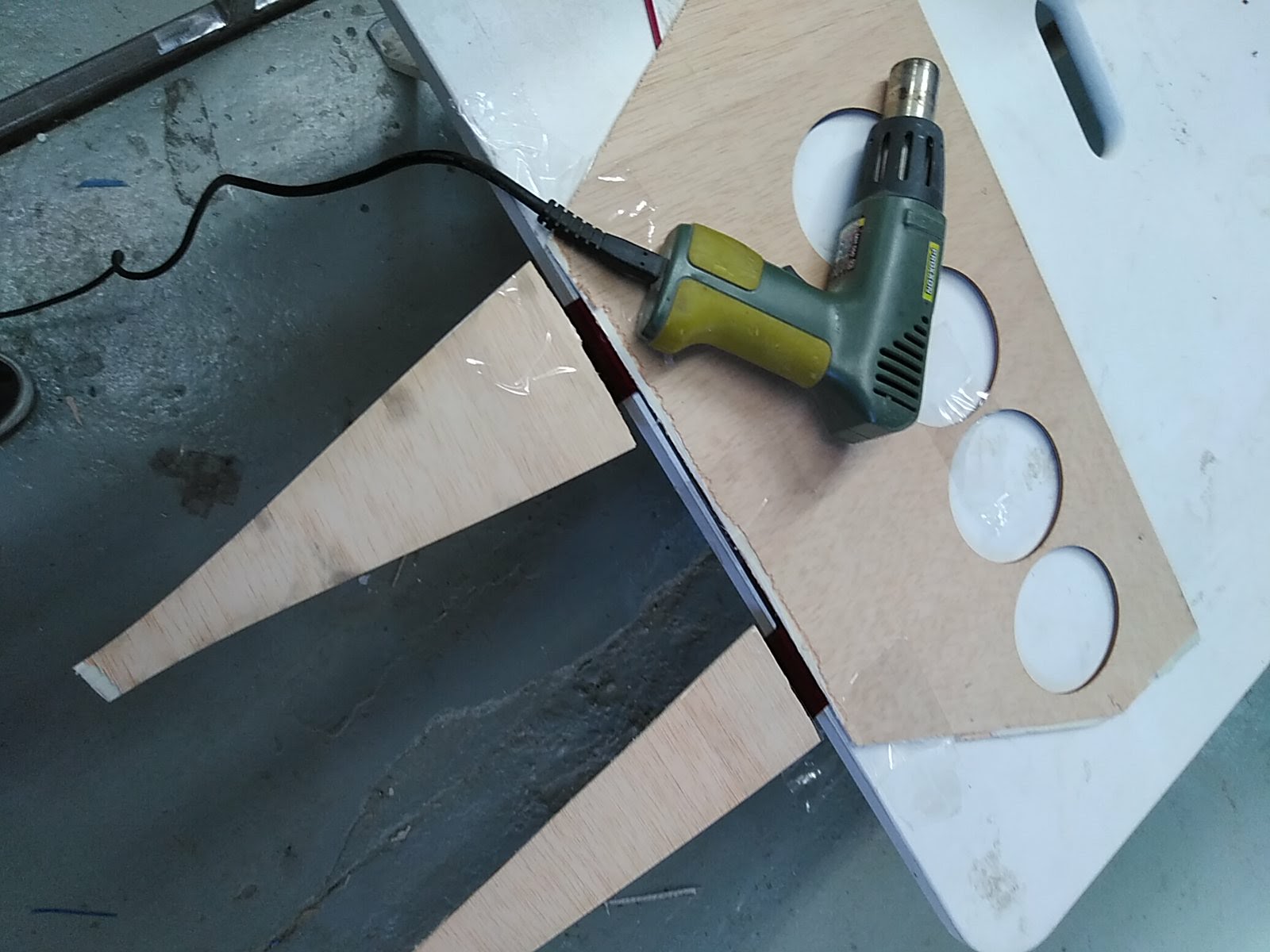
I have approved the M4 screwdrivers of the power supply to design the acrylic frame to screw it directly. At the local hardware store, find M4 10mm long screws with a V-shaped head so that they do not protrude, on the methacrylate it is scraped by hand to house the screw head.
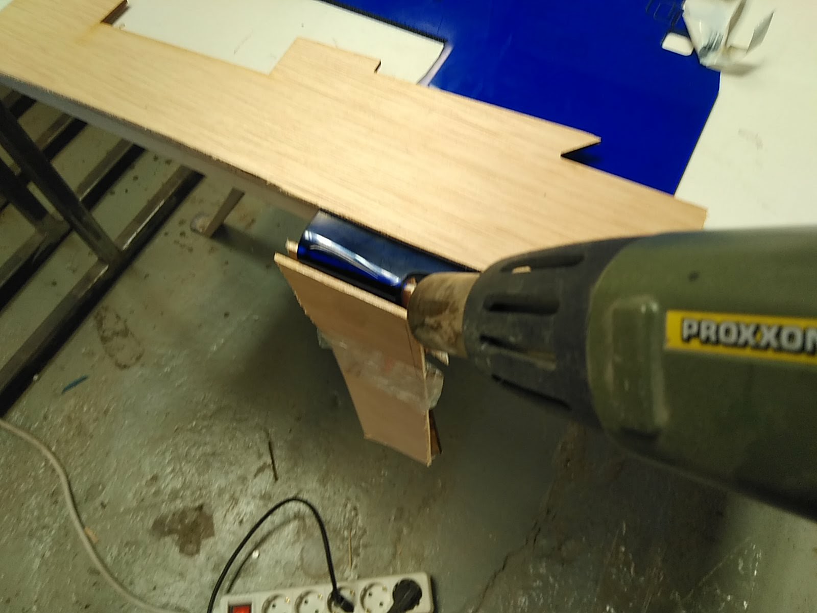
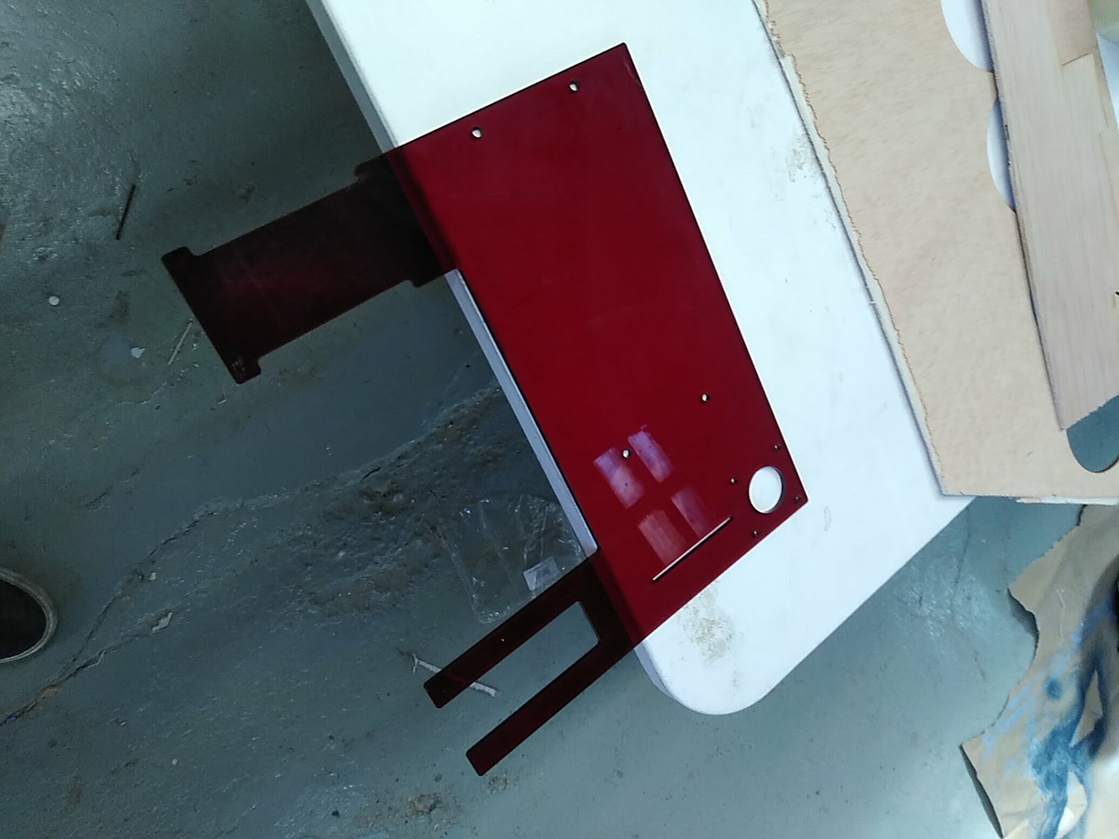
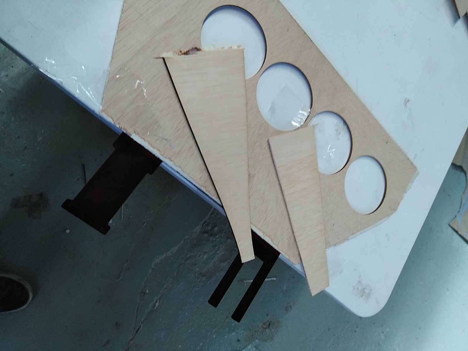
When I came up with the idea of folding the acrylic with a heat gun, I decided to test the result with a surplus (blue piece). The results were satisfactory and I went ahead. I place the acrylic on the edge of the table to guide the crease. The part that will remain straight is covered with scraps of wood to focus the heat on the part to be bent. Once the wood pieces have been fastened with tape the heat is applied gently for about one minute. When the acrylic is sufficiently hot it is malleable for a time to be able to correct the shape of the fold
Download the files of this section here : lasercut Rhino file
Extruder
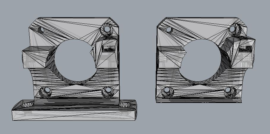
The piece in charge of extrude the obtained from thingiverse and I modified it because I did not need the protrusion to hold it. The motor is attached to the extruder adaptor with the methacrylate between both of them.
drag and drop STL to rhino
The file is an STL ie a mesh and rhino is not the best program to handle mesh even so manage to get a mesh closed with the following commands."ExtractMeshFaces""FillMeshHole""CollapseMeshFace"with "pointsOn"(f10)and"poindsOff"(f11)Enable or disable mesh vertices in order to modify them, With these commands and the help of the lateral views it is possible to make simple modifications in STLs.To finish using "repair mesh" to check if everything is correct.It is also useful "show edges" to locate naked edges
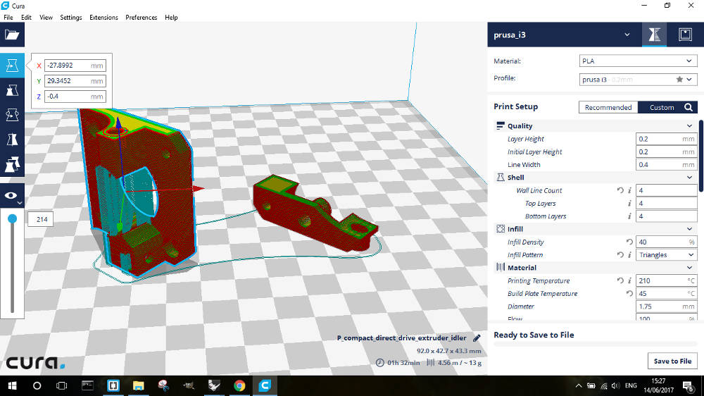
Export selection as a STL again make the slice in Cura
The pieces have this orientation because the orientation of the layers does not detract from the efforts that the piece receives. Also 40% of infill helped make it more resistant.
Download the files of this section here : Extruder Rhino file - ExtruderBody STL file - ExtruderArm STLarm file
