08.- Embedded programming
Mar 15
Assignments:
- Read a microcontroller data sheet
- Program your board to do something, with as many different programming languages and programming environments as possible
- Extra credit: experiment with other architectures
- Read a microcontroller data sheet
- Program arduino leonardo with Arduino IDE
- Program the echo hello-world (ATtiny44)) with Arduino IDE
- Code: Debounce.ino
- Case
Read a microcontroller data sheet
During the lecture I realized that the datasheet should be read as a reference guide. It can not be read as book is better to skim through, just to know what the components are and some specifications, to get an idea of what you can find there. And come back later as your knowledge grows.
The data sheet is a new document for me and what I would like to learn during this course is simply how to know what to look for and where to find it when a problem arises. Also I would like to understand why certain pins have a specific use and also I intrigue much the operation of the internal clock that differentiates it means to pointer an external clock.
Program arduino leonardo with Arduino IDE
To become familiar with the arduino language program first my arduino leonardo With buttom and debounce
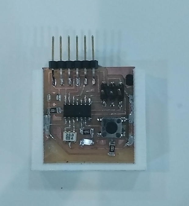
Program the echo hello-world (ATtiny44) with Arduino IDE
To start we need the drivers for the FTDI cable and install the Attiny arduino library.
We had guide document and higtlowtech available.
To install the library go to tools, preferences and pasted this link on additional boards manager url.
https://raw.githubusercontent.com/damellis/attiny/ide-1.6.x-boards-manager/package_damellis_attiny_index.json
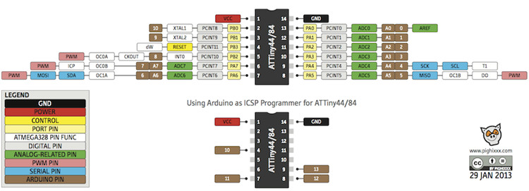
It is important to know the equivalence of ATtiny pins to Arduino pins, as the Arduino IDE works with Arduino board pins.
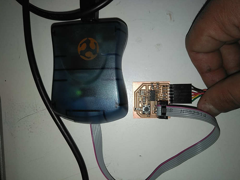
To program the board I have connected the AVRISP MKII programmer and the FTDI cable from my laptop to the PCB. Care must be taken to connect the cables with the correct polarity, in this case the red cable of the programmer indicates the GND.
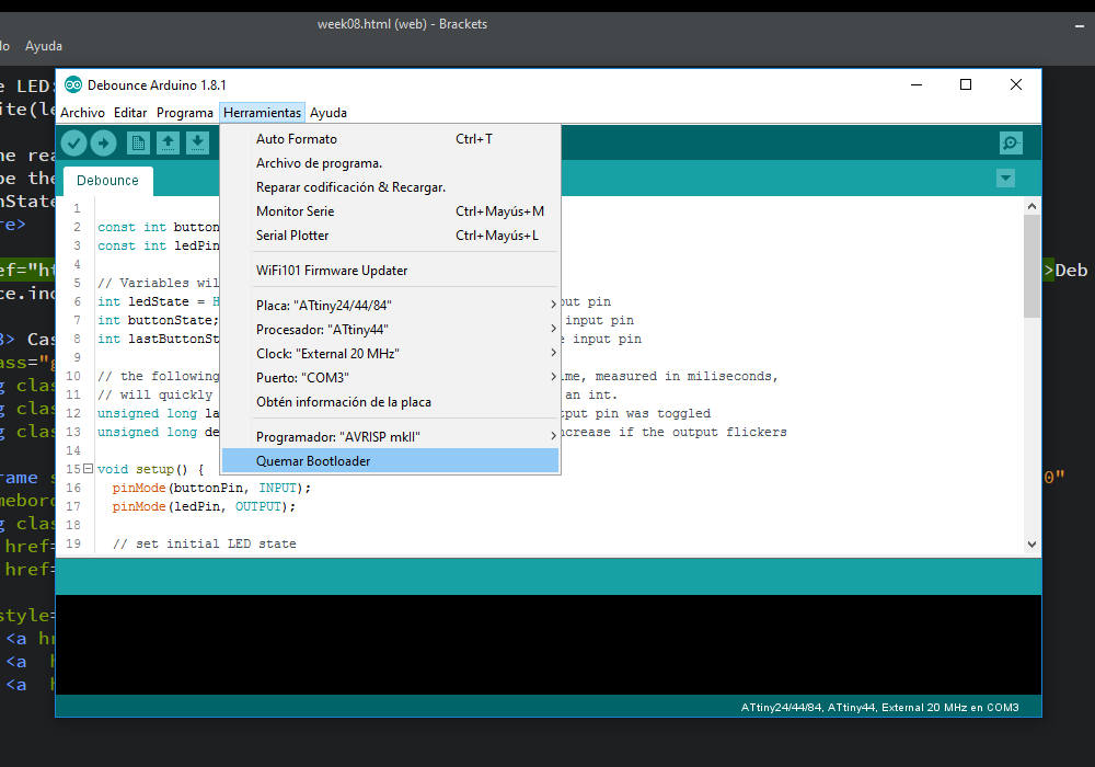
Once they were connected to the computer I selected the right options on Arduino IDE.
- Board: ATtiny 44
- Processor:ATtiny 44
- Clock: External 20Mhz
- Port: COM 3 (to see wich one it it, it is showed on Window's Device Manager)
- Programmer: AVRISP MKII.
I have not used fabisp because I had difficulty making it work on my windows.
Code: Debounce.ino
This code comes from the examples of Arduino and only one must change the number of the pin to correspond with the pins of Attiny 44.
Each time the input pin goes from LOW to HIGH (e.g. because of a push-button
press), the output pin is toggled from LOW to HIGH or HIGH to LOW.
There's a minimum delay between toggles to debounce the circuit (i.e. to ignore
noise).
const int buttonPin = 8;   // the number of the pushbutton pin
const int ledPin = 7;      // the number of the LED pin

// Variables will change:
int ledState = HIGH;         // the current state of the output pin
int buttonState;             // the current reading from the input pin
int lastButtonState = LOW;   // the previous reading from the input pin

// the following variables are unsigned long's because the time, measured in miliseconds,
// will quickly become a bigger number than can be stored in an int.
unsigned long lastDebounceTime = 0;  // the last time the output pin was toggled
unsigned long debounceDelay = 50;    // the debounce time; increase if the output flickers

void setup() {
  pinMode(buttonPin, INPUT);
  pinMode(ledPin, OUTPUT);

  // set initial LED state
  digitalWrite(ledPin, ledState);
}
Here the key is "millis ()"that Returns the number of milliseconds since the Arduino board began running the current program. This number will overflow (go back to zero), after approximately 50 days.
You get the status of the button I is stored in "int reading".
The first condition says that if the current state of the button does not match the previous state, the variable "lastDebounceTime" is updated with the value containing "millis ()".
The following condition allows the following condition if the state change of the button has occurred in more than 50 milliseconds.
Only toggle the LED if the new button state is HIGH.
void loop() {
  // read the state of the switch into a local variable:
  int reading = digitalRead(buttonPin);

  // check to see if you just pressed the button
  // (i.e. the input went from LOW to HIGH),  and you've waited
  // long enough since the last press to ignore any noise:

  // If the switch changed, due to noise or pressing:
  if (reading != lastButtonState) {
    // reset the debouncing timer
    lastDebounceTime = millis();
  }

  if ((millis() - lastDebounceTime) > debounceDelay) {
    // whatever the reading is at, it's been there for longer
    // than the debounce delay, so take it as the actual current state:

    // if the button state has changed:
    if (reading != buttonState) {
      buttonState = reading;

      // only toggle the LED if the new button state is HIGH
      if (buttonState == HIGH) {
        ledState = !ledState;
      }
    }
  }

  // set the LED:
  digitalWrite(ledPin, ledState);

  // save the reading.  Next time through the loop,
  // it'll be the lastButtonState:
  lastButtonState = reading;
}
Download the files of this section here : Debounce.ino
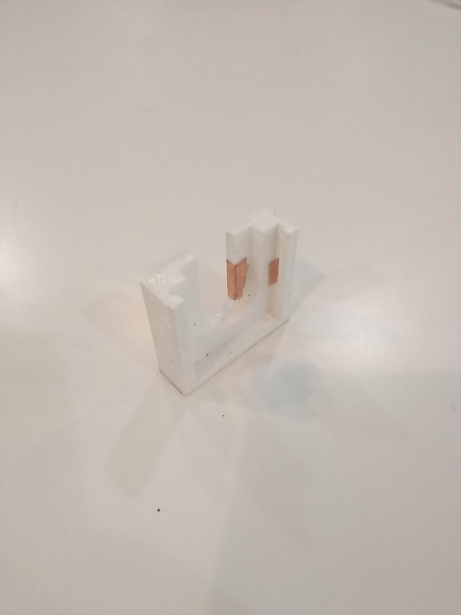
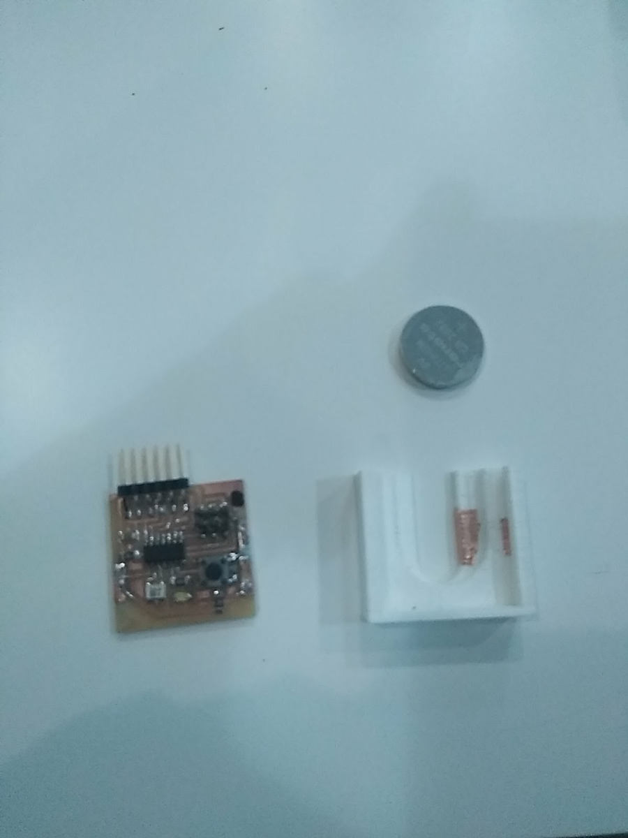
Case
When the assignment was finished I was impressed with the potential that has program microcontrollers integrated in PVC designed by you although it was something simple as a button and a led and I wanted to put a battery to show it to people.
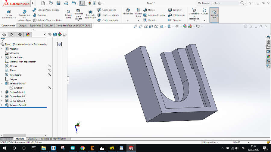
The challenge was to connect a button battery between VCC and GRN. On the board grn and vcc are on the sides and I connect them by sticker copper on a 3d printed case.