03.- Computer-controlled cutting
Feb 08
group assignment:
-make laser cutter test part(s), varying cutting settings and slot dimensions
individual assignment:
-cut something on the vinylcutter
-design, make, and document a parametric press-fit construction kit,
accounting for the laser cutter kerf, which can be assembled in multiple ways
Lasercutter test
Stikers rubiks cube
Parametric press-fit
Laser cut frame
Laser cutter test
First, we must give actual dimensions to the file. We will work on mm, to change this setting, we go to FILE, DOCUMENT PROPERTIES. There we can change the units and the board size. Once we know we are working on mm, we draw a rectangle. On the top of the screen we have the description of the rectangle.
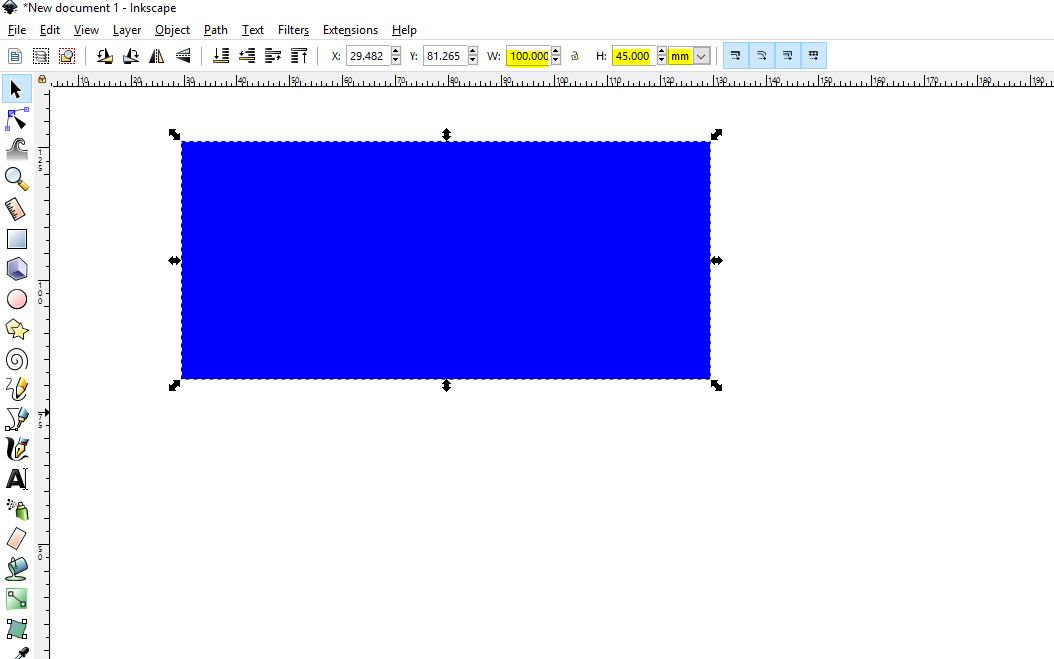
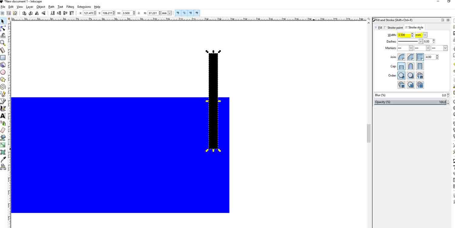
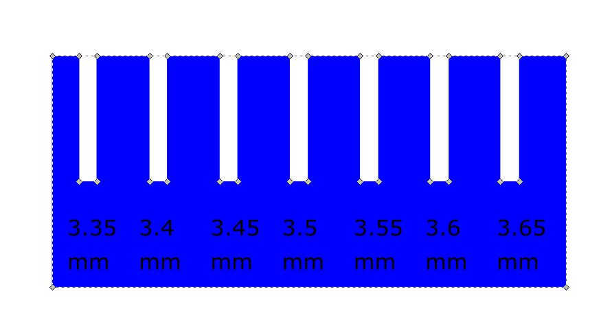
In this case, we gave it a 100x45 mm dimension. Now we draw a straight line, and give it a stroke of 3.5 mm (We want to do the test with 3.5 mm cardboard). Now we copy the line a few times. To align the lines evenly, Inkscape has an Align & Distribute Objects tool, that is very handy. Afterwards, we are going to add some text with the description of each slot. We align them with the lines we have made.
Now we only need to change the stroke of the lines and update the number on the text individually for each one. This is something that would be much easier with a parametric tool, but Inkscape is not parametric so we have to change it manually on each line and text. Now we only must do a subtraction Boolean and export to Rhino. We must export to Rhino because our laser machines' software is Rhino based. Before doing the Boolean, we must transform the lines into paths, it wouldn’t work otherwise. Also, we must transform the number to paths if we want Rhino to recognize them.
Once we have the geometry we save it and send it to the computer controlling the laser. And after updating the settings we can send it to the laser. Our laser works with colors. We must change the color depending on the order we want the laser to do the cut. We wanted the numbers to be engraved and the rest to be cut so we only needed two colors. It is always easier to work with absolute colors. We used red and blue. After the colors are set, the important step is to set the speed and power the machine will use for each of them. This might get a couple tries to get it right. Here, we recorded a video as our mentor was teaching how to use the machine. We experienced the catching on fire Neil talked about on Monday. Apparently it is not unusual and that is why you have to be watching while the machine is doing something.
.JPG)
.JPG)
Download the files of this section here Laser fit test files.rar
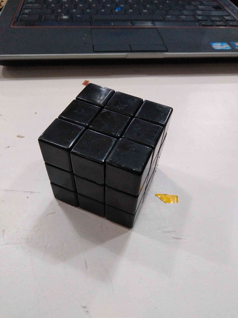
Stickers rubiks cube
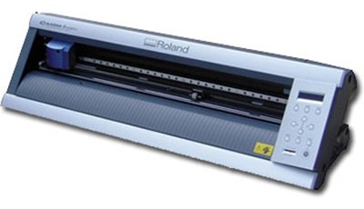
For the vinyl cutting exercise I have decided to put new stickers on my old rubik's cube using Vinyl cutter GX-24 Camm Servo.
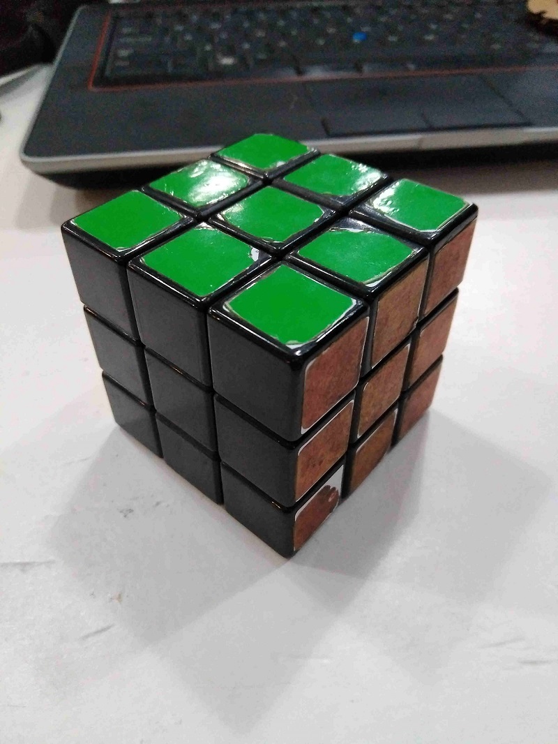
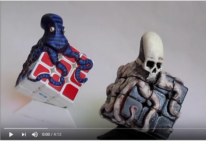
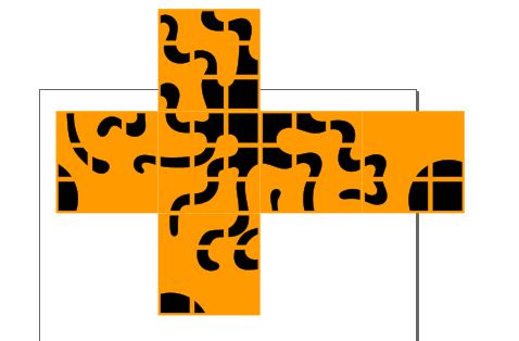
Instead of making normal stickers of a color for each face I have taken the idea of the designer Eduardo Mendoza Octopus attack puzzle to do something similar to all stickers of the same color
youtube canel
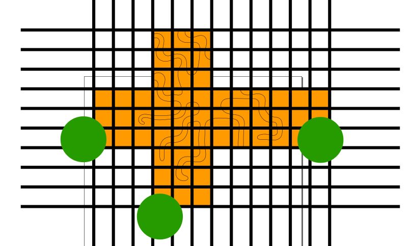
I have used inkcape in order to make the design
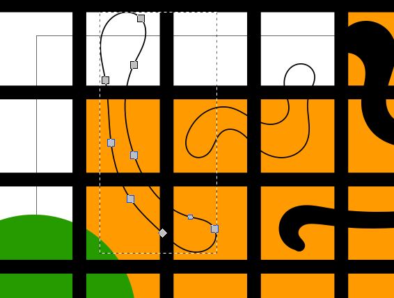
I made a grid to create the cells of each sticker,
All the lines of the grid are clones of a line to be able to define its thickness quickly,
The drawing of the octopus is done with closed spline,
To be able to do the Boolean operation I have converted the lines of the grid in
Rectangles and I have grouped it
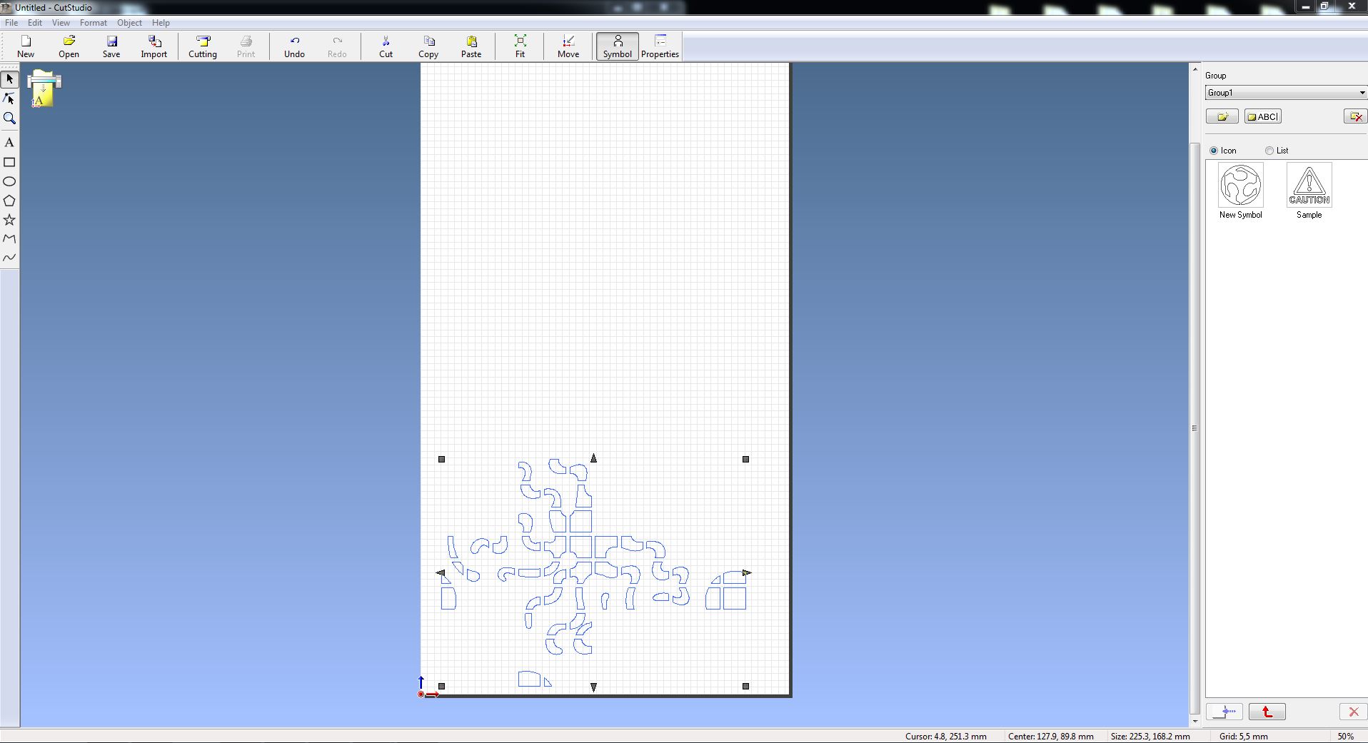
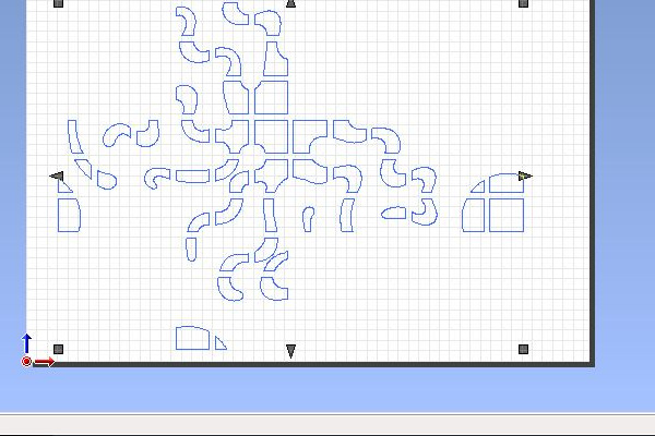
I have copied and pasted the path line from inkscape to CutStudio software and sent to cut to roland with white vinyl
The work flow with the vinyl cuter machine is explained here .
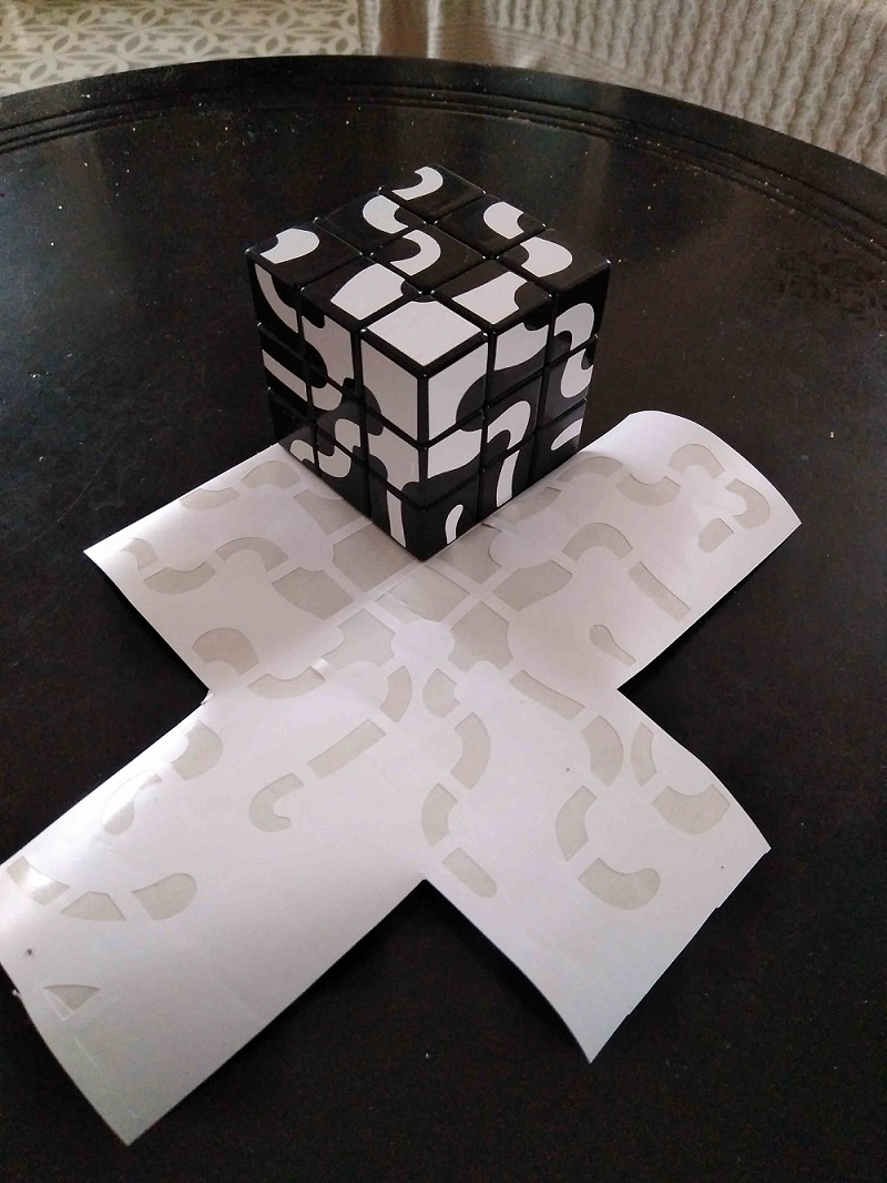
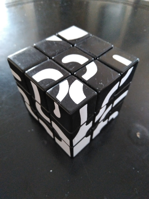
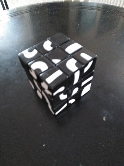
I'm happy with the result although I'm only able to solve the cube looking at the pictures, in addition you have to take into account that the centers have orientation
Download the files of this section here stikers.svg|stikersfinal.svg
Parametric press-fit
This exercise is done with Epilog Laser Cutter.
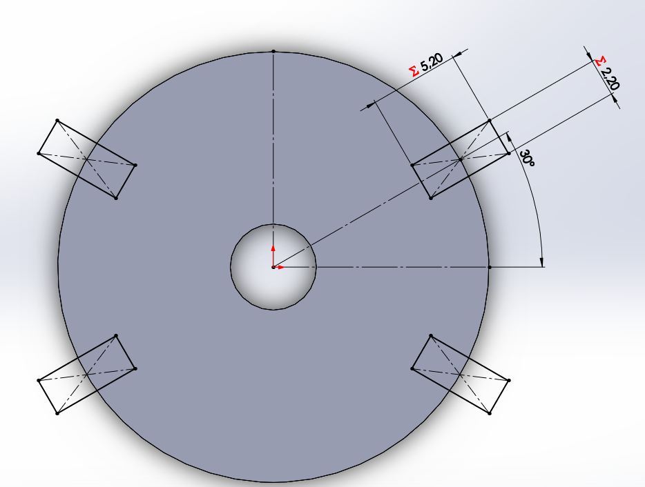
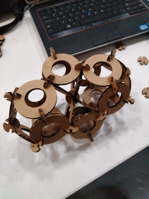
For the press-fit construction kit exercise I wanted to recreate the systems of filling the space with tetrahedra and octahedrons
I used solidwords to create two pieces, one represents the face and has three slots at 120 degrees the other represents the edges and has four slots at 1.23 rad and 1.91 rad which are the angles between the faces of the tetrahedron and octahedron
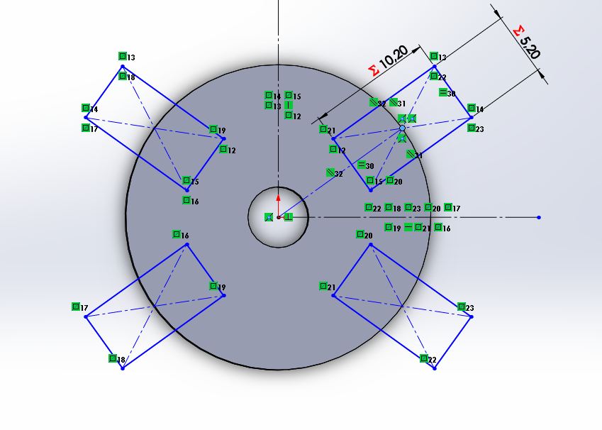
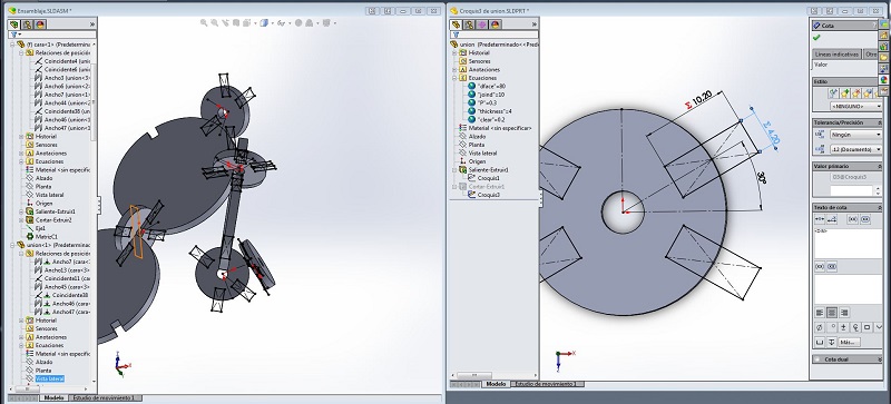
As you can see in the video I made a .txt file that contains the parameters of: Face diameter, slot size, material thickness, tolerance and proportion between piece
To create this txt you have to work with equation manager, then click on export and choose the type of file.
The good thing is that the same text document serves parameters to post different SW files
.png)
.png)
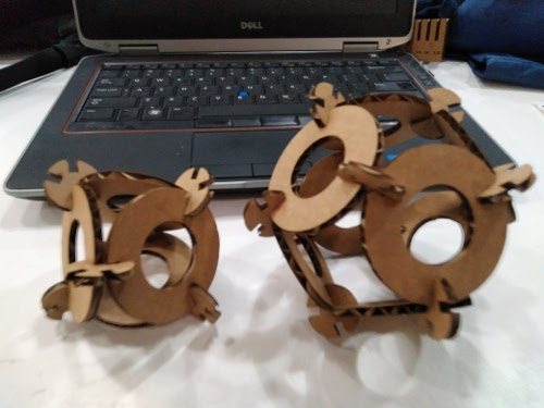
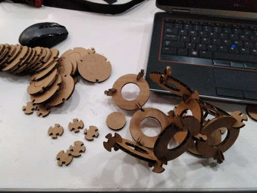
I've needed a couple of attempts to get the consistency I wanted but at the end I have achieved a fairly solid structure.
According to my experience the required tolerance for carton and for single-lace joints is 0. the carton is soft and my pieces separate easily
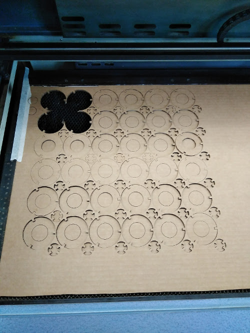
I used 4mm cardboard and speed: 100%, power: 100%, frq: 400
Download the files of this section here union.SLDPRT|cara.SLDPRT|Ensamblaje.SLDASM| nesting.3dm|parametros.txt| repository
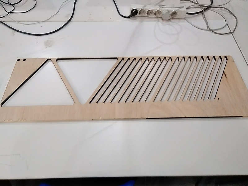
Laser cut frame
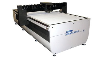
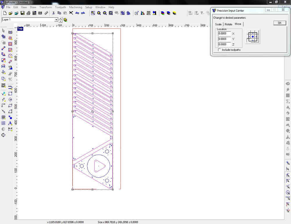
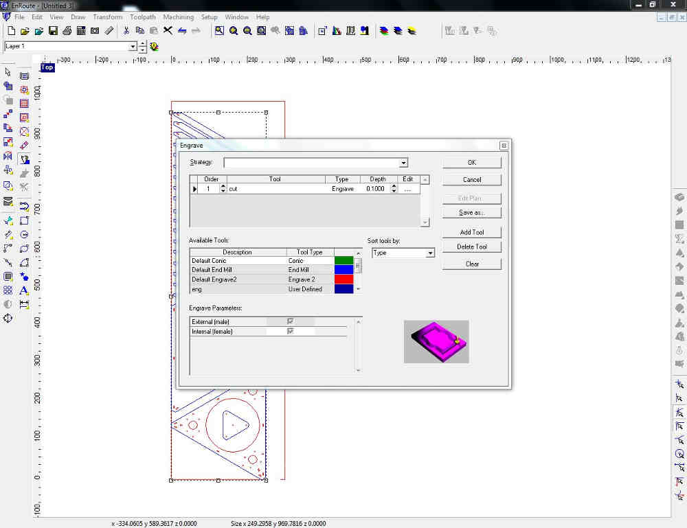
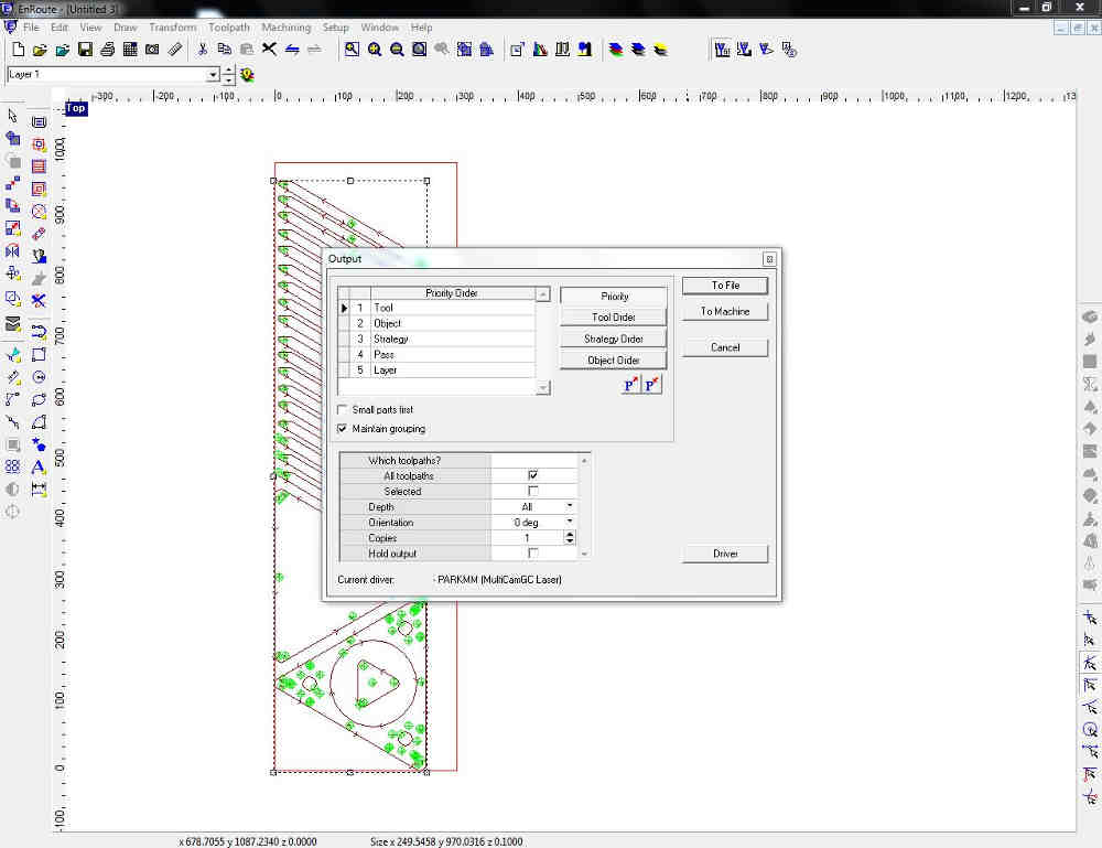
For my final project I did the prototype of the frame with Multicam Laser Cutter.
It is these images I explain the process to create the code for multicam step by step.
This exercise is related to prototype final project.
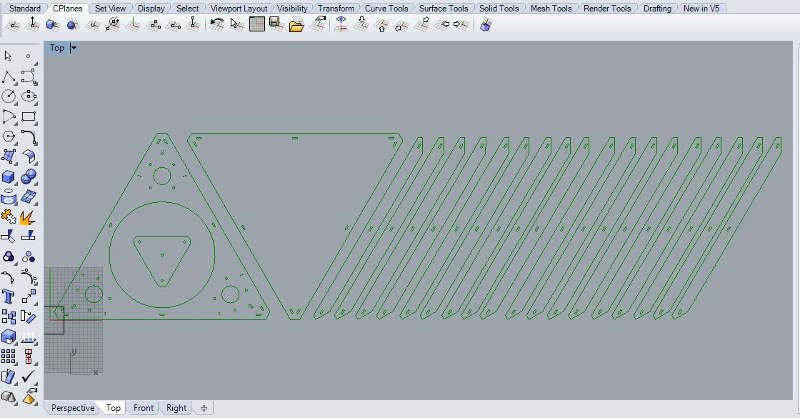
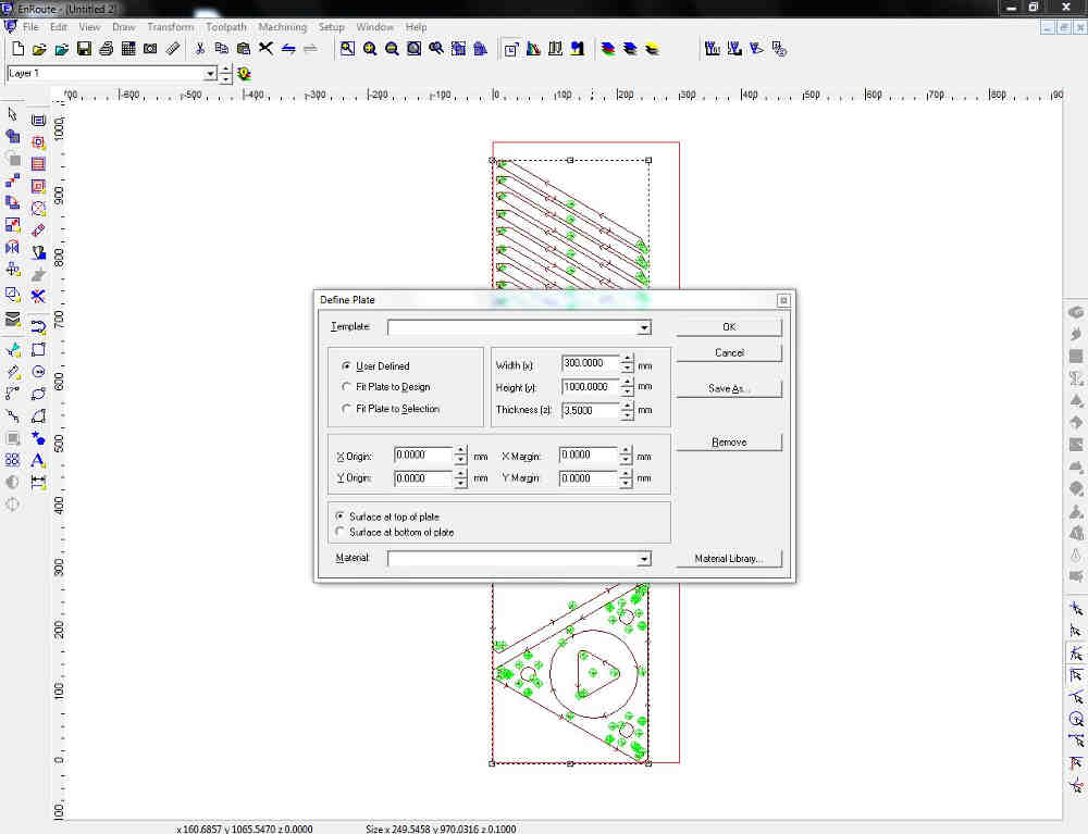
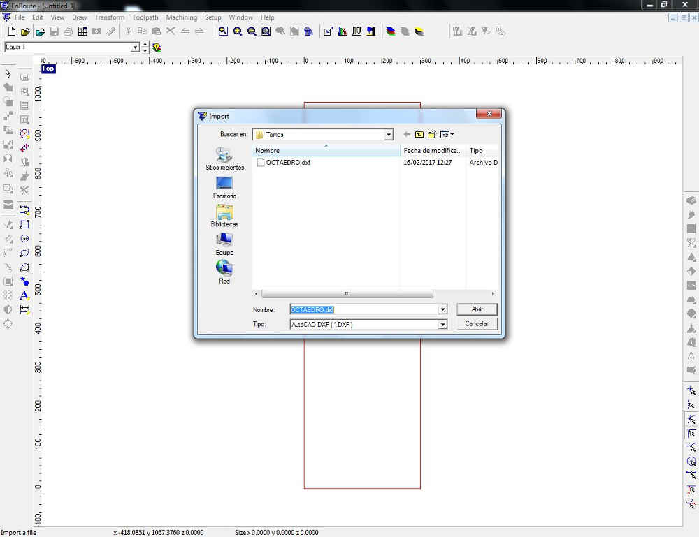
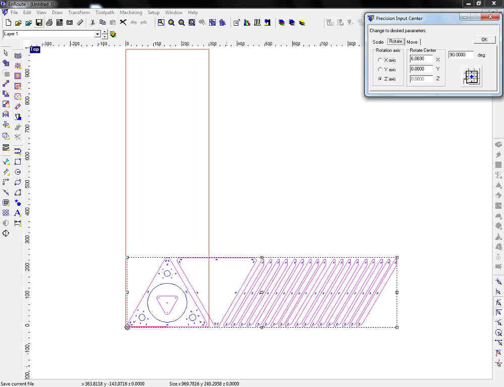

Download the files of this section here OCTAEDRO.dxf
