15. NETWORKING AND COMMUNICATIONS
INTRODUCTION
The goal of this assignment is design and build a wired and/or wireless network connecting at least two processors.
Students should have:
Described your design and fabrication process using words/images/screenshots
Explained the programming process/es you used and how the microcontroller datasheet helped you
Outlined problems and how you fixed them
Included original design files and code
Electronics design
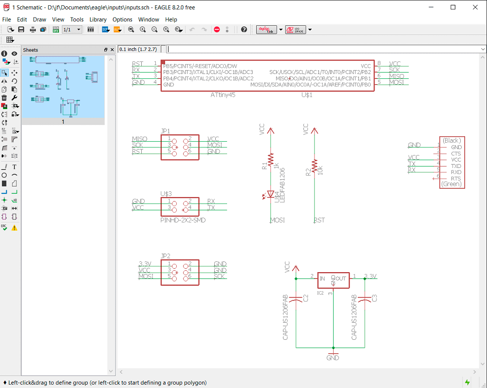
First of all, I need to do the board, in the week 06: electroncis design I explained how to use the Eagle. For this board, I took the Neil's board and I made some changes, first of all the microcontroller that I use, was the Attiny85. Also I change the TX and RX to do a better design, and I put two headers, one to program the microcontroller (VCC, GND, MOSI MISO, SCK, RST) and another one which has some pins in common, in this way, I can connect two sensor in this board. Moreoveer I put the header for the FTDI.

After the schematic, I did the board.

I did the 'CAM Processor...' and I saved the board as a 'eps' (only the 'Top', 'Vias' adn 'Pad'), and with photoshop I generated the 'png' files. With them I generated the two 'rml' files with the FabModules (as the week 04: electroncis production) and I did the board with the milling machine. When it finished, I weld the different components.
Program
To upload the Neil's program I used the FabISP that I made on week 04: electronics production, I connected it with the board, and with Arduino, where I chosen, the Board: Attiny, Processor: Attiny85, Clock: 1 MHz (later I changed to 8MHz) and Programmer: USBtinyISP. Previously, on Neil's program I changed the TX and RX pins, because I inverted on my design and the line where is #define node_id '0', in this ocasion i put '0' on the first board, '1' on the second, and '2' on the third one.
The firsts times that I programmed the boards, I had not changed the TX and RX pins, and for this resason it did not work, later I remember and I changed, and this was the result, when I entered a number, all the LEDs blinked.
As I was running out of time, I decided to do my own program because I will use in my project, the first board (LDC) will show the values of the second and the third board (temperature and humidity sensor). I tried to do a program for the LCD which has to read the values for the port Serial and showed in the LCD, and a program for the temperature and humidity sensor, which has to write the values of the temperature and humidity for the Serial when it receives for the port Serial its id.
I had some problems because I did not obtain the values correctly, I had to modify a little bit the program but it was not enough, has we can see at the end of the video there was a little bit of noise, this I suppose that was because the wire for the networking was too big, but I decided not to cut it because in the future I want to put more boards, I decided to put a resistence of 10k between the TX(of inputs; or RX of outputs ) and GND to remove this noise.
DOWNLOAD FILE:
week 15 (RAR)


