


04. ELECTRONICS PRODUCTION
INTRODUCTION
The goal of this assignment is learn how to use the milling machine, how to weld the different components and how to programm the FabISP.
Students should have:
Shown how you made and programmed the board
Explained any problems and how you fixed them
Included a 'hero shot' of your board
FabISP
Preparing the documents for the machine
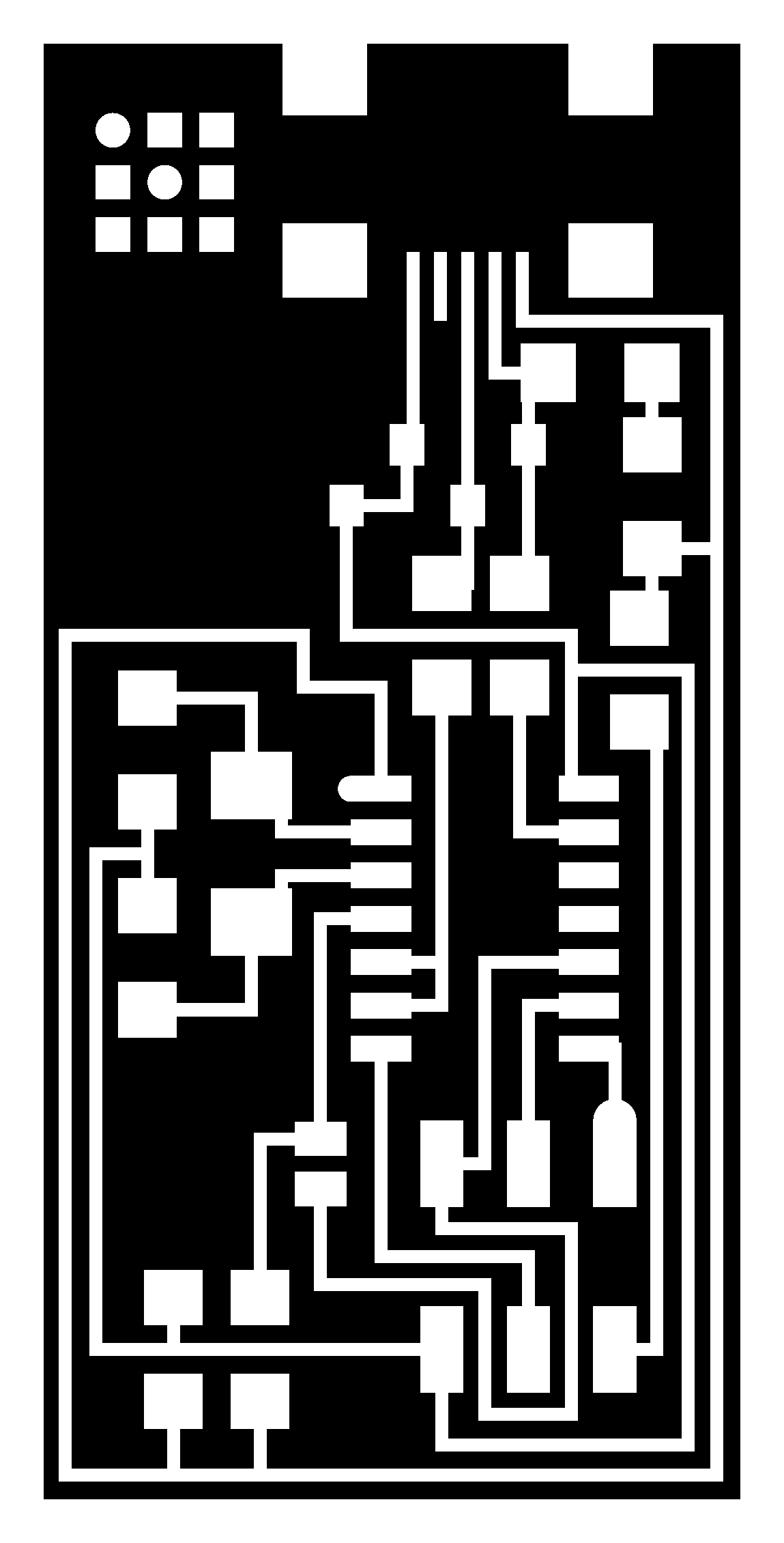
1. Download the board files 'png'. In my case, I chose Neil's FabISP.2. Open FabModules. In this page you can convert diferent formats into paths that the differents machines of Fablab can read.
In my case, I select the two documents 'png' (interior and traces) and I convert for the Rolland mill 'rml', and I choose also the tool (to make the traces is with 1/64, and to make the interior is 1/32).
Here you can choose:
Output:
The machine: SRM-20
x0, y0,z0: 0 (is the origin of the tool)
xhome, yhome, zhome: 0, 0, 5 (is where the tool will go went it finishes)
Process (all of them will be appear by deafult when you choose the tool):
Calculate button: You can watch the way of the tool it will do (like in the image)
Save button: To save the document for the machine
Number of offsets: You can change it, is the distance between the traces and the rest of the cooper

Preparing the machine
3. Clean the machine. Clean also the board and be sure that the sides of the board are flat.4. Put double-sided tape on the bottom of the board and place it on the tray.
Milling
5. Put the tool 1/64 in the machine.6. Open VPanel, the Roland software to manipulate the machine.
Move the tool of the machine with the 'x' and 'y' arrows, and place it on the origin and click the X/Y button on the right (to set the origin point).
To give the Z origin to the machine, you will open the machine and leave the tool touching the board. Now you can press the Z button on the right (to set the origin point).
7. Press the Cut button and select your file 'rml'. Go down the speed when it begins, and if everything it is ok, go up; if not stop the machine. In my case, at the beginning I put 40, and later 100.
To do the interior file, do not forget to change the tool, 1/32. To change it, you do not have to change the X/Y origin, change the tool and as before, to find the origin Z, leave the tool touch the board and fix it. Now press the Z button on the right (to set the origin point).
Welding
 You need:
Soldering iron
Toothpick
Wire of tin
Sponge (to clean the soldering iron)
AND A LOT OF PATTIENCE!!
8. To welding the components, first put some tin in one of the squares that will be the side of the component. Later put the component there and with the toothpick hold it and with the soldering iron welding it. Later weldint the other side of the component.
Components list
| Name | Serial number | Quantity | Reference |
| IC MCU AVR 4K FLASH 20MHZ 14SOIC | ATTINY44A-SSU-ND | 1 | IC1 |
| Bergstik Headers 2X3P UNSHRD HDR 30 | 649-95278-101A06LF | 1 | J1 |
| CRYSTAL 20.000000MHZ 8PF SMD | 644-1039-1-ND | 1 | 20 MHz |
| DIODE ZENER 3.3V 500MW SOD-123 | BZT52C3V3-FDICT-ND | 2 | D1 D2 |
| CAP CER 10PF 50V 5% NPO 1206 | 311-1150-1-ND | 2 | C2 C3 |
| CAP CER 1UF 50V 10% X7R 1206 | 445-1423-1-ND | 1 | C1 |
| RES 499 OHM 1/4W 1% 1206 SMD | 311-499FRCT-ND | 1 | R2 |
| RES 100 OHM 1/4W 1% 1206 SMD | 311-100FRCT-ND | 2 | R3 R4 |
| RES 1.00K OHM 1/4W 1% 1206 SMD | 311-1.00FRCT-ND | 1 | R1 |
| RES 10.0K OHM 1/4W 1% 1206 SMD | 311-10.0FRCT-ND | 1 | R5 |
| RES 0.0 OHM 1/4W 1206 SMD | 311-0.0ERCT-ND | 2 | SJ1 SJ2 |
| CONN RECEPT MINI USB2.0 5POS | H2961CT-ND | 1 | J2 USB |
Test the board
 9. With a tester, test the connectivity of the board.
You can also test the value of the resistors and if the Zener are in the correct position. For both of them remember to change the selection, fot he Zener you have to chose the tension [V] and for the resitors the resistence [OHM]. Be careful, there are different ranks.
Programming
I programmed with a computer of one collegue who has a Mac, because is more easy that in Windows. The steps are:1. Download and install Crosspack AVR.
2. Download the FabISP firmware.
3. Power up the board with ATAVRISP2 Programmer.
4. Open the terminal / command line interface and move to the firmware directory.
5. Compile the firmware:
5.1. make clean
5.2. make hex
6. Set the fuses so the board will use the external clock (crystal).
6.1. make fuse
7. Program the board to be an ISP.
7.1. make program
Programmer
To use the FabISP as a programmer I taken out the two bridges (resistors of 0 ohms).

DOWNLOAD FILE:
Interior (PNG) Interior (RML) Traces (PNG) Traces (RML)