


06. ELECTRONICS DESIGN
INTRODUCTION
The goal of this assignment is learn how to use a/some software(s) for circuit board design.
Students should have:
Shown your process using words/images/screenshots
Explained problems and how you fixed them, including how you worked with design rules for milling (DRC in EagleCad and KiCad)
Included original design files (Eagle, KiCad, Inkscape, .cad - whatever)
hello-world board
Software for circuit board design: Eagle
1. Download and install Eagle (you can download the free version in the autodesk web).2. Download the Fab.lbr and add it in the folder of lbr of Eagle.
3. Open Eagle and create a new project. In the menu: 'File' => 'New' => 'Project'.
4. Create a schematic for the new project. Click with the right button on the new project and select. 'New' => 'Schematic'.
Eagle: Schematic
With this new screen you have to put the different components and link them.5. To add the components, in the left menu there is a option that if you put your mouse on it, appears 'Add'. Click on it.


Components list
| Description | Fab.lbr name | Quantity | Reference |
| Microprocessor | ATTINY44-SSU | 1 | IC1 |
| FTDI 6 head | FTDI-SMD-HEADER | 1 | J2 |
| Ceramic capacitor 1uF | CAP-US1206FAB | 1 | C1 |
| Resistor 10K | RES-US1206FAB | 1 | R1 |
| Resonator 20MHz | RESONATOR | 1 | XTAL1 |
| AVRISP 2x03 SMD head | AVRISPSMD | 1 | J1 |
I also added
| Description | Fab.lbr name | Quantity | Reference |
| Resistor 10K | RES-US1206FAB | 1 | R3 |
| Resistor 100 | 311-100FRCT-ND | 1 | R2 |
| LED 1206 | LED1206FAB | 1 | LED |
| Switch button | 6MM_SWTICH6MM_SWITCH | 1 | S1 |
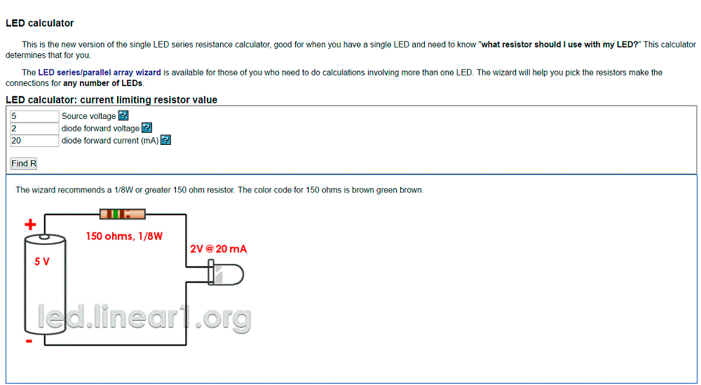
I use this web to calculate the resistence to not burn out the LED. Firstly, I selected a resistence of 499 but finally I changed to 100, in that way I am sure, also to not burn the LED and the LED will emit more light because the resistor is smaller.
7. When you have all the components on the window you can move and rotate them. For do that you have these two buttons on the left tool bar, you select one of them and go to the signal '+' in the component that you want to move or rotate. If you do not go to this point '+' you do not obtain the result that you want.
8. Label the different wires. With this button draw a wire in the different pins of the component that you want to connect. With every wire you have to click with the right button and select 'Name', put a name and later, one more time with the right button select 'Label'.
9. You can also change the name and the values (useful for resistors and capacitors) of the components, with the right button on the component.
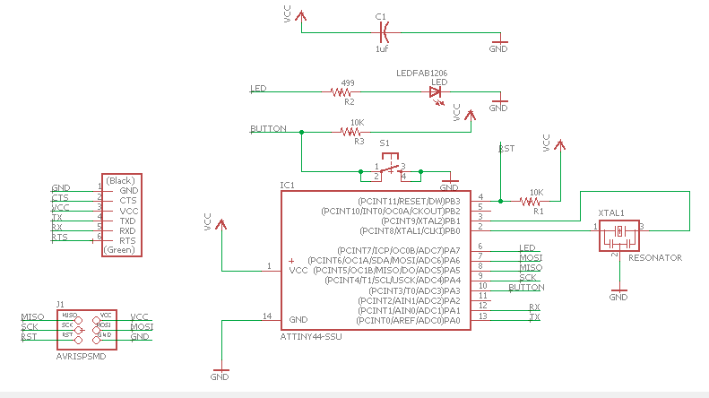
With this you will finish the schematic part.
Now to begin the board part, go to the menu and select 'File' => 'Switch to board'. This will open a new window.
Eagle: Board
10. In this window appears all the components with a yellow unrouted traces. You have routed them; to do that you will use these two buttons that are on the left tool bar. The first one is to routed, the second one is to unroted.
In my case, I had to change the grid, I select: Size => 0.05 mm. In this way, I can routed the traces in less size.
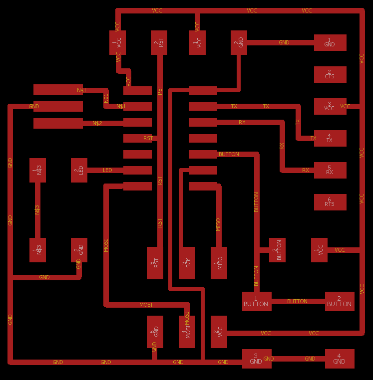
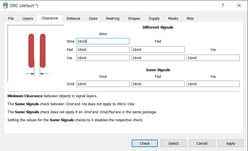
I had some problems because I did not use the 'Clearance' button on the left tool bar and when I finished the milling I could see that there was some routes that touch each other. This is useful to know that the wires, pads and vias have a mininum distance between them, I put 16 mil.
Export files to be milled
11. In the Eagle menu: 'File' => 'CAM Processor...' and save it as a 'eps'. You have to select only the: 'Top', 'Vias' and 'Pad'.12. With Photoshop I did the two 'png' files, one for the traces, and the other one for the interior. They have to be the same size.
13. The rest it is the same as the week 04: electroncis production.
13.2. Open FabModules. Generate the two 'rml' files (interior 1/32 and traces 1/64) for the Rolland mill.
13.3. Clean the machine. Clean also the board and be sure that the sides of the board are flat.
13.4. Put double-sided tape on the bottom of the board and place it on the tray.
13.5. Put the tool 1/64 in the machine.
13.6. Open VPanel, the Roland software to manipulate the machine.
13.7. Press the Cut button and select your file 'rml'. Go down the speed when it begins, and if everything it is ok, go up; if not stop the machine. In my case, at the beginning I put 40, and later 100.
Repet this process for the interior file(remember to change the tool).
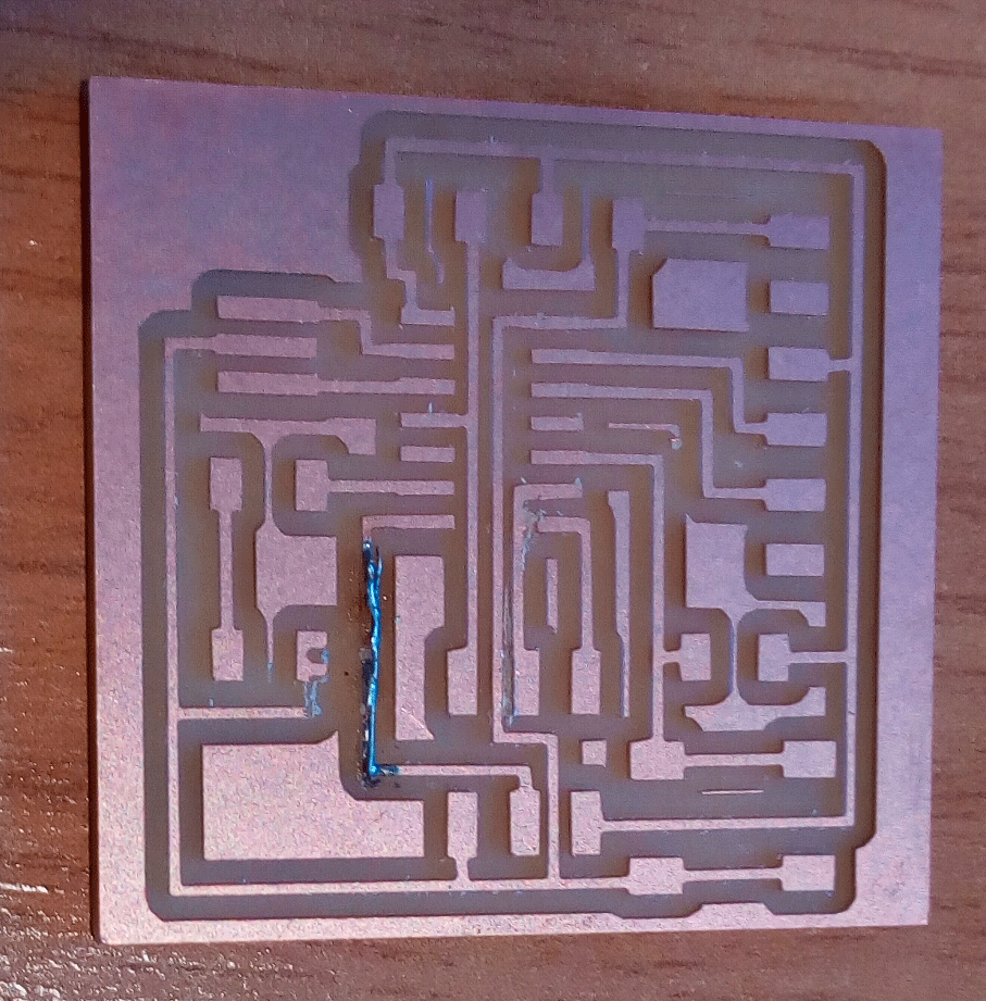
I had some problems. When I went to the FabModules web and I did the two 'rml' files which can be read for the milling machine; in this case, I choose uncorrectly the machine, I select 'MDX-20' (the correct is 'SRM-20). When I begin to milling the board I saw in the Control Panel that the cut depth it was only -0.04 and it has to be -0.1. I stopped and I did another time the 'rml' files and I did not change the board to not waste material. When I finished the traces, I view the board, and fortunatly, I could see that this mistake did not affects a lot to my board, but how I mentioned before I found more problems, there was some traces that touch each other. Finally I cut the board, with the interior 'rml' file (I change the tool, 1/32).
At the end I had my board, which returns from the war and I operate to solve the different problems. With a cutter I separate the traces that touch each other; and another traces which was cut (because I chose uncorrectly the machine), I weld a wire on it. To prove that the operation was successful, I used the tester.

DOWNLOAD FILE:
week 6 (RAR)