Week 15 : Networking and communication
This week's agenda for Fab academy was :
Designing and building a wireless or with wire network
connecting atleast 2 precessors
Led serial bus
For this week, It is very important to understand some terms that are used in making this assignment. This is a very vast topic and each, that is ,with wire and wireless communication requires the understanding of a lot of concepts. To begin with, This link is quite helpful in understanding these concepts.
In this assignment, I am learning to make a serial bus. In basic understanding, it is a series of processprs connected to a host board , a network sending messages to the board. When the boards receive this message, it blinks, when a particular board is called for, it respond by blinking twice. i.e in this particular case of my assignment. But broadly, this way we can speak to many boards via one message to call a particular board for action
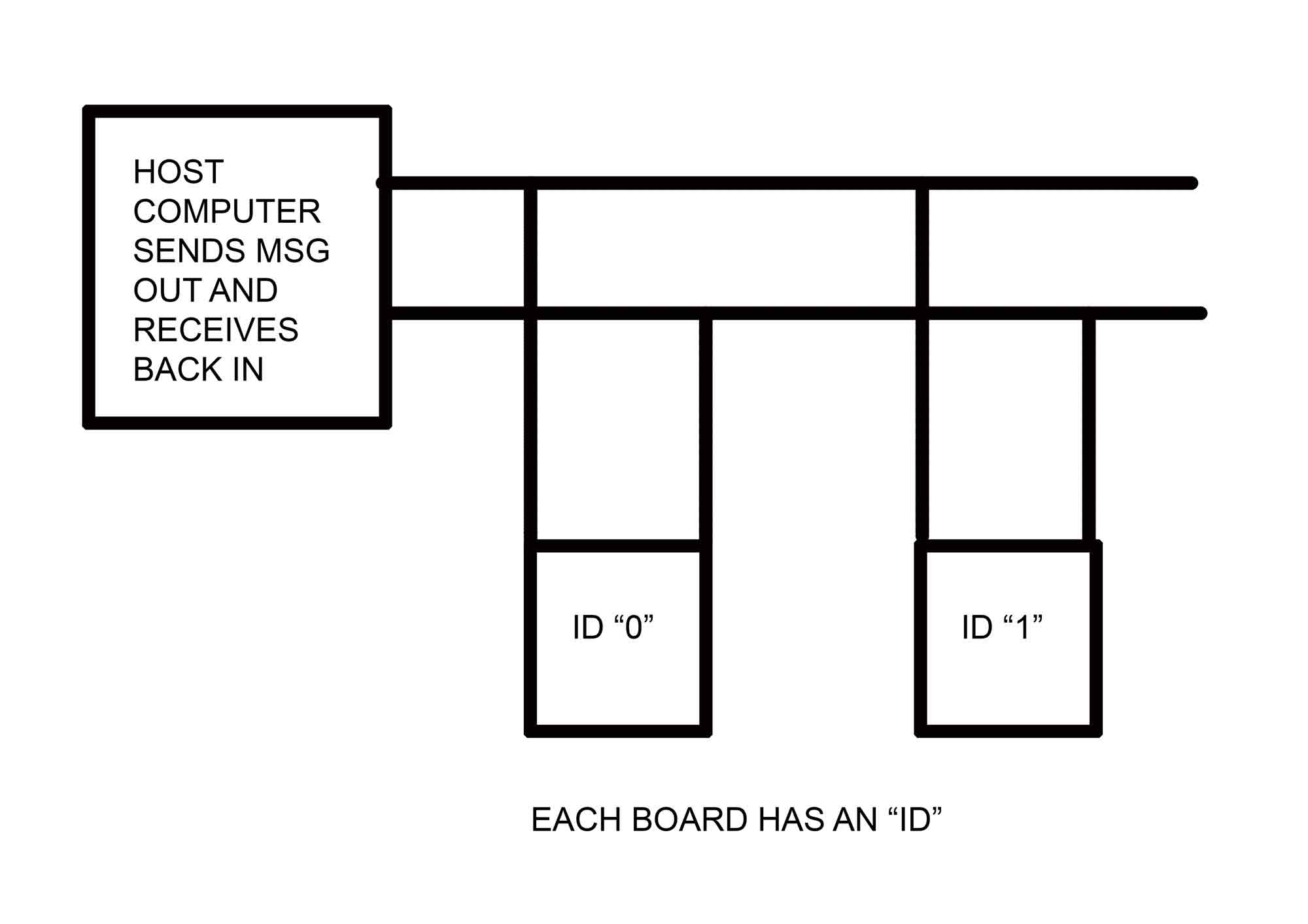
when the host sends a message to a particular board, all the boards get the signal and blinks once, the board that is called out, momentarily takes over the receive line and sends the message back and goes back to its state.The bridge board transmits and receives , and the node board has a positive and ground, and it also transmits and receives.
Each board gets a different id .
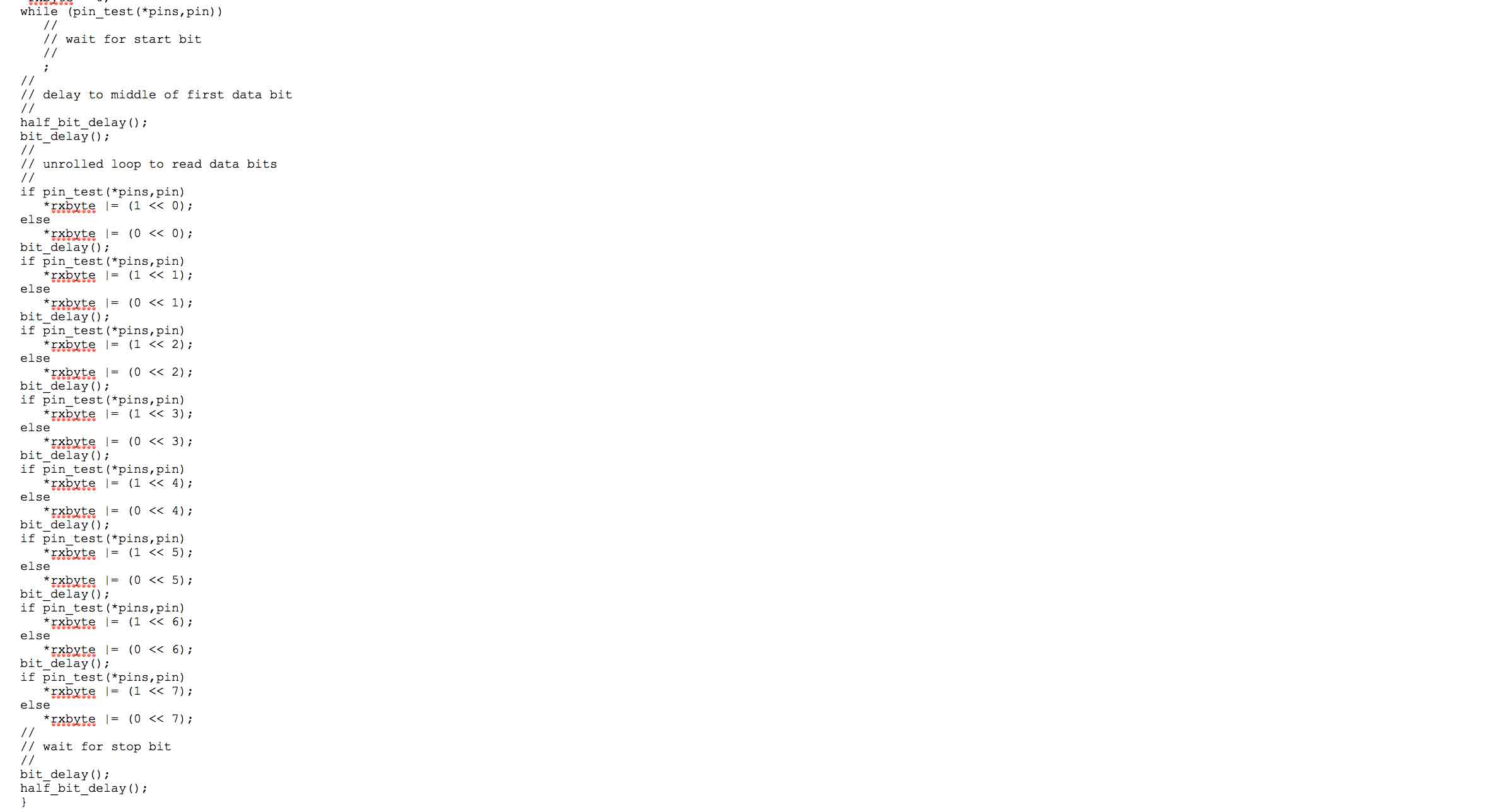
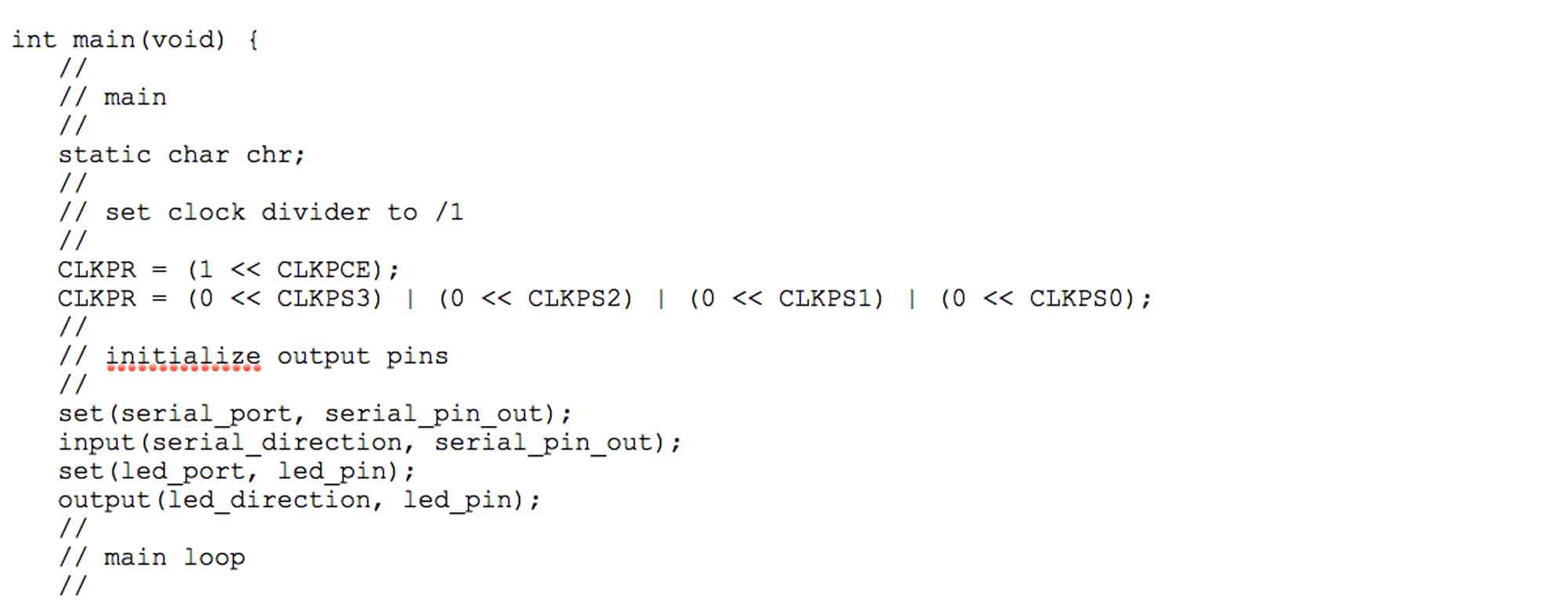
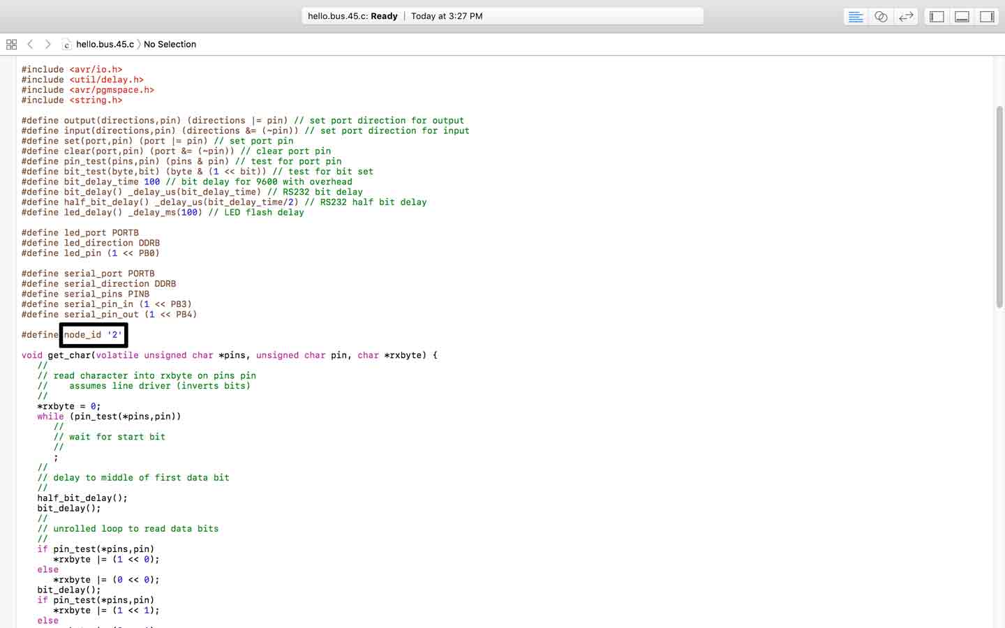
Now , lets look at what the code is doing in more detail.
Here in the code, we first notice the board id being defined. Then, the "get char ... " is where the board listens to the message. 'char' means charachter.
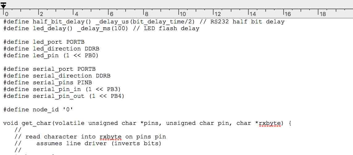
Then it checks if the charachter that is going out is the one that matches the id in the "if" statement.
Next peice of code , "output - serial dir, serial pin out ", It takes the serial pin and makes it an output.
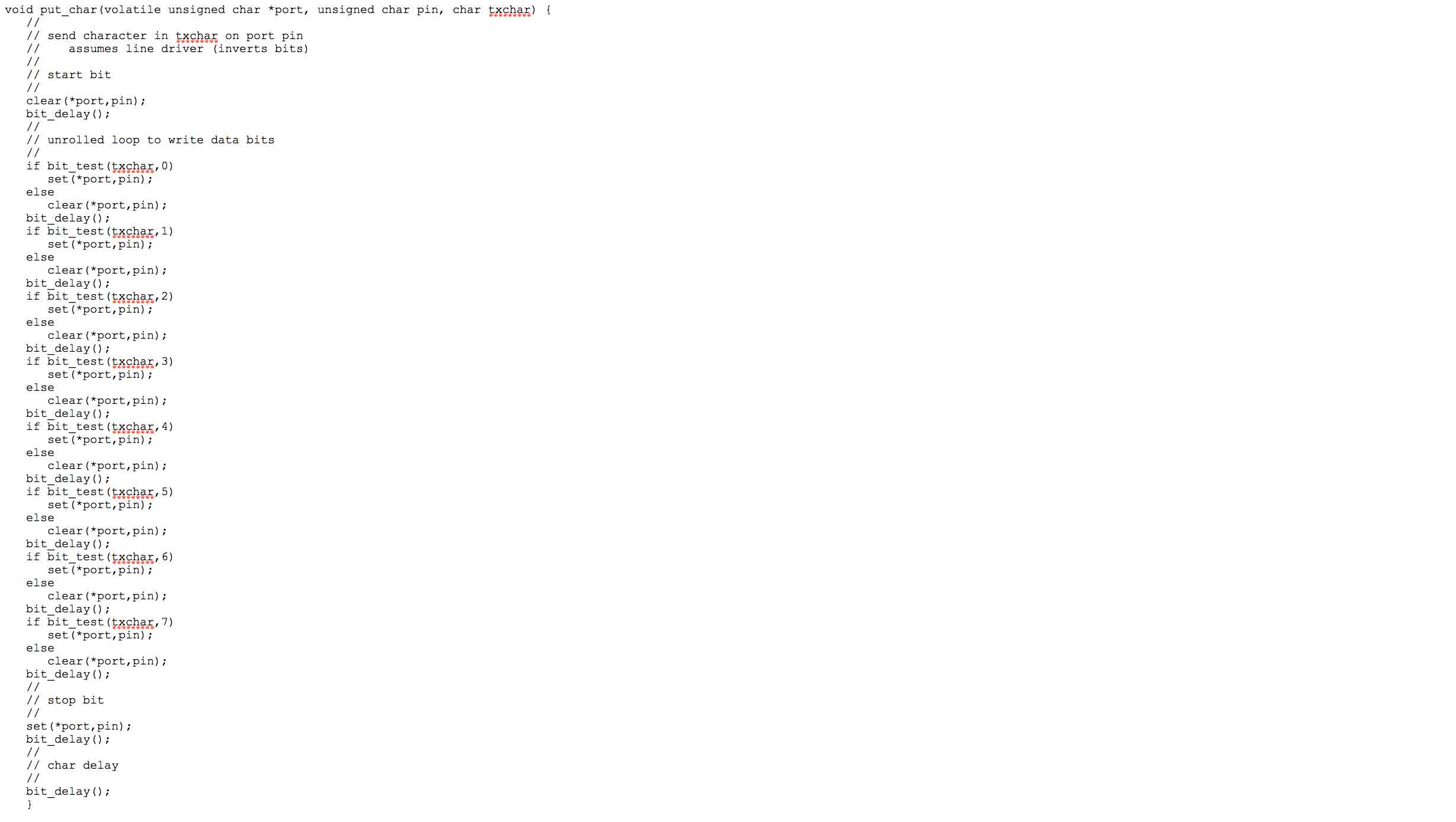
Next part of the code it sends out a message char message [ ] .
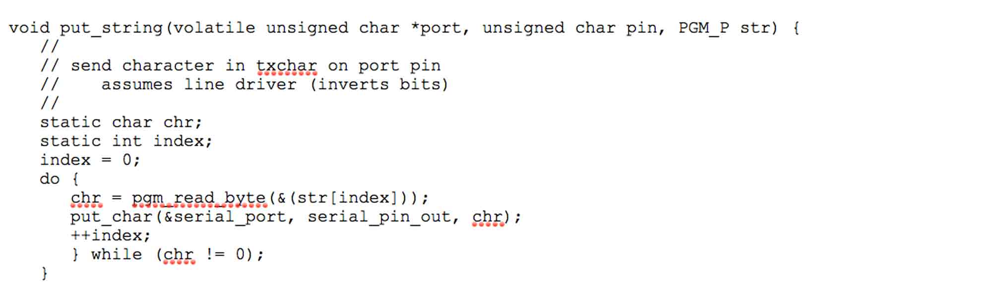
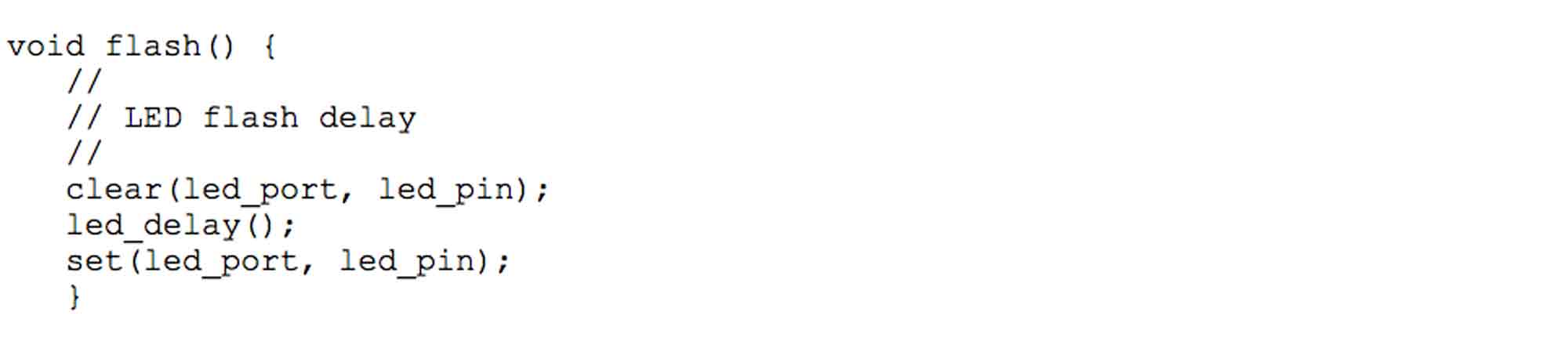
in this next part of code is when the called out id flashes for the second time
After the flash part of code, a crucial thing happens, It takes the serial pin and makes it an input again .
For my assignement, I will be making a serial bus with 1 bridge and 2 nodes.This serial bus will communicate with each other and light up the LED on the board based on the input parameter signalling from the bridge to the nodes.
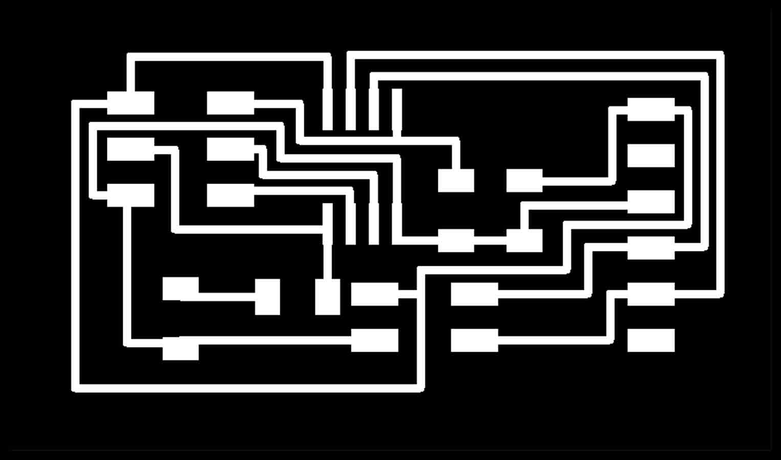
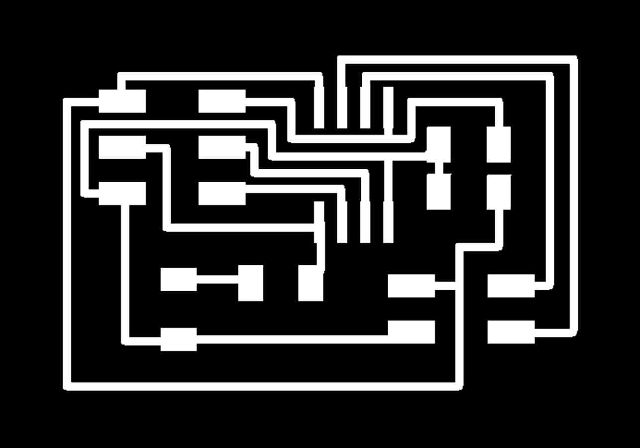
First I started with designing the boards on Eagle.I make my traces for the bridge and node boards.
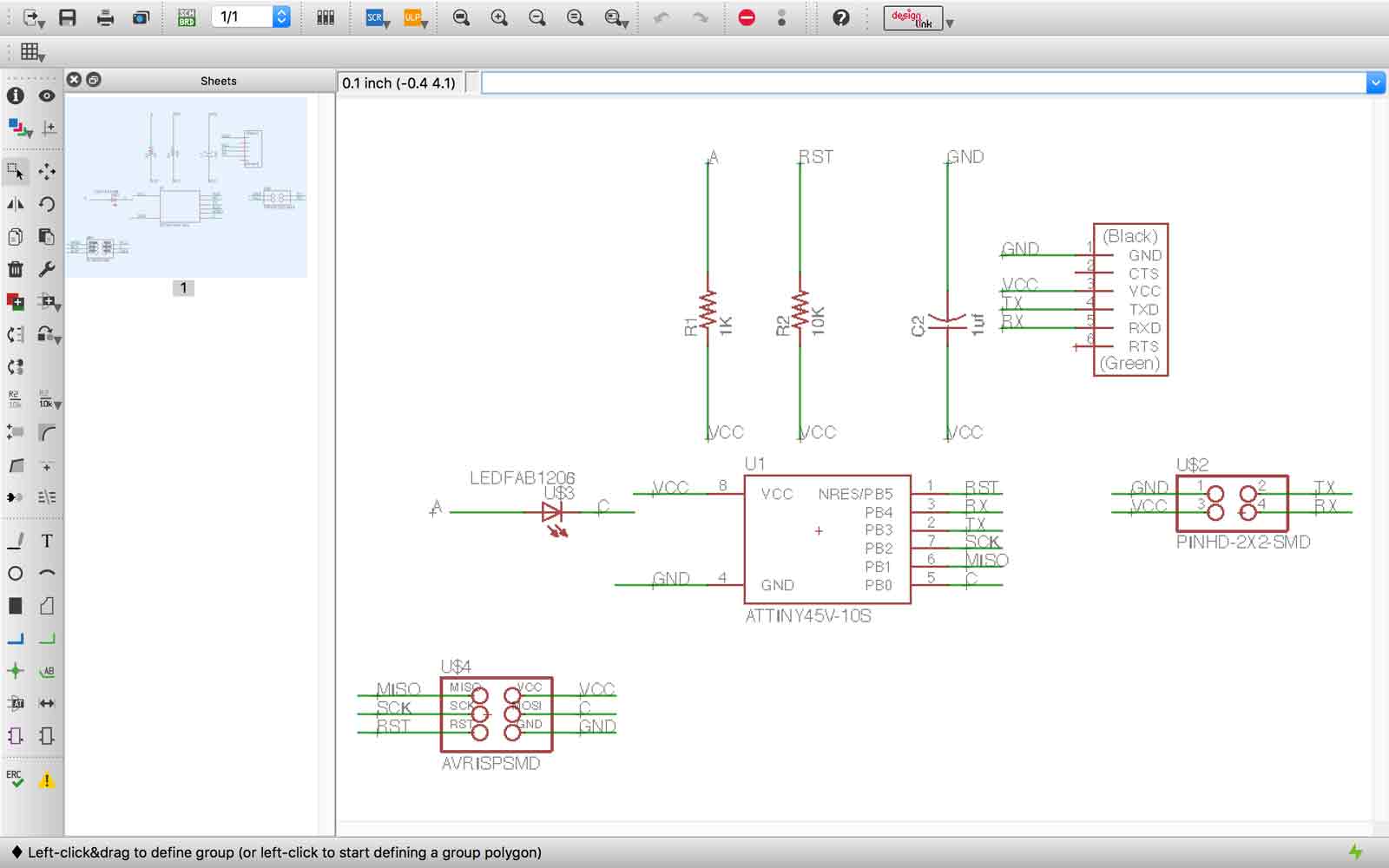
Once the files are ready on Eagle, I make the traces files that I can mill on monofab modela machince.
After , I Take it on to Fab Modules and make my files ready from milling the board.It is the same procedure as we did in other electronics machine that can be seen on my week 4 - electronics production and week 06 - Electronic design and week 10 - output devices. All the same setup steps are followed as before but with the new board design for a serial bus.
Once the milling was done, I soldered the modules,this is how my modules looked like.
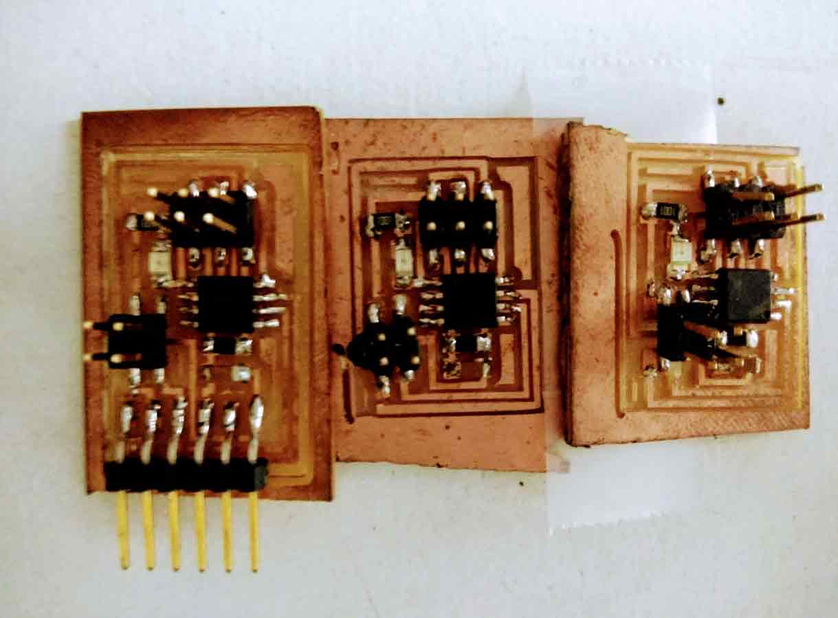
Now, before i forget, Let me mention the parts needed to solder, first, for the bridge:
For the node :
Once the boards are ready , we getting to the important part of the exercise, Programming the board.This is a fairly different procedure as apposed to the previous electronics exercise. Here it is important to make sure all the boards are connected properly without errors.
Before we proceed to checking the connections, let us understand a little more about the wiring and hardware of a serial bus. with more research from Sparkfun, I understood that, A serial bus consists of importantly of two wires - one for sending data and another for receiving. Serial devices should ideally have two serial pins: the receiver, RX, and the transmitter, TX.

It is important to note here, that, the RX from one device should go to the TX of the other, and vice-versa.Usually, in the projects, we are used to hooking up VCC to VCC, GND to GND, MOSI to MOSI, etc., but what is essentially happening in the serial bus is that the transmitter should be talking to the receiver, not to another transmitter.
A serial interface where both devices may send and receive data is either full-duplex or half-duplex. Full-duplex means both devices can send and receive simultaneously. Half-duplex communication means serial devices must take turns sending and receiving.
Some serial busses might get away with just a single connection between a sending and receiving device. For example, our Serial Enabled LCDs are all ears and don’t really have any data to relay back to the controlling device. This is what’s known as simplex serial communication. All you need is a single wire from the master device’s TX to the listener’s RX line.
Now , comin
Check if all the boards are connected properly to each other and the connections inside of the board.
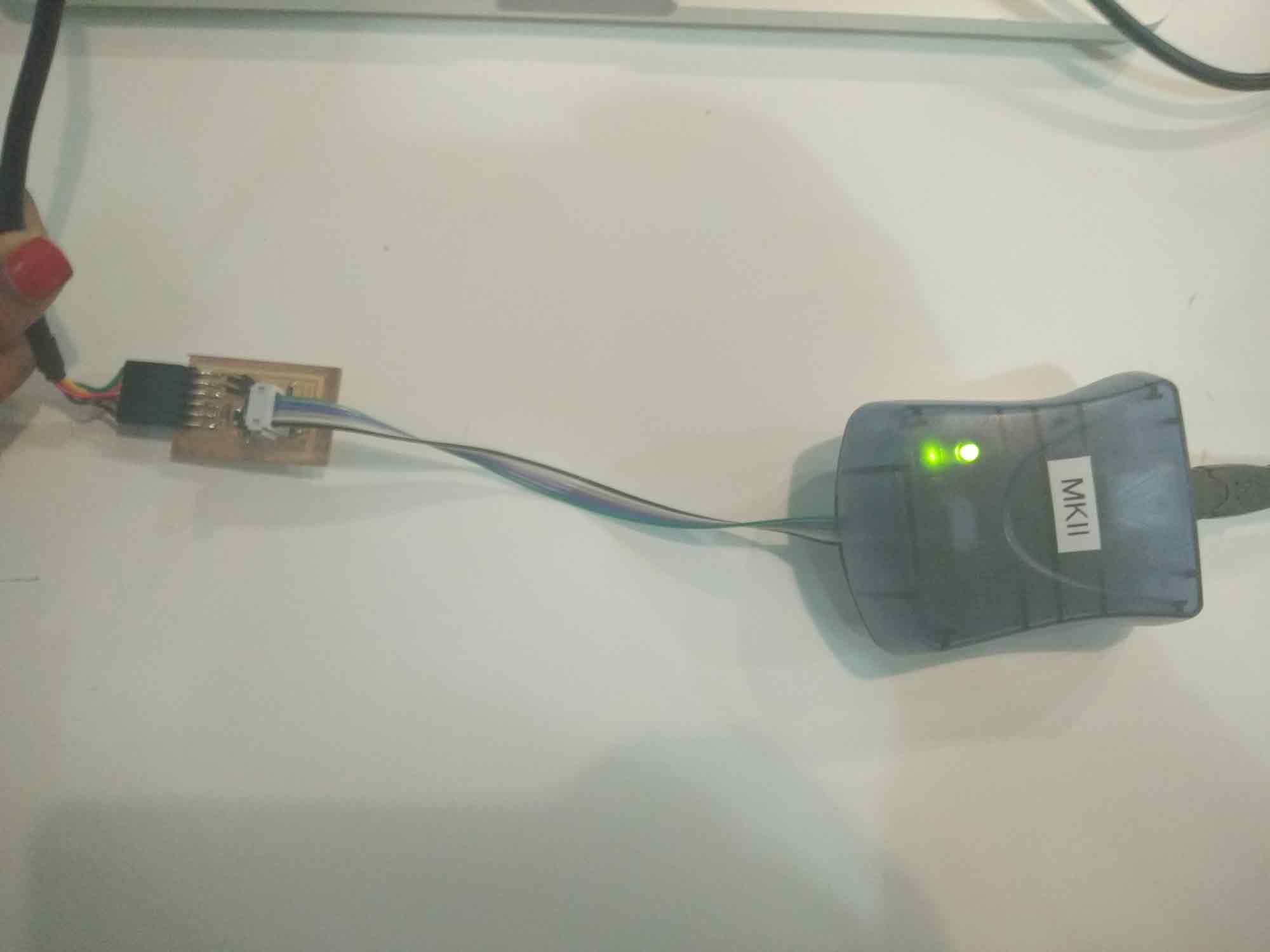
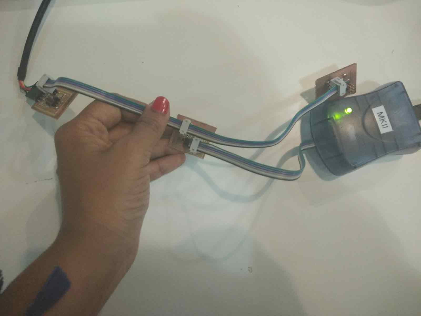
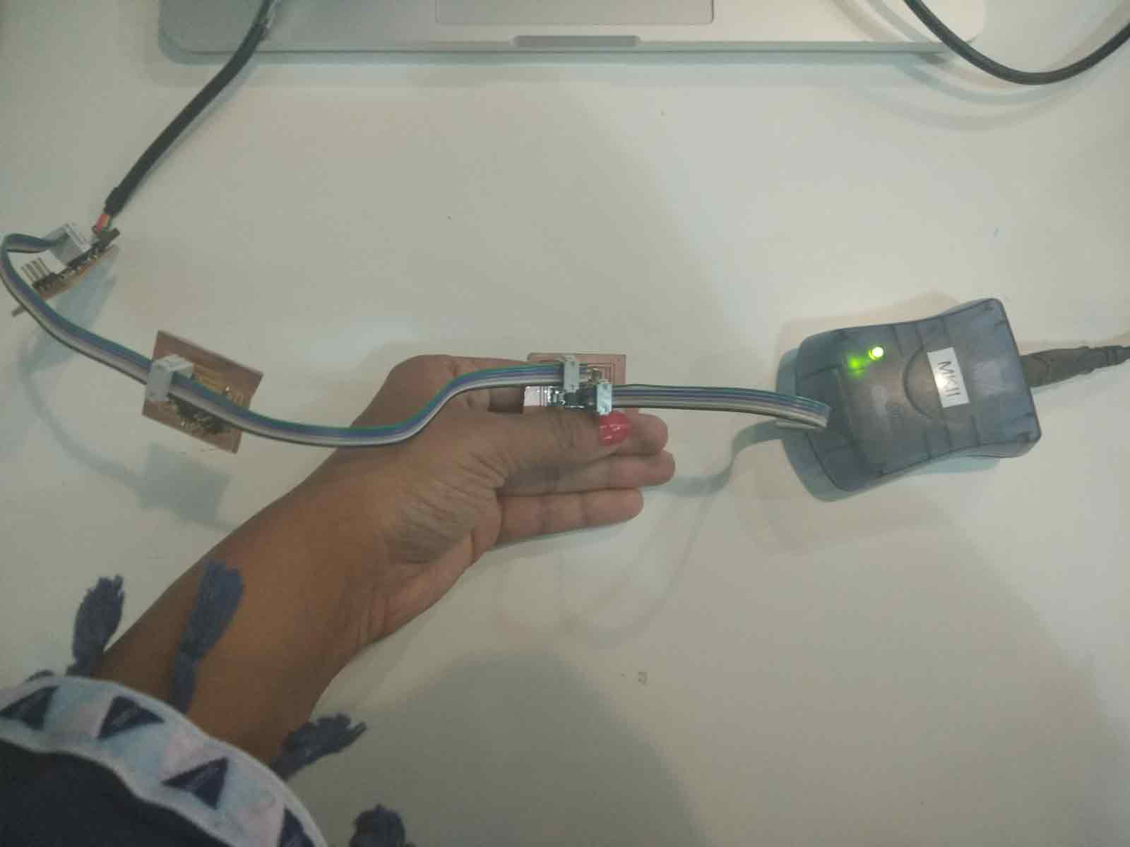
After i got the green light from all the boards , it was time to go ahead with my programming. Here I have used a .c code to program the board.
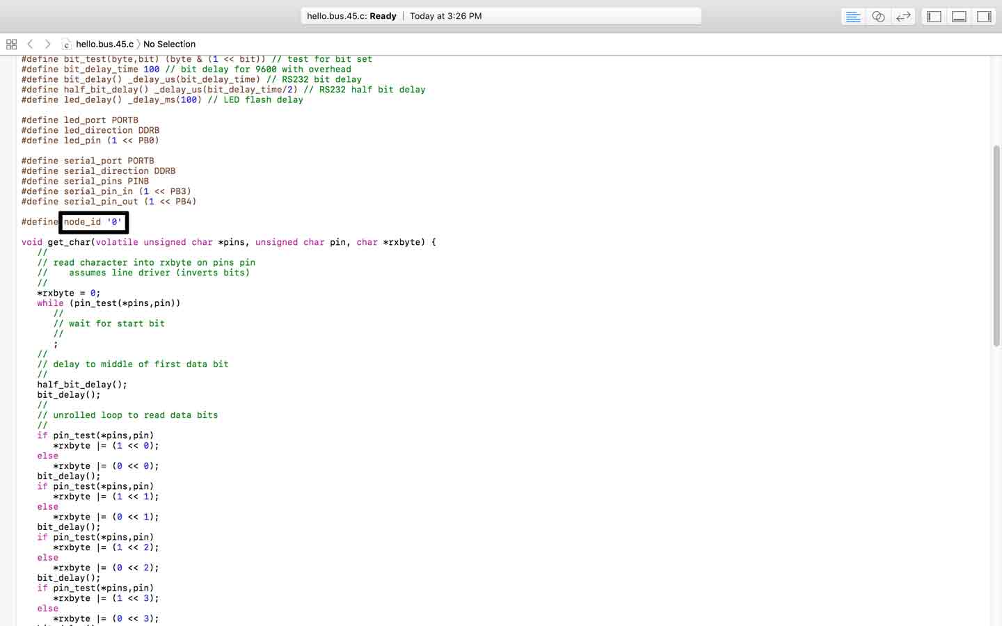
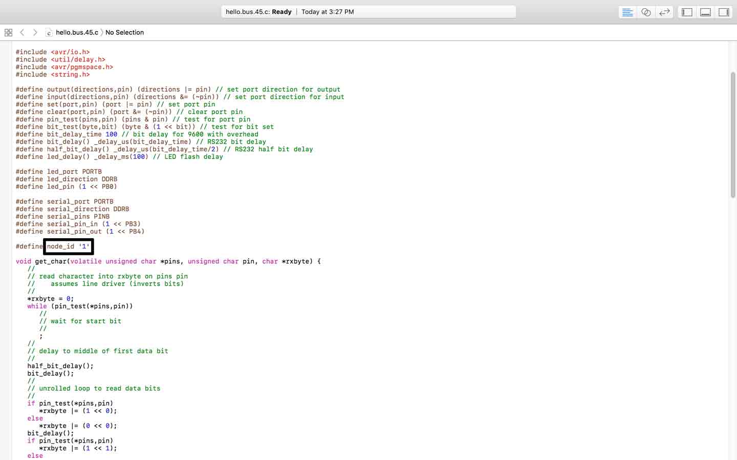
Here, When programming each board, we need to remember that each board has it's own node id.Node id for the bridge, has to be set to zero in the code, node id for 1 node board is set to 1 and the other is set to 2.
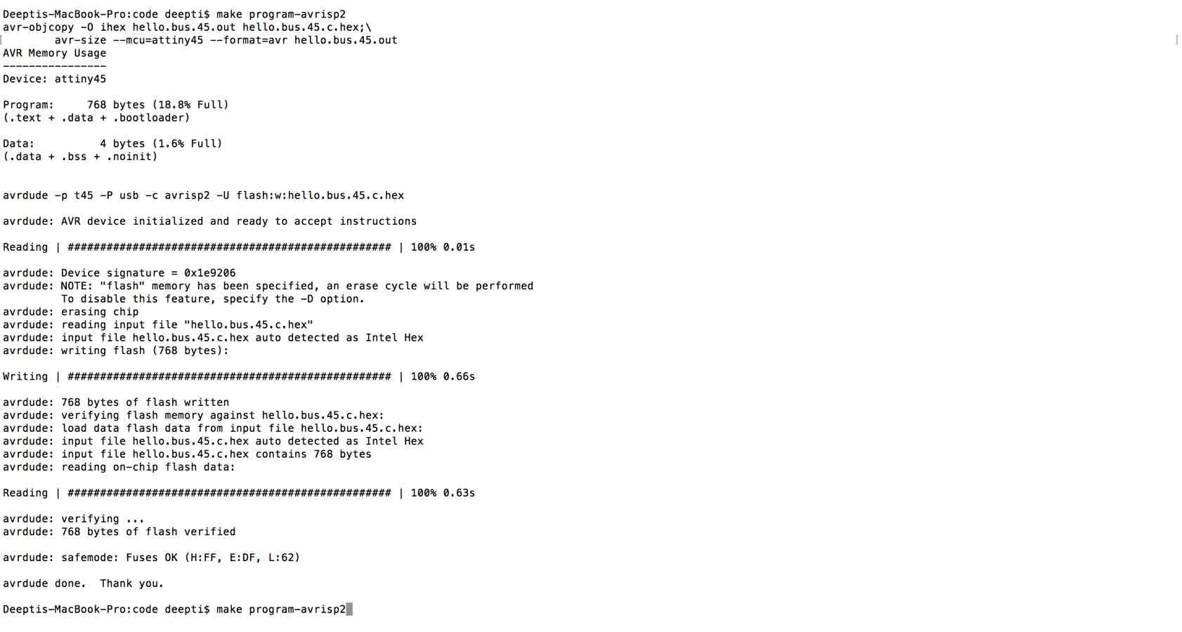
Once each board was programmed to the right nodes, It is now ready to be connected and programmed by the make file.the hello.c file.
This was a very complex topic for me, using the c code for the first time, and I would like to than Esteban Martín Gimenez who helped me understand and follow the code to make my project working.
Once everything was set up and code uploaded, it was time to test. You can see in the video how each board lights up according to the nodes it is set to, i.e., 0 , 1 and 2 respectively.Each board blinks it's LED first and then send the signal, the board /node that is called for is the last one still blinking.
And finally a success.
To view and download files click HERE
To download files click HERE