Week 10:Output Devices
This week's agenda for Fab academy was :
Add an output device to a board that was designed by me
Program the board to have the desired output
Output Devices
For my output devices, I tried the Satsha Kit by Daniele Ingrassia as I want to use an arduino board but this iteration to the arduino makes more pins usable!
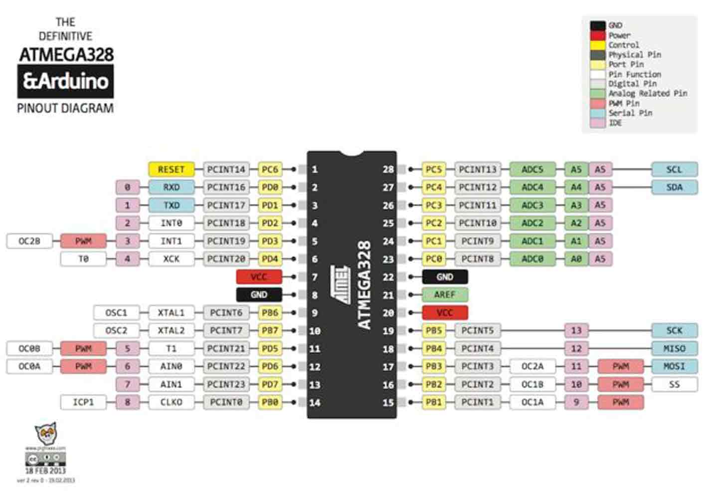
A Satsha kit uses the same microcontroller as Arduino, the ATmega 328p.From this data sheet, I understood how I could use the pin out and inputs to my advantage, thanks to the satsha kit modifications. As mentioned in the Satsha Kit web page it uses 16Mhz instead of 8Mhz, also a crystal instead of resonator, and it costs less (7-9 euro vs 13 euro), most importantly , it is 100% compatible with default Arduino IDE (satshakit is recognized as Arduino UNO) AND ADC6/7 connected instead of ADC6/7 not connected
This is for my final project.But for my project, I need a constant connection with the computer, as a MIDI controller constantly sends signals from an analogue input or buttons so to say to the computer which turns the signal to digital in order to give an out put of sound or graphics. This happens in real time, as every time a key/button or basically an electrical signal is passed to the board which sends signals to the software in order to generate an out put.
For this reason I added an extra FTDI pin connection to my board and MODIFIED my board. Also, in the Satshakit, in order to program the board, the pins needed, i.e., MOSI, MISO, SCK, RST, VCC and GND are distributed randomly along the board as they are also used as pins that can be connected as input/output pins. So, I decided to also have the pins needed to program to be grouped together, just like in our Fab ISP.So that, its easier to recognise and connect , inorder to program it.
To start off, First, I understood the parts of the satsha kit, and started designing my own board on Eagle software

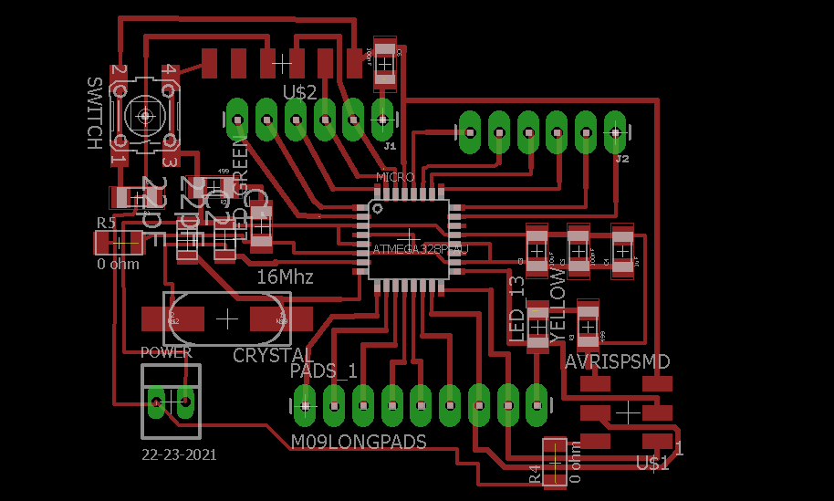
Once the board was designed, I exported the files from eagle to photoshop as an .eps file so that i could make the .png file to be loaded on fab modules.Here in this image, I am showing the traces file. But I made seperate files for the holes and the outline.
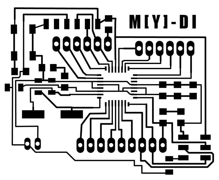
For the milling process of the traces, I set the offset on fab modules for my board as -1, I wanted clean traces with no extra materials but the lines of the board, as this was for my final project. And, I want to keep the board open so it can be seen as oppposed to being hidden.
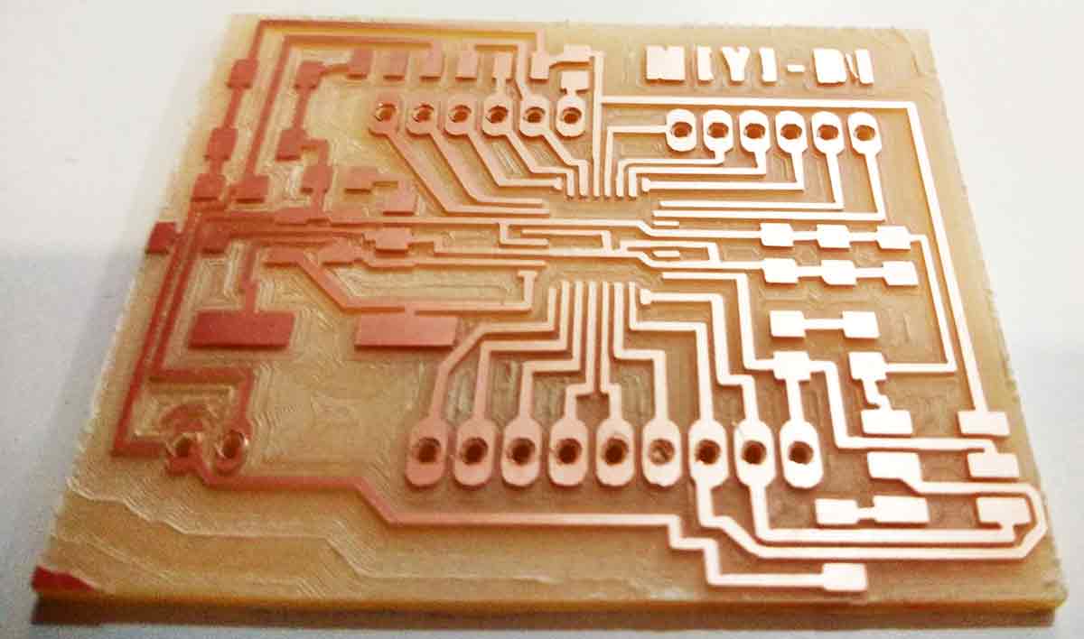
THis is how my board looked when I was done with milling the board on the roland Mill, I was quite happy with the end result. For the next part, was abput soldering all the components.The components needed were:
AtMega 328P
Crystal 16MHZ
Capacitor 22pf
Resistor 10k
Capacitor 100nf
Capacitor 1uf
Capacitor 10uf
Pin headers
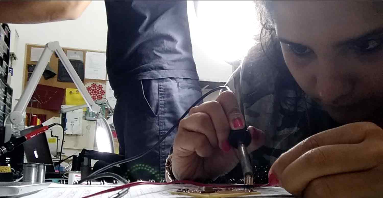
Once i soldered the components, this is how the board looked.

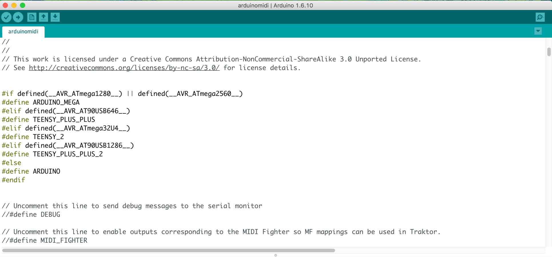
The next step, was to program the board. One important note to be made here is, When I tried to program it with a commercial programmer, like the AVR ISP , it kept giving me a "fuse lock" error.Then I tried to program it with the Fab Isp and followed the instructions on the link of the webpage mentioned at the beggining of this page, there was no fuse lock error when I programmed it with the Fab ISP.This took quite a while to figure out that the problem was not with my board but it was due to the commercial programmer that it was not getting programmed.Once I bootloaded it as an Arduino, I uploaded the blink sketch to see if i works, and it did!

Having said that, This blink example was only to test the working of the satsha kit I made, The details about the MIDI controller and the process that was accomodated in my final project can also be checked in this week 13 page.
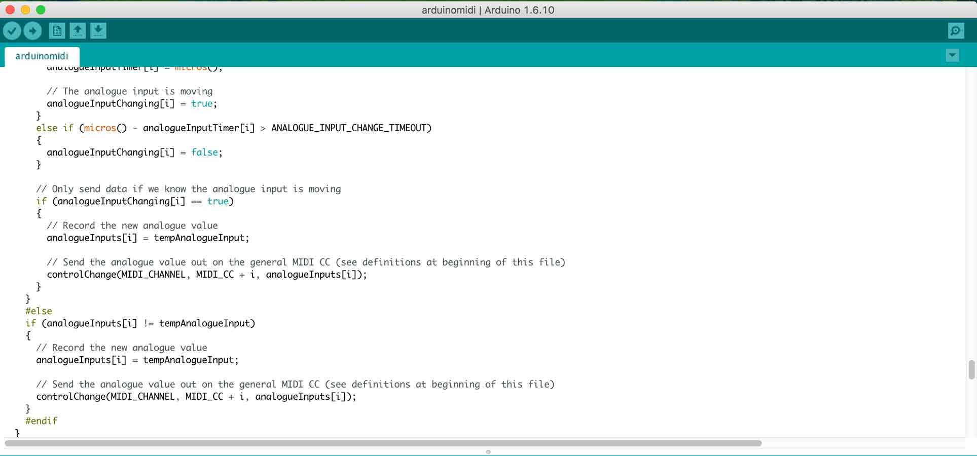
What essential happens in a MIDI controller , well a MIDI is a Musical Instrument Digital Interface, so this Micro controller helps interface and communicate with a digital music tool or electronic intrument with analogue inputs.Lets understand what is happening in the code, breifly. In here, The first step, we define arduino, as the board/controller we are using as the MIDI controller board.
Then, we define the parts of the MIDI device which helps to make the music, that is, the MIDI notes, the reverb, chorous, controls, etc.,

The next part of the code defines the MIDI channel and notes in accordance to the pins.
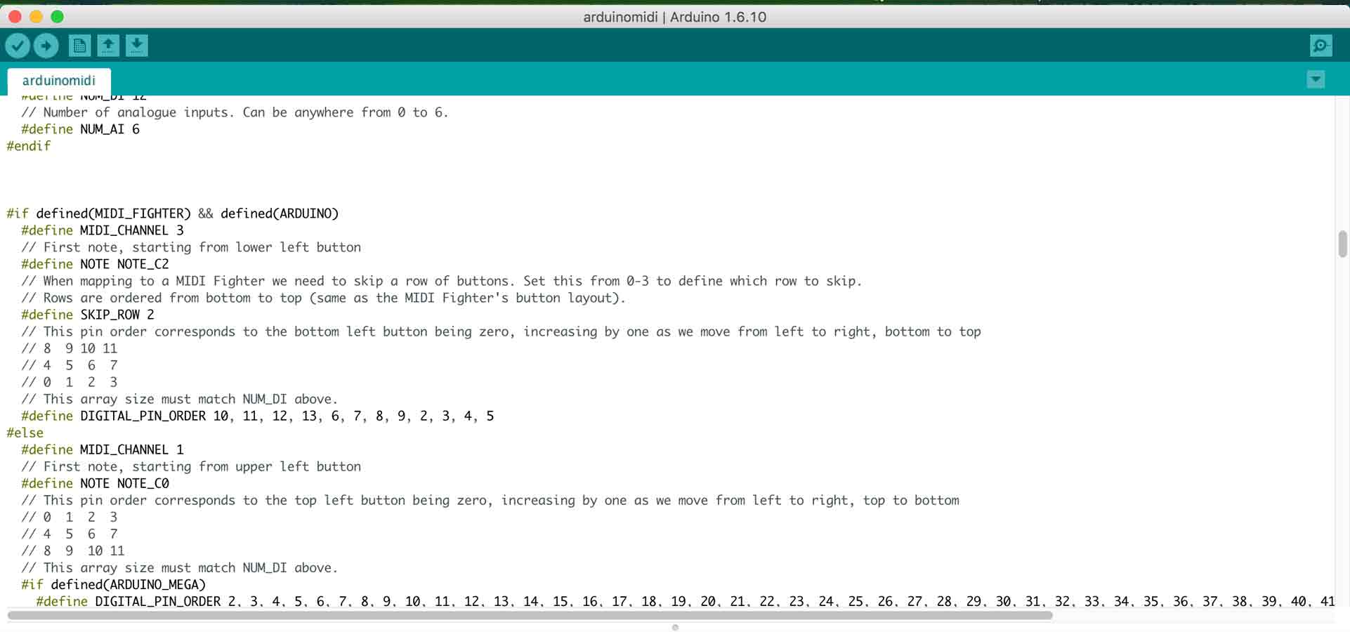
Then, we map the pins of the analogue input of the MIDI device which helps to make the music, to the MIDI notes.

In the void set up, we beigin the serial, we call the pinMode and we intialise digital with a read to the input pin.

we then call the if and else functions for the MIDI note to turn on and off.
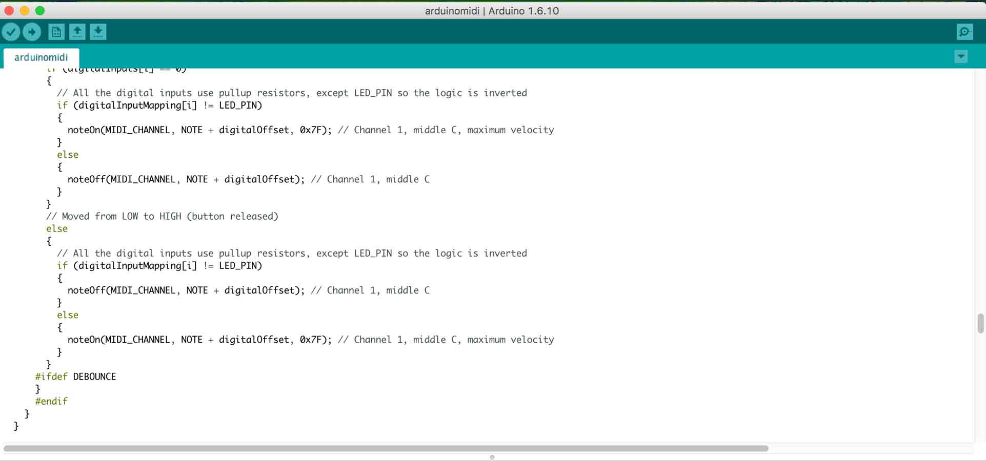
And finally define the functions of the Analogue input.
Once my board was ready and programmed , I uploaded the MIDI code from the arduino IDE on to my customised Satsha kit . In order to test it, I soldered one pin and connected it to the tactile button on the breadboard and the arduino was connected as a MIDI and was giving me the desired output and the board was successfully connected as a MIDI board.
To view and download files click HERE
To download files click HERE