Electronic Production
Electronics production is a relatively new topic for me. Although, I have used some basic Arduino board for simple coding before, to understand the function and working and making of a PCB was a very interesting exercise.
For this week, we made an in system programmer for AVR microcontrollers and we used the FabISP module/template.The ISP is very useful because this can be used to speak/communicate to other AVR controllers usig a 6 pin IDC to a 6 pin IDC and code it in order to perform a set of desired functions.
For the purpose of this assignment, and to start off our electronics journey, we had the help of Fab ISP files which we could use and edit in order to mill. This was a perfect starting point as we still had to lear to start designing boards from scratch which would happen eventually in the coming weeks ofcourse.
So, the first thing is to download the Files.
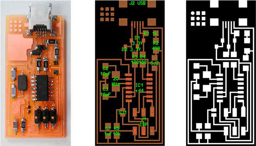
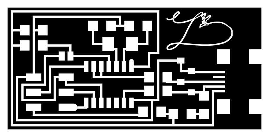
Once you have the template, we customise to make it our own. Here, I added a logo I designed for myself in order to distinguish my ISP from the rest.Rember to save the file as a 500DPI once you make the changes.
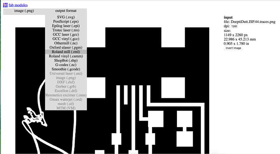
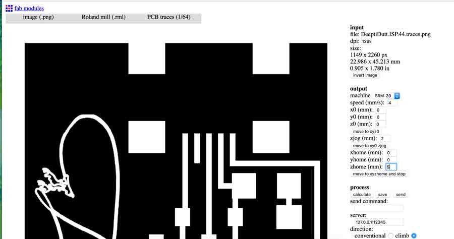
Once I had my template ready, We go to Fabmodules and select Input image png.Once that is done, select the output as the roland mill.rml as your output.It should look something like this image below.
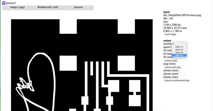
Once you have your output selected, selet the machine, in this case, at FabLab Barcelona, we select, SRM 20.The Process option for traces, you select PCB traces (1/64) for tracing your circuit.
Check your settingings once that is done. The important thing to remeber here is set the Zjog as 2 and Zhome as 5.The Zhome should be set at atleast 4 or 5, because once it processes the job and goes to home xyz point you had set, it should move up in z axis before, otherwise it scartches your board while moving back to z and you definately do not want this.
Once you have your settings right, click on calculate and you should see the traces of your board, basically showing the route it takes while milling the board.The image below shows how the traces look once we calculate.
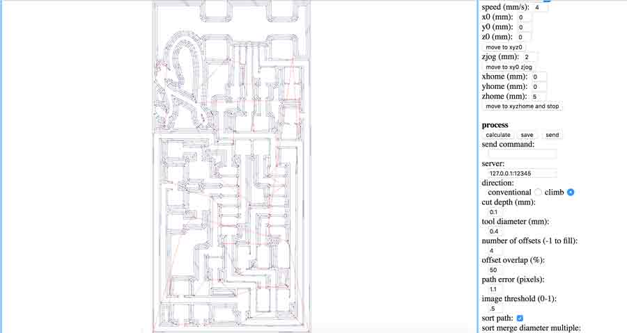
Once you have this, click on save, and save the file as .rml, which is how it saves anyway, as default. This is the file you input to the roland machine interface on the computer.
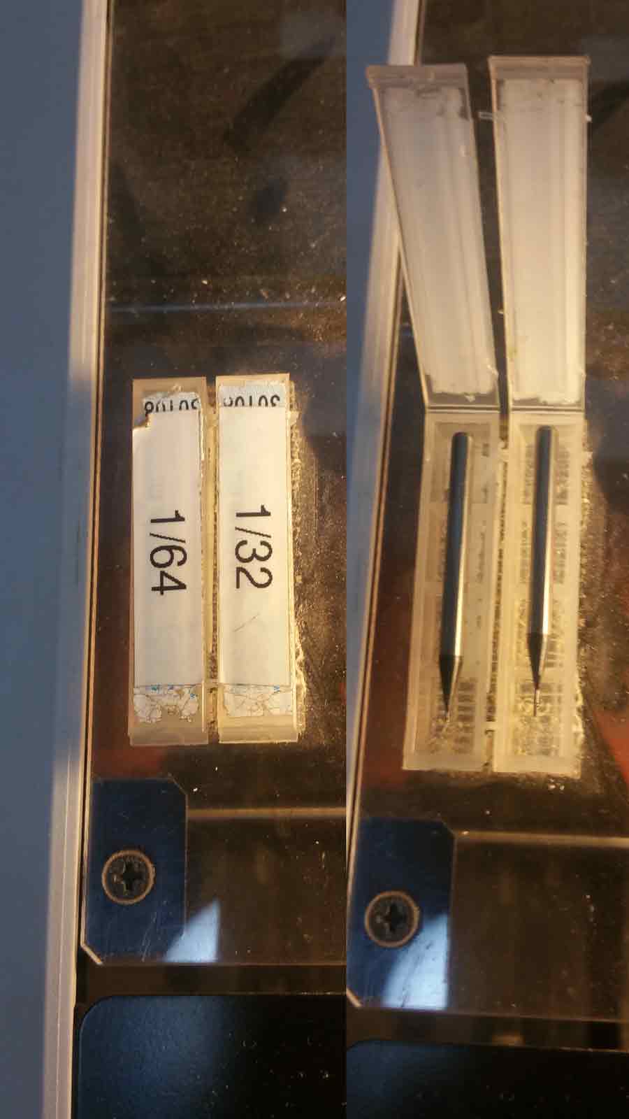
Repeat the same process for the OUTLINE. The only difference is , for Process you select PCB outline (1/32). The logic here is mostly, the change in the mill bit of the machine. we use a thinner dia millbit for tracing the circuit, in this case, 1/64, and for outline, since it cuts out your board from the outline image, we use a bigger dia mill bit, in this case, 1/32.
Once you open the roland mill software on the computer, Stick the copper board strongly on the tray so that the board does not move in the process of milling.
set your x and y home by moving the arrows, this is a fairly simple process. Now, while setting your z, be very carefull.Take the z down by pressing the down arrow button, close to the board but not touching the board yet. There are different scales of movement.Like - Continue - this moves the bit in a continuous motion, this is when you have to move from one end to the other, mostly useful for setting x and y. and when you need more precision, use the - x100, for more precision, -x10 or -x1 . this moves the bit either 100 steps per click, or 10 steps or 1 step accordingly. As you get closer to setting the z towards the board its better to use x10 or x1. Set the z carefully and precisely, and you are good to go.Click on the "cut" button select your file and click output.
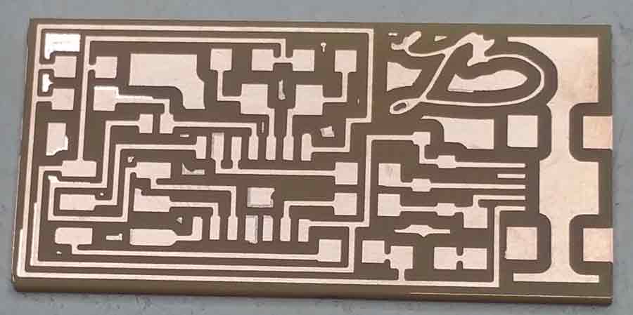
Finally once its milled, take out the board carefully from the board
Once you have the board, organise the components you need to solder in one place so its easier while soldering. The components are super small, for me it was super tricky as a first timer to hold it in place and solder. practice on a old board maybe, once we get into the grove of soldering, them it does not seem like moving the mout everest anymore!
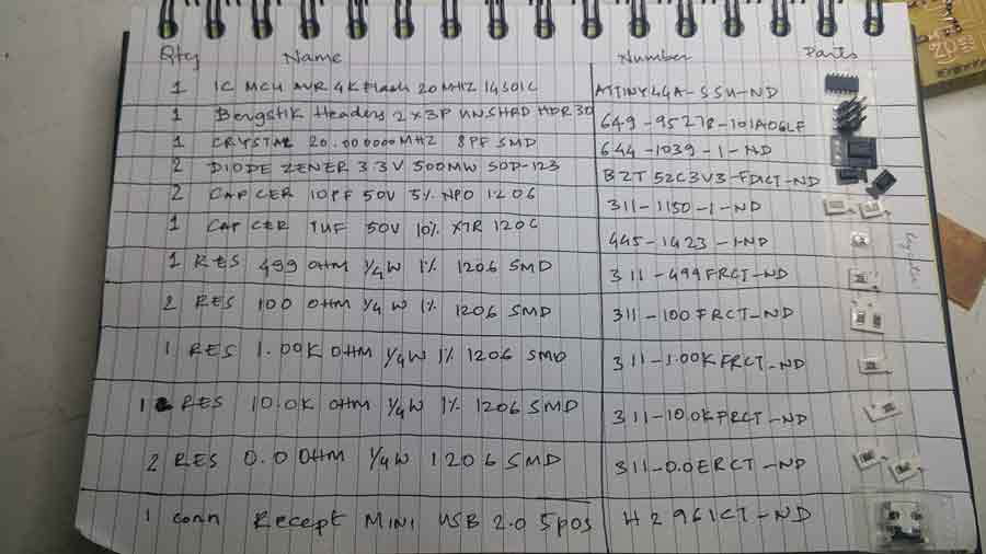
Set the board in place, so its comfortable to solder.
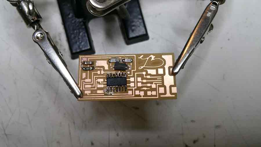
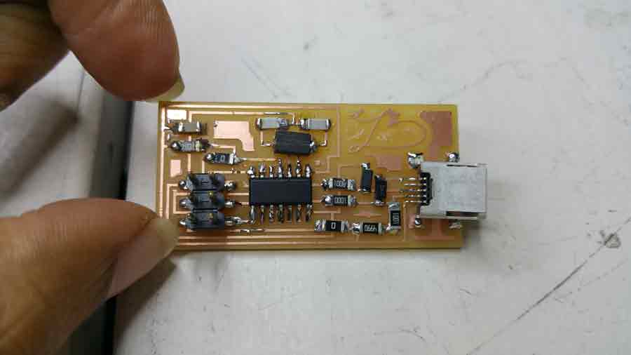
Once I was done with soldering, My board looked like this.
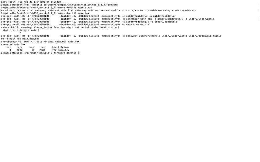
Now, for the programming! FabISP programming tutorial is very helpful . Once you get around it following the steps in the terminal, There are four important commands you type -
Make clean
Make hex
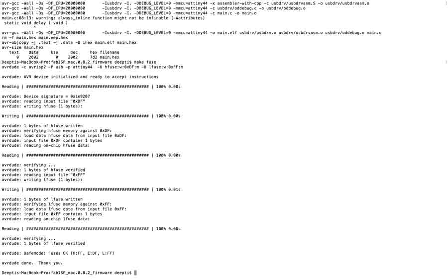
make fuse
make program
I used a mac book and here are the photos of my successful first attempt in programming my board.
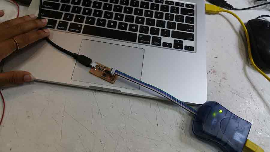
Yay! green light means the components are soldered correctly and the board is getting power. first step to success!
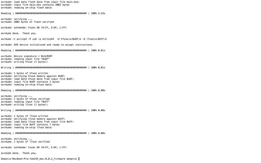
My board was programmed with no errors, and was recognised as Fab ISP.Once that is done, I unsoldered the two 0 OHM jumpers so that the board is recognised as a USB and cant be programmed again. Here is the final picture.
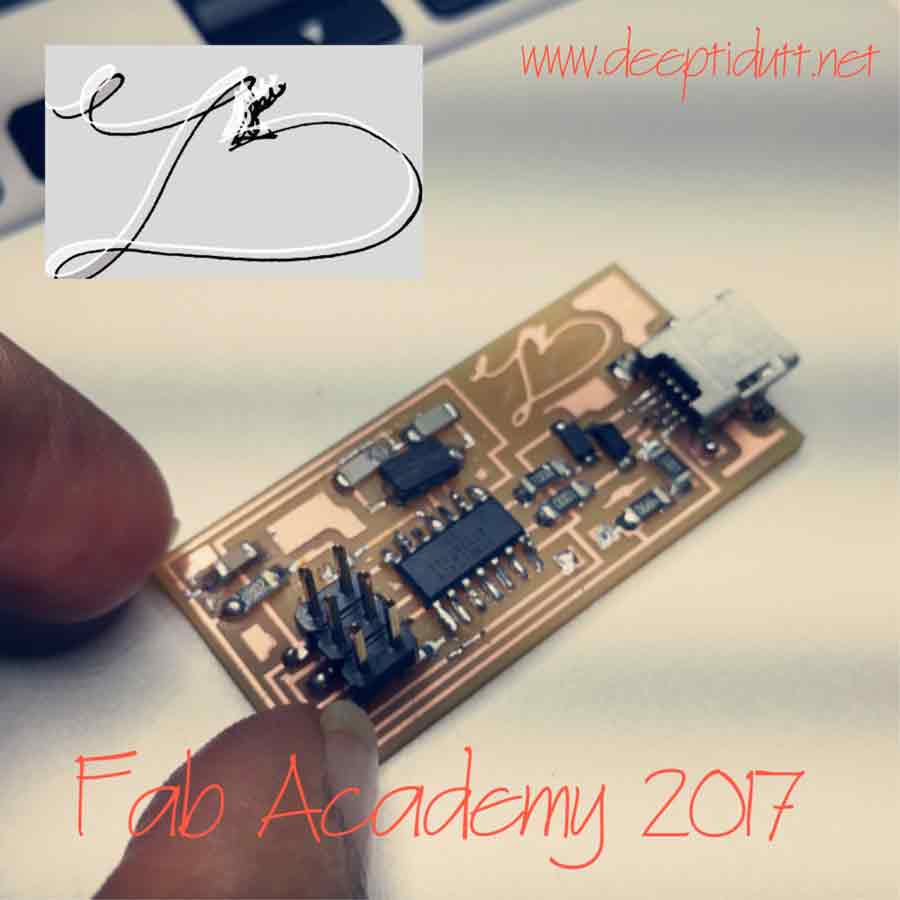
There was a certain genuine happiness in making this board and successfully programming it, a first time experience with the bottom up way to electronics.Fun!
Update : I also used my FAB ISP when I made my satsha kit during my out put assignment, to program it. Here is a video showing the Fab Isp being recognised and used to make the satsha kit blink an LED.
To view and download files click HERE
To download files click HERE