07 - computer-controlled milling
This week’s objective was to design and mill something big on the cnc mill.
I designed an object in Fusion 360 and used a Shopbot to mill it.
My goal was to make a modular set of shelves that can be used when assembling or soldering objects that have a lot of small parts. The idea is that you take all the parts you need for your job out of storage and put just the parts you need in these shelves to keep them in place while you work. This can be SMD components, LEGO bricks, jewelry, basically anything that has small parts.
Steps:
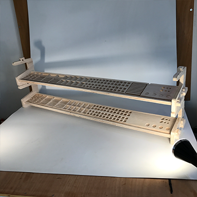
01 - make a design in Fusion 360
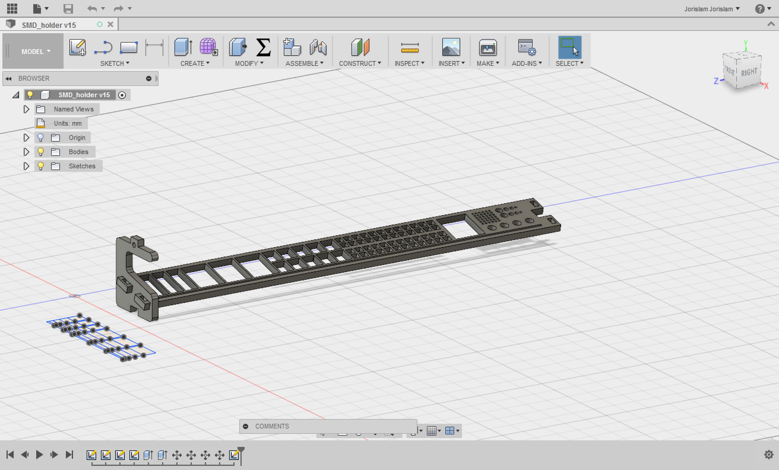
I just created two sketches and only used the 3D model to see if the connections would fit. All the depth of the pockets I added later in Partworks.
One BIG mistake I made in designing is that I forgot to give holes that need to fit another piece the circles at the corners. This came back to bite me in the ass big time later.
I exported the sketches as DXF files.
You can download the files at the bottom of this page.
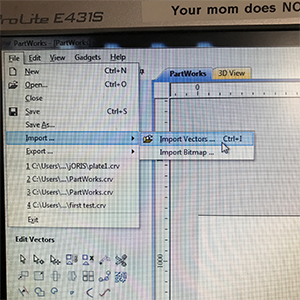
02 - preparing in Partworks
Partworks is the software I used to generate the paths and g-code for the Shopbot, it allows you to set the depths, dimensions and settings for your file and machine.
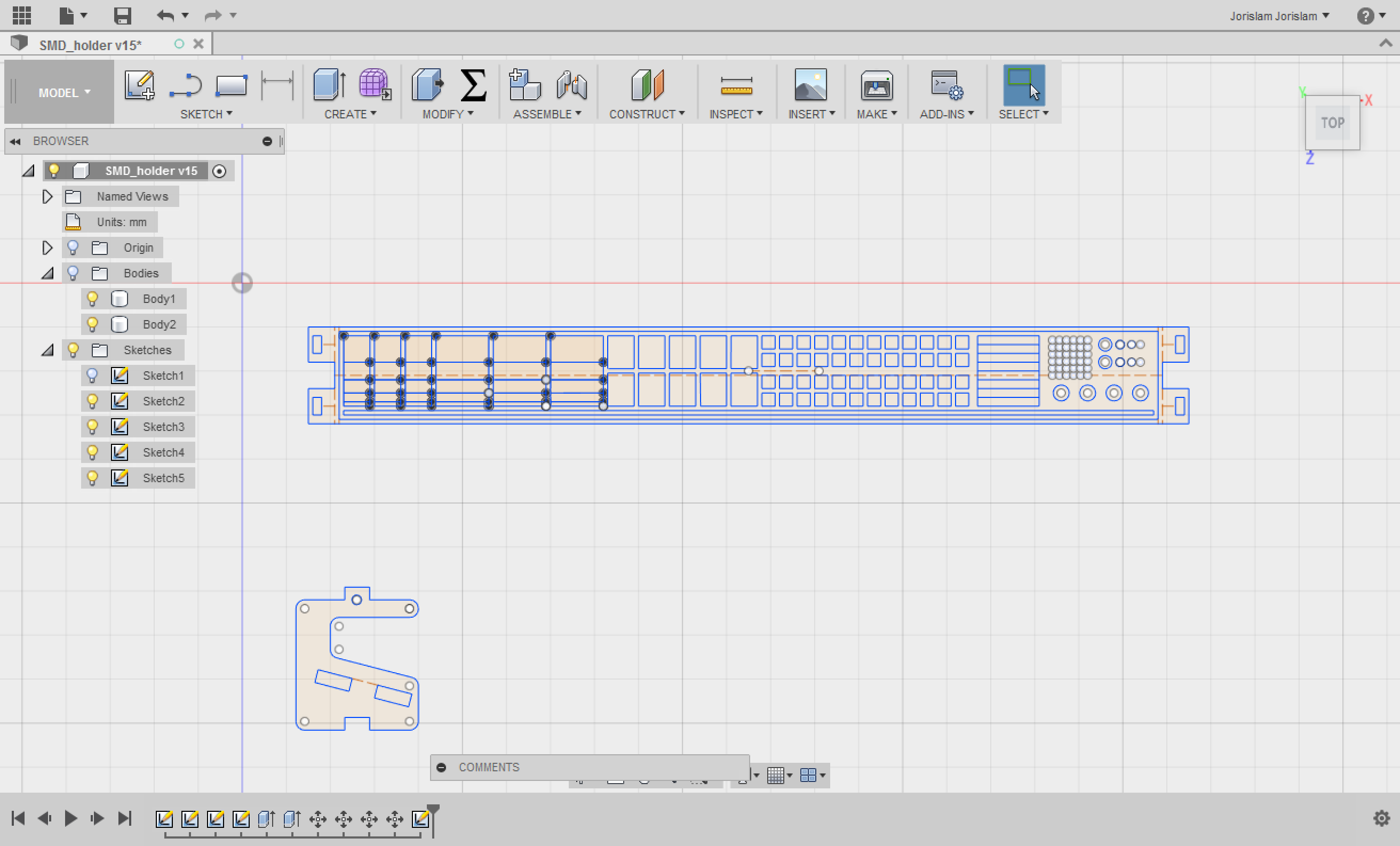
(sidenote, the computer connected to the Shopbot didn’t allow for screenshots, so I had to take pictures of the screen.)
First step, open a new file and set the dimensions for your material.
After this you’re ready to load your vectors into area that is the size of your material.
DXFs from Fusion 360 will also include construction lines that you don’t want in your job, so remove these lines first.
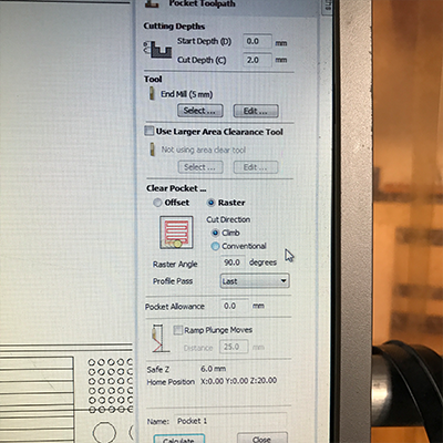
Once the design is cleaned up and in the right position, I started by adding pockets. I did this before setting a profile cutpath, but you can change the order later on too.
My design has A LOT of pockets, so I’m not going to show you every setting for each pocket, but rather the most used settings for the majority of the pockets.
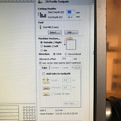
After all the pockets I did the same for the profile toolpaths, meaning the parts that need to be cut out completely.
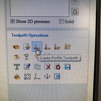
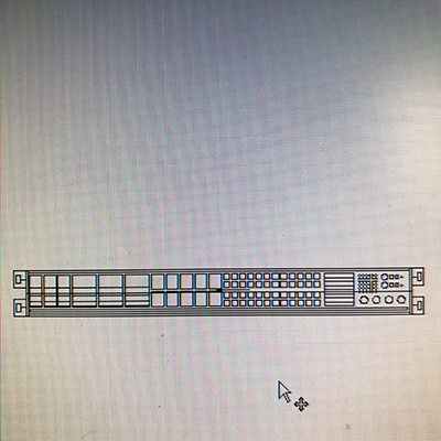
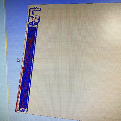
When all the toolpaths are calculated the vector looks like this:
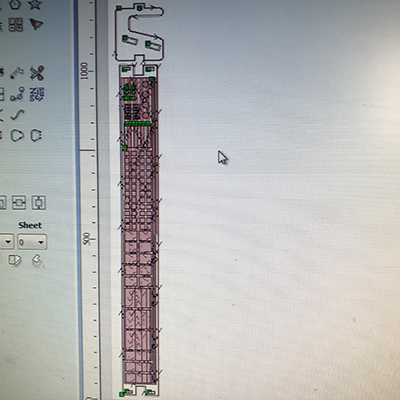
In the 3D view you can check all the toolpaths to see if you didn’t make any mistakes with pockets and profiles.
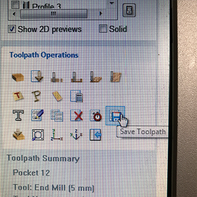
When everything is correct you click ‘save toolpath’ and save the g-code in a Shopbot format.
03 - preparing the machine
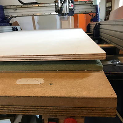
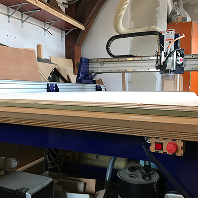
Put material on the bed of the Shopbot.
Even a big heavy piece of stock like I used can still be bent and not flat on the bed, that is why you screw the material down on the sacrificial layer.
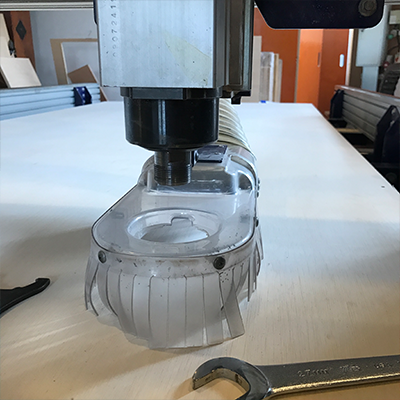
Once the material is on the bed, turn on the machine and software and move the head towards you so you can change the end mill.
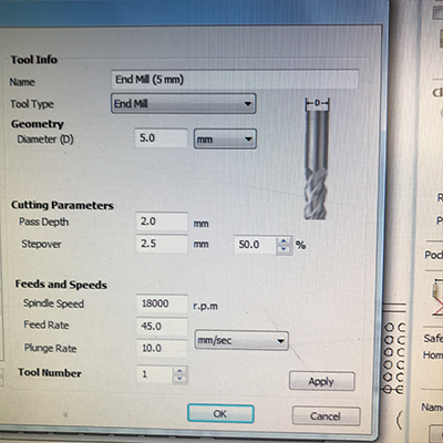
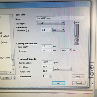
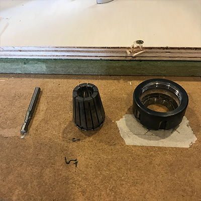
Lower the protective cover and unscrew the collet, find the right end mill for the job and screw everything back in. I used a 5mm flat head end mill.
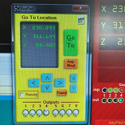
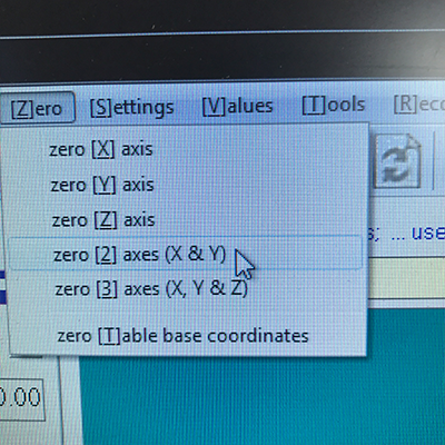
Now you have the right end mill and material in place, you can zero the machine, first zero the Z axis, this is an automated process on the Shopbot. Simply place the metal plate under the end mill and hit the Z button.
Zero the X and Y axes by moving the spindle to the right position and click ‘zero X & Y axes’ in the Zero dropdown.
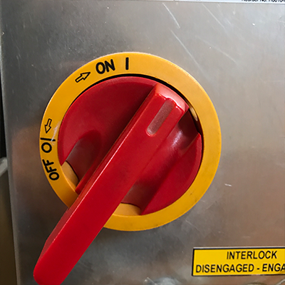
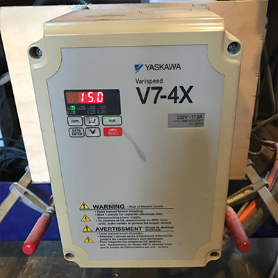
When everything is set, switch on the spindle by turning the key and let it run for about two minutes to warm up.
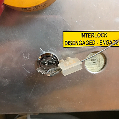
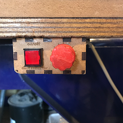
Before you start, turn on the ventilation.
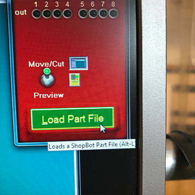
Double check if everything is good to go, load part file and hit start.
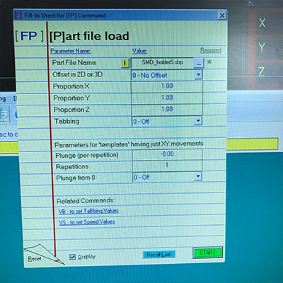
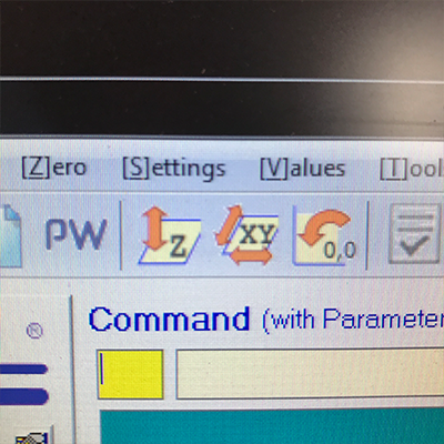
While milling you might hear a high-pitched sound coming from the machine, if this is the case, lower the speed of the spindle or the movement(or both). To adjust the spindle speed, hit space bar on the computer and then use this box to control the speed.
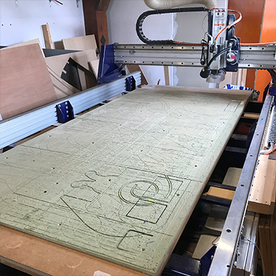
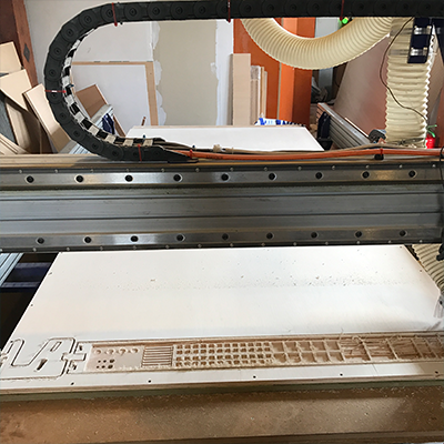
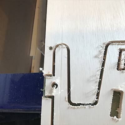
After the first run this was the result:
I should have zeroed my X axis differently as the mill left the material. If there was a screw in that place I would have had a big problem so I dodged a bullet with this part.
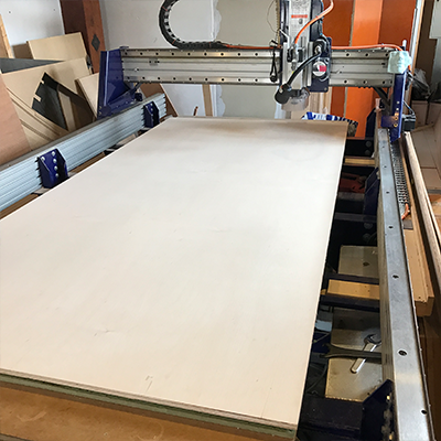
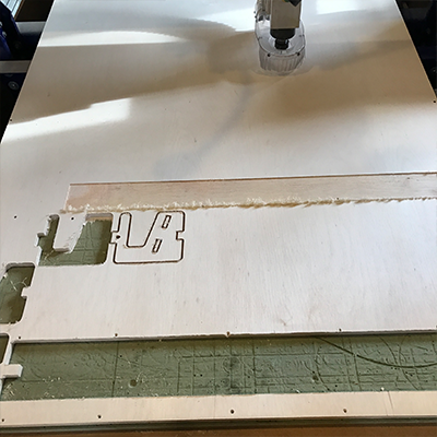
Another mistake I made was when I wanted to make a second piece, I set the material dimensions wrong and the machine started working too high on the material, leaving a big piece unused.
04 - hero shots
I made the parts-holder stackable so you can go as high as you want with this, or design different planks that all fit the same sides.
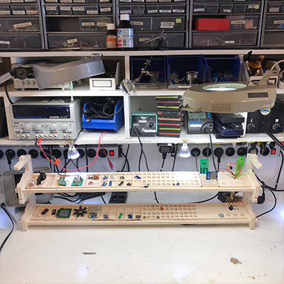
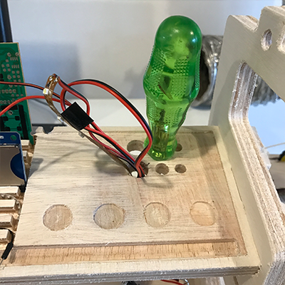
The different types of pockets hold different things like PCBs, screwdrivers etc.
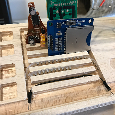
I need to do a better job on sanding and finish, but this is how it would hold really small parts.
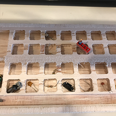
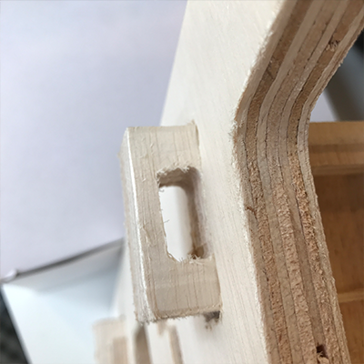
As I mentioned earlier, I forgot to add circles on the corners of parts that hold another part, which resulted in having to sand each hole, but in the end it fit.
board

side