Week 14 - Output Devices
Assignment
add an output device to a microcontroller board you’ve designed and program it to do something
Charlieplexed 7-segment LED digits
For this assignment I decided to make a 7-segment display with at least 2 digits, since this would come handy for my final clock project.
I spent some time going deeper into electronics, particularly understanding inductors, impedance, semi-conductors, and power-supplies. This site - Learn About Electronics had excellent explanations e.g. check out the section on Filter Circuits, it explains the role of reservoir capacitors very well. I also referred to classics like Art of Electronics and Practical Electronics for Inventors.
“Chalieplexing” stands for “Charlie Allen’s mulitplexing”, which allows fewer pins to be used to control many LEDs.
In Chalieplexing 2 LEDs are connected to 2 pins - one forward biased and the other reverse biased, so that by setting a pin high and the other low, current flows only in 1 direction - lighting up 1 LED.
To create 7-segment digits however you need to use multiplexing also because multiple LEDs (for each segment in a digit) need to be switched on at a time.
The way to do this is to have each use Charlieplexing to control a “common cathode” (or anode) line. To turn on some segment set the corresponding pins (you need 7 pins) to high, and the rest should be in high-impedance mode - this ensures that current flows for the required segments. Here are some nice explanations.
I started designing the schematics for a board with 2 digits. It turned out to be pretty complex.
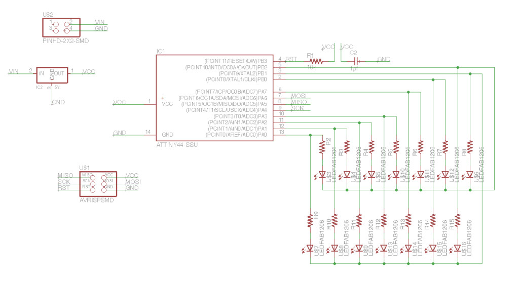
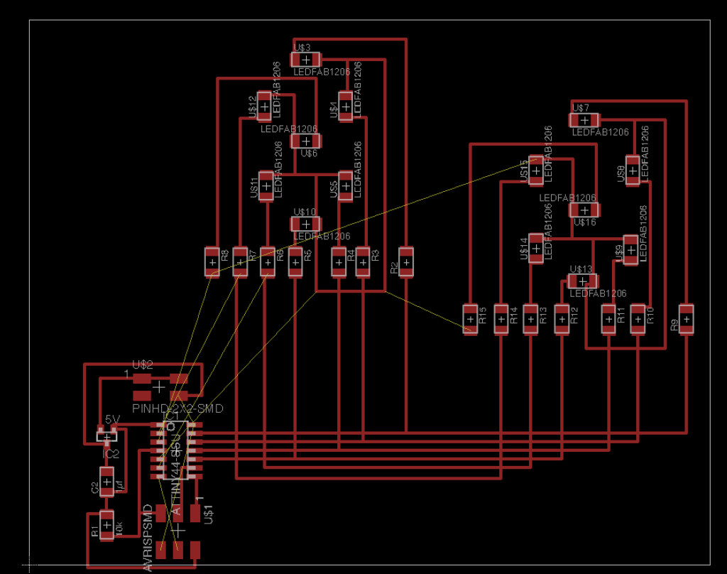
And the board layout was very hard to route without using multiple layers. Initally I was stuck trying to figure how to route all the traces. PCB Design Tutorial adviced to break up the board into logical blocks and then bring them together instead of trying to route everything at one time.
I followed this approach to route the digits independently first, and that seemed to be working well.
However, once the digits were done, it was near impossible to route the remaining traces without resorting to vias.
Here are the original files:
I was not keen to make a multi-layer layer board because the approach seemed wrong.
A better approach might be to create separate board for each digit, with its own microcontroller and serial interface which allows it to accept higher-level commands to display a digit. It would handle the details of manipulating segments internally. These modules could then be “networked” together with a central controller coordinating all the boards.
I liked this approach because it scales well with increasing complexity. I’ll need this for my final project, which requires an ambient light sensor, infra-red motion detection and 4 7-segment digits. Doing this as a network of modules would be a much cleaner approach.
With this in mind I’m now going to create a single 7-segment digit LED module.
7-Segment LED Board
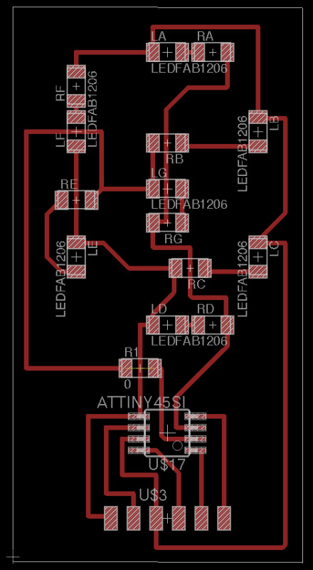
Here’s the new schematic.
I have also added an FTDI header for serial communication, to receive commands to display digits.
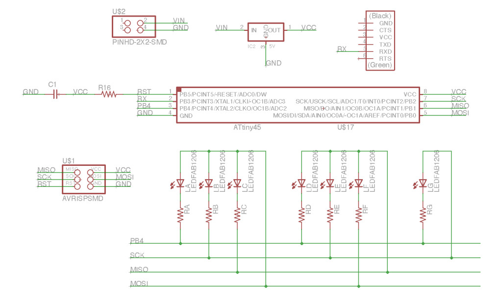
I have arranged the LEDs into 3 groups using 4 pins - 3 for LEDs and 1 for common-anode line. The last group has only 1 because only 7 are needed totally. This arrangement with 4 pins can drive upto 12 LEDs.
In each group 1 of the pins controls the common-anode line which is connected to all the LEDs in that group.
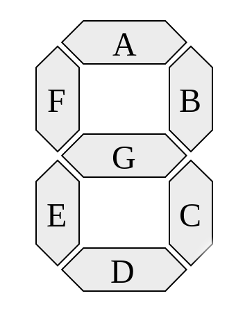
The resistors and LEDs are named according to the segments each drives.
I removed the ISP headers instead I’m piggybacking the ISP lines on the FTDI header.
I also removed the voltage regulator, since this board will be networked with a master-controller board which will provide regulated power.
Next I worked on the board layout. This took a few hours to get right because of all the criss-crossing wires and the common-anode traces.
Here is the board after milling and stuffing:
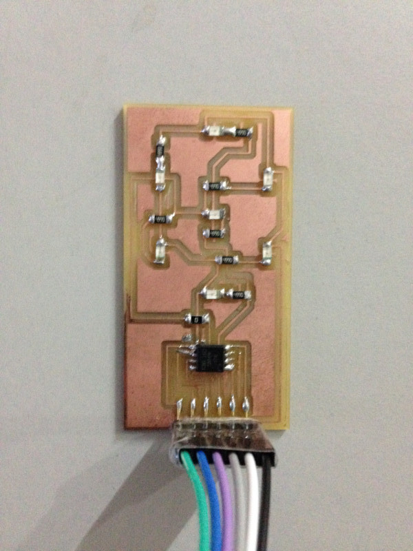
Next step is to program the board.
I wrote a simple program to blink the A (top) segment. Here is the output:
As you can tell segments B, C, D are also blinking, which should not happen! I’m still debugging this.
I hooked up the board to a DC power source to check if the voltage had anything to do with this. I recalled reading about the voltage range for LEDs being an important part of making charlieplexing work.
Sure enough it was the voltage. You can see in the video that at 3.3V only the B LED is visible, but C & E get gradually brighter as the voltage increases upto 5V.
Here is a great explanation of what’s happening: Charlieplexing LEDs: The Theory.
This graph from that article explains the trick, which is to ensure that the voltage lies in the range for the LED that needs to be lit, and at the same time is in the “no-glowing region” for the other LEDs which might get some current.
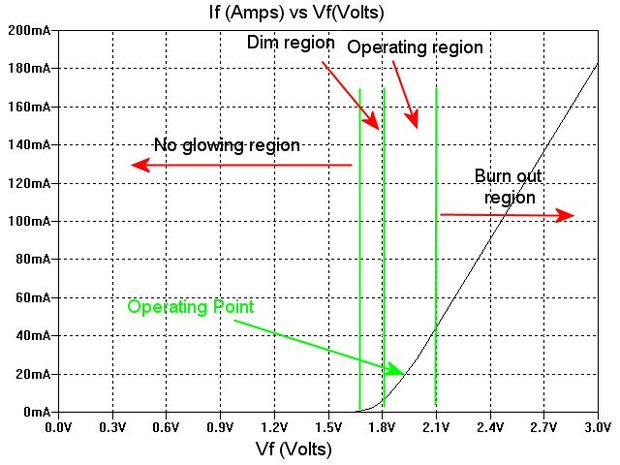
The operating range for the LED I was using seemed to be between 2.1 V - 3.2 V.
Here is the board displaying each digit from 0 - 9:
Original files:
Here is the code:
- Each digit is displayed for 2 seconds
- Each LED segment for a digit is switched on and off every 1ms
#include <avr/io.h>
#include <util/delay.h>

#define SCK_PIN PB2
#define MOSI_PIN PB0

#define ABC_ANODE   SCK_PIN
#define A           PB4
#define B           PB3
#define C           MOSI_PIN

#define DEF_ANODE   MOSI_PIN
#define D           PB4
#define E           PB3
#define F           SCK_PIN

#define G_ANODE     PB3
#define G           PB4

#define DIR_REG   DDRB

#define output(pin) (DIR_REG |= (1 << pin)) // set port direction for output
#define input(pin) (DIR_REG &= (~ (1 << pin))) // set port direction for input
#define set(pin) (PORTB |= (1 << pin)) // set port pin
#define clear(pin) (PORTB &= (~ (1 << pin))) // clear port pin

const int FLASH_DELAY_MS = 1;
const int DIGIT_DISPLAY_MS = 2000;

char DIGIT_SEGMENTS[10][7] = {
     {'A', 'B', 'C', 'D', 'E', 'F'},            // 0
     {'B', 'C'},                                // 1
     {'A', 'B', 'D', 'E', 'G'},                 // 2
     {'A', 'B', 'C', 'D', 'G'},                 // 3
     {'B', 'C', 'F', 'G'},                      // 4
     {'A', 'C', 'D', 'F', 'G'},                 // 5
     {'A', 'C', 'D', 'E', 'F', 'G'},            // 6
     {'A', 'B', 'C'},                           // 7
     {'A', 'B', 'C', 'D', 'E', 'F', 'G',},      // 8
     {'A', 'B', 'C', 'F', 'G',}                 // 9
};

int DIGIT_NUM_SEGMENTS[] = {
    6, // 0
    2, // 1
    5, // 2
    5, // 3
    4, // 4
    5, // 5
    6, // 6
    3, // 7
    7, // 8
    5  // 9
};

int anode_pin_for(char led) {
    if (led == 'A' || led == 'B' || led == 'C')
        return ABC_ANODE;
    else if (led == 'D' || led == 'E' || led == 'F')
        return DEF_ANODE;
    else
        return G_ANODE;
}

int led_pin_for(char led) {
    if (led == 'A' || led == 'D' || led == 'G')
        return PB4;
    else if (led == 'B' || led == 'E')
        return PB3;
    else if (led == 'C')
        return MOSI_PIN;
    else // 'F'
        return SCK_PIN;
}

void high_impedance(pin) {
    input(pin);
    clear(pin);
}

void flash(char led) {
    int anode_pin = anode_pin_for(led);
    int led_pin = led_pin_for(led);

    output(anode_pin);
    output(led_pin);

    set(anode_pin);
    clear(led_pin);

    _delay_ms(FLASH_DELAY_MS);

    high_impedance(anode_pin);
    high_impedance(led_pin);
}

void flash_segments(char segments[], int len) {
    int i;
    for (i = 0; i < len; i++) {
        flash(segments[i]);
    }
}

void display(int digit, int duration_ms) {
    int i;
    char *segments = DIGIT_SEGMENTS[digit];
    int num_segments = DIGIT_NUM_SEGMENTS[digit];
    int cycles = duration_ms / (FLASH_DELAY_MS * num_segments);
    for (i = 0; i < cycles; i++) {
        flash_segments(segments, num_segments);
    }
}

int main(void) {
    int i = 0;
    while(1) {
        display(i, DIGIT_DISPLAY_MS);
        _delay_ms(1000);
        if (++i >= 10)
            i = 0;
    }

    return 0;
}