Assignment
Make a machine, including the end effector, build the passive parts and operate it manually.
Learning outcomes:
- Work and communicate effectively in a team and independently.
- Design, plan and build a system .
- Analyse and solve technical problems.
- Recognise opportunities for improvements in the design.
Tasks:
- Explained your individual contribution to this project on your own website on the group page, has your group:
- Shown how your team planned and executed the project.
- Described problems and how the team solved them.
- Listed future development opportunities for this project.
- Included your design files, 'hero shot' photos of the machine and a short video of it operating.
This being a group project and since our Trivandrum fablab have 14 fab academy students, there where two groups formed for the group assignments ie, namely Team A and Team B. Our group name is "Team A".
Our Team Members are:
A few ideas were discussed which includes our team:
- Plotter
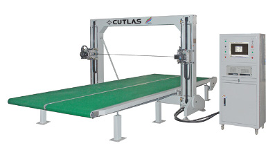
- Foam Cutter
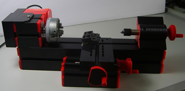
- Mini CNC Lathe

- CNC Plotter
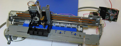
After the group meeting held on 2nd of April noon, we decided to go forward with Mini CNC Lathe. Since the entire machine need not be made from scratch, it was decided to build up on the machine from the present designs available. Sibu and a few others made a trip to the junkyard to bring in a few components needed. At the end, we pooled a few resources. There are a few parts which need to make from the lathe, including the Headstock with a chunk to hold the tool, a motor to power up the spindle, a tool post that can move both X and Y directions and optionally a tail-stock to support the workpiece.
Lathe
A lathe is a machine tool that rotates the workpiece on its axis to perform various operations such as cutting, sanding, knurling, drilling, or deformation, facing, turning, with tools that are applied to the workpiece to create an object with symmetry about an axis of rotation.
 Parts
Parts
Chuck will hold the workpiece and will be attached to a Drill or some other motor or Dremel tool. But Dremel may not have the sufficient Torque for the purpose, it definitely has the speed.
Me, Nisha, Jaseel and Sibu 3D printed the chuck parts using the the two 3D printers here. The three drive gears were printed using Dimensions SST 1200 es. We decided this so that the drive gears would be more stronger compared to printing using PLA plastic in Ultimaker 2 (we did not have ABS plastic spools for Ultimaker 2 in our inventory). The files for the chuck was taken from thingiverse.
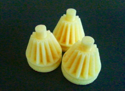 Gear Drive printed using dimensions
Jawed chucks
This is a self-centering chuck, also known as a scroll chuck.
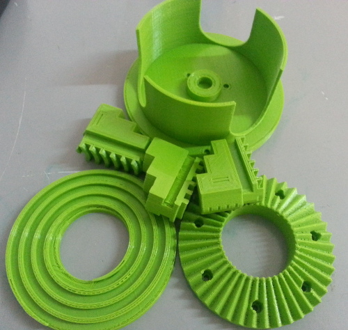
There is a front housing component also of the chuck to be printed. A chuck is a specialized type of clamp. It is used to hold an object with radial symmetry, especially a cylinder. In drills and mills it holds the rotating tool whereas in lathes it holds the rotating workpiece. On a lathe the chuck is mounted on the spindle which rotates within the headstock.
We are planning to laser cut the base and the staging box, Mr.Sibu is preparing the CAD files for it.
Assignment
Automate your machine. Document the group project and your individual contribution.
This week's assignment is to automate the machine built, and document the whole process in group and individual pages.
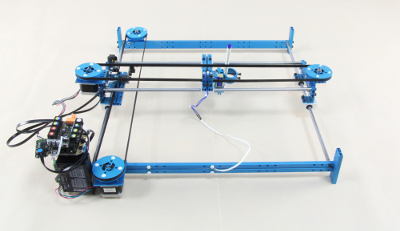
Since, our building machine was lagging the first intent was to complete it. We had to laser cut the box for the two stages intented for X and Y movements. Modular stages allows users to explore different kinematic models easily. Different heads can be mounted to them. So, we decided to focus first on building the two axis machine that can hold a tool and could be automated.
Once the stages were build, we decided to implement the catchup plan first which was to make the plotter. Later, the same 2-axis machine could be used with a different tool to create different machines and the plotter pen could be replaced with the Lathe tool.
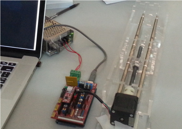
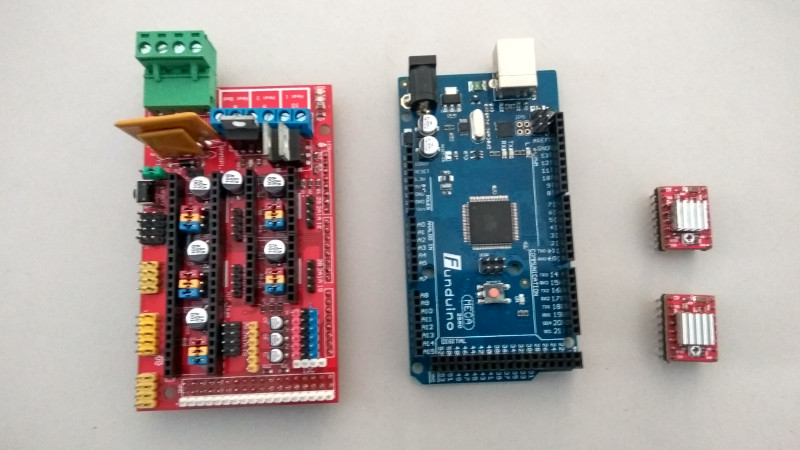
This week we are supposed to focus on the automation part of the machine. We did not have Gestalt boards or the MTM stages in the lab. A gestalt board is a single stepper driver that is used to control a stepper motor by the PC. Since fabrication was taking time, it was decided to use RAMPS. RepRap Arduino Mega Pololu Shield, or RAMPS for short is designed to fit the entire electronics needed for a RepRap in one small package for low cost.
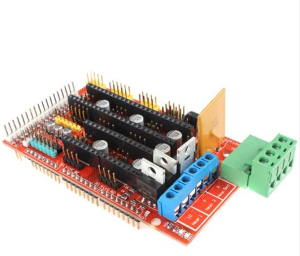
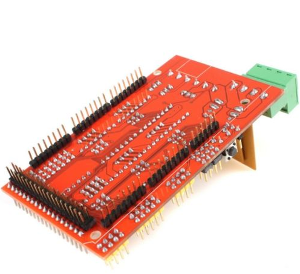
The first step was to check if RAMPS was working fine and could move a single stepper motor. At first we connected the board and motar and used RAMPS test code to test it.
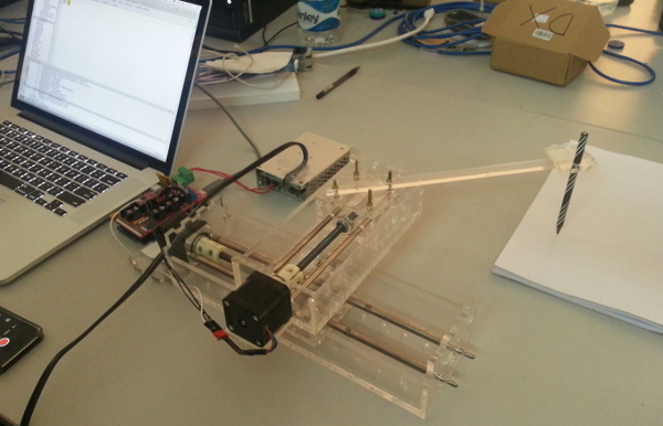
The modified version of the code was used. With the modified code working good to achieve the stepper movements, next step was to control the machine with instruction sets provided so that the motors could move the plotter head as per the instructions given. It was decided to implement a simple G-code interpreter, which would run on RAMPS and communicate with a host using a serial interface.
Final assembly of machine
A lathe is a machine tool that rotates the workpiece on its axis to perform various operations such as cutting, sanding, knurling, drilling, or deformation, facing, turning, with tools that are applied to the workpiece to create an object with symmetry about an axis of rotation.
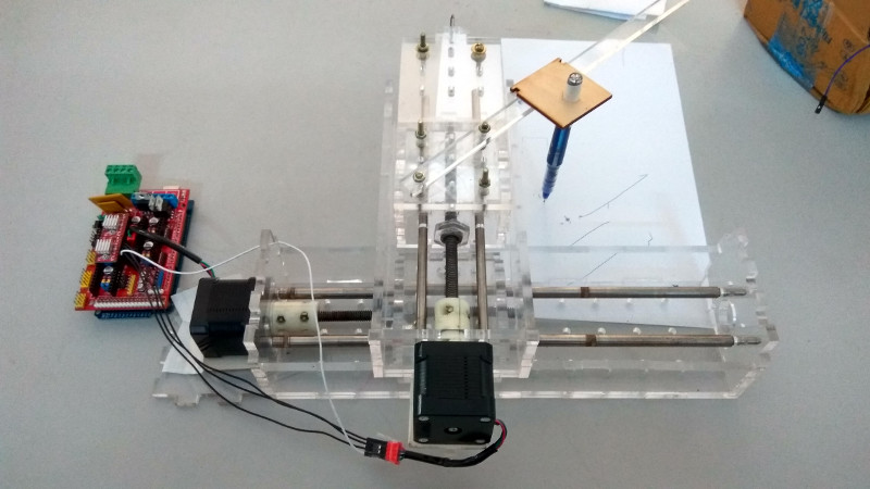
Initially we planned and started working on developing a small lathe, but for developing such a lathe is so difficult in a short duration, we changed to make first a small pen plotter.
My Contribution
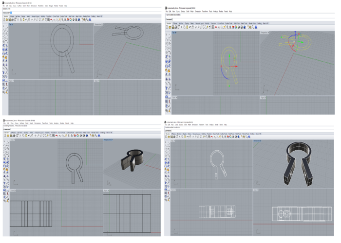
All the mechanical design parts were designed by sibu, I thought to design a pen holder for the plotter. For that I have checked some of the available pen holder designs over the Internet and I got an idea of how to make a pen holder. I started designing in rhinoceros and the design is shown here. But unfortunately our team members told to go with a simple pen holder in acrylic sheet. So we had made a simple pen holder.
From the machine design week I learned so many things, how effectively utilize the scrap machines and all.
Making of pen holder in "Plotter".
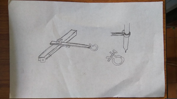
Design in Rhino software
The design I made is a pen holder and is as shown.
Download My Design File :
Pen Holder Rhino File