Goal
This week’s goal is to get to know about all the design tools which can be used for designing the final project. This covers both 2D and 3D designing, rendering, simulation etc.
During this weeks lecture Niel went through all the softwares listed in the fabacademy and gave a brief about each of them. I looked through all of them but unfortunately many of them were only for Windows or mac. I have a Linux system so my options came down to a few but good ones.
2D design
- Raster
Gimp
I am using GNU/Linux for the last couple of years. So for photo editing and drawing purposes I have been always using Gimp. It is a powerful alternative for photoshop. I use it primarily for resizing the pictures, changing colour schemes, etc.
- Vector
Inkscape
It is a wonderful tool for drawing vector graphics and for editing things drawn in other proprietary softwares. I have been using this tool during Pre-Fab and later while working with Laser cutter.
I made the design of a tool for measuring the clearance of my motorbike suspension. It is a measuring tool which I am plan to be make out of acrylic. I will use the design to cut the acrylic using laser.
Design File of Inkscape .svg

3D design
The design type I liked the most is constructive solid geometry as I believe it gives detailed know-how if what you have designed. It gives more flexibility while designing and also easy to make changes later.
Tinkercad
It is the best tool for beginners. You can make a 3D structure in minutes. I had no prior experience of designing in 3D and successfully created my first model in no time. So I recommend this to every one who is looking for something to start - this is it !
Starting off is easy just sign-up and their is even a learning lesson for designing a shape with given instructions. I tried that and then used the shapes to make a FABLAB 3D printable sign board.

Blender
Blender has come a long way from what it initially was. I had tried it out of curiosity a few years back. There are many tutorials available in youtube for starting off. It is easy to install in Ubuntu as it is available in the software center. Check out their Youtube channel, it’s awesome.
OpenSCAD
OpenSCAD is different from blender in a way that it concentrates more on the CAD part than the artistic like in the later. It is a free software and is available across Linux, windows and OSX. The hard part I think is that it is not an interactive modeler but a software which compile 3D models from written scripts. We can work with Constructive modeling and/or extrusion techniques. I have tried to make a model of a chair for week 7.
This tutorial helped me in learn the basics of working with it. The design of the stool included the following Steps
- make the basic plate without the cutouts into a
module. Make it parametric by giving theheight, width and thicknessas variables. - make two copies of the same plate and
translateit to have them perpendicular to each other. - for making the top and bottom cuts take the
differencebetween the plate and two spheres places accordingly.
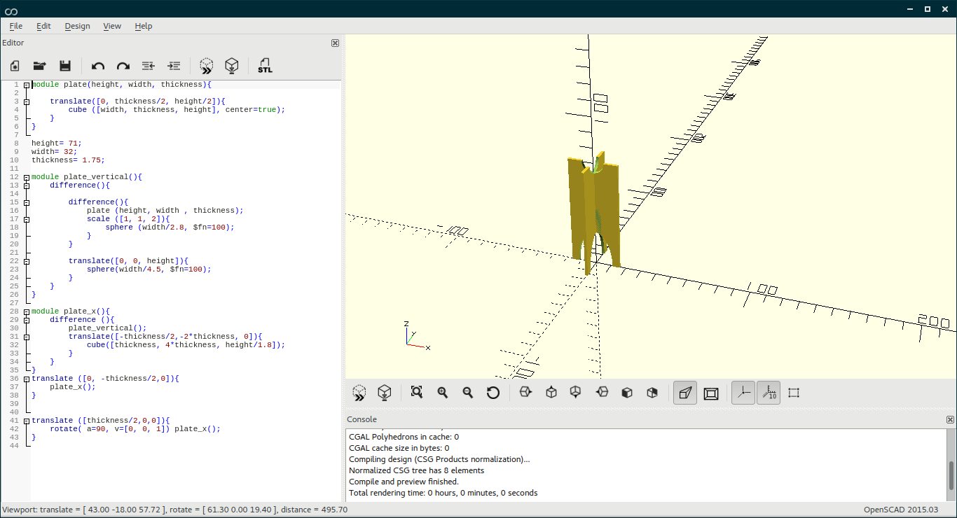
Here is the script written for the same1
2
3
4
5
6
7
8
9
10
11
12
13
14
15
16
17
18
19
20
21
22
23
24
25
26
27
28
29
30
31
32
33
34
35
36
37
38
39
40
41
42
43module plate(height, width, thickness){
translate([0, thickness/2, height/2]){
cube ([width, thickness, height], center=true);
}
}
height= 71;
width= 32;
thickness= 1.75;
module plate_vertical(){
difference(){
difference(){
plate (height, width , thickness);
scale ([1, 1, 2]){
sphere (width/2.8, $fn=100);
}
}
translate([0, 0, height]){
sphere(width/4.5, $fn=100);
}
}
}
module plate_x(){
difference (){
plate_vertical();
translate([-thickness/2,-2*thickness, 0]){
cube([thickness, 4*thickness, height/1.8]);
}
}
}
translate ([0, -thickness/2,0]){
plate_x();
}
translate ([thickness/2,0,0]){
rotate( a=90, v=[0, 0, 1]) plate_x();
}
Design fiel of OpenSCAD
Antimony
Antimony is a software which is derived from Kokopelli, which is a script based CAD/CAM written in Python. In kokopelli we have to write code in Python for designing. Antimony uses something called nodes which is connected to form solid models.

Further as it make use of constructive solid geometry philosophy and it is very powerful in modifying the design parameters at any point during the development.
I was introduced to the software during Pre-Fab.
- Installing antimony.
It is no easy task and after several forking and re-tries only I was able to get it up and running. The process I followed is in here. Please note that after getting all the dependencies installed, while giving themake -j8command you might face failure error message. Instead usesudo make -j8which actually worked for me. - Running antimony.
Navigate to the directory where antimony is installed. Then navigate to build/app and open a terminal in there. give the command./antimonyand it will be up and running.
My project designs
I prefer to draw on paper for visualizing the project than using a 2D modeling software. I feel constrains while using most of them and it takes a great deal of time to master one. And if by some means we don’t get that software we are doomed. So I still prefer old school hand drawings.
I has just started working on making the 3D model for my final project project. so this is a work in progress.
Design file- casing CAD File
Steps in designing
- open antimony and add from add->2D->rectangles->rectangles with rounded corners (center)
- give the required dimensions for the rectangle, here it become the base of the socket.
- again add another rectangle within the same with all dimensions reduced and take the difference of both. Now under add menu under 2D-3D->Extrude and connect the node from difference taken earlier to this. Give the required height in the zmin and zmax columns respectively.
- add another rectangle at it’s zmin and merge the entire parts together to form the base of the power socket.
- Similar manner I also designed the cap for the power socket.
