This week we are supposed to make something BIG using the CNC machine available in the labs. We have two of its kind
- Modella - it is a small machine which we us primarily for milling PCB boards. It can also be used for milling on machinable wax for making cavities for molding and casting. The end mills used here are of small diameters. In our lab we have two types -1/32th inch and 1/64th of an inch.
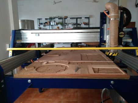
- ShopBot - it is a large milling machine with end mills ranging from half of an inch to 1/8th of an inch. It can be used for working with timber, plywood, soft aluminum and in limited on other metals. It is a 3-axis machine and has a bed size of 4x8 feet. One of the cool feature of this particular model is that it is very modular ie, it can be dissembled and moved to some other location and reassembled again there easily. So it is somewhat mobile.
Notes from this weeks lecture.
For this week I am planning to document the notes I have prepared during the weekly lecture. I will include things which I feel are important. I have a very volatile memory, so this should be useful for me. It can also be referred by anyone anytime for clearing doubts.
Note: The following notes are prepared with ShopBot in mind. But most of the topics are generic in nature.
Tooling
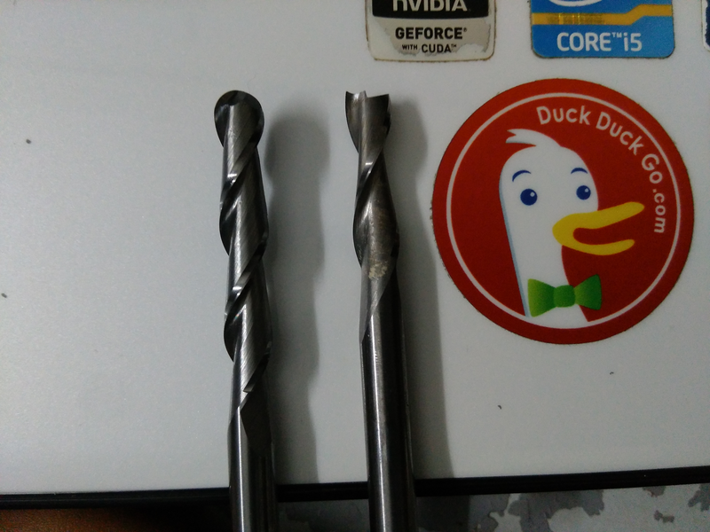
- drill bit vs end mill :- drill bit can be differentiated by its pointed tip which is for drilling into the object where as end mills have flat tips and they are for milling away chunks from the object. End mills give a flat cut while drill bit gives a curved cut.
- flutes :- they are the spiraling sharp part along the surface of an end mill. They are for cutting through the object and for clearing the chips. Less number of flutes means chips will be cleared easily but the cut will be of rough finish. Higher the number of flutes we will get a smooth finish but the chips cut off wont be cleared effectively.
- coating :- the end mills undergoes a lot of stress and strain while milling. So to provide extra strength, it is very common, to coat the bit in some ceramic like nitrites which increase their endurance.
- center cutting :- when you hold the bit upside down an look, if the flutes meet at the center then it is center cut and is good for cutting downwards but not for clearing the debris. If the flutes terminate before reaching the center it is non-center cutting and it is good for clearing the debris but not good for cutting downwards.
- up/down cut :- if you hold the end mill by its head (the portion without flutes) and rotate it clockwise if you get the impression that the flutes are spiraling up then it is up cut and if it feels like it’s spiraling down then it is down cut. Up cut is good for clearing the debris easily but results in a rough top surface while down cut is bad at clearing debris but gives a smooth top surface. Then there is something called center cut, where from bottom till middle it is down cut and from there till top it is up cut. This gives smooth top and bottom surfaces but very bad at clearing the cut out chunks.
- flat/ball end :- flat end leaves flat surface and steps are formed when used for making cavities. Ball end leaves curved surfaces and forms curved finish while cutting cavities.
Speeds & feeds
- Chip load :- This is the amount of material that is removed in each chip. The value is approximately = feed rate (inches per minute) / (RPM x number of flutes)
- Cut depth :- This is the measure of how deep the end mill should go in each step while milling. To be more clear, understand that these machines mill step by step, they go to a certain depth first and do the entire milling once and then move to the next step and repeat till it reaches the point we specify.
- Step over :- While milling a pocket, the surface will be divided into spiraling lines through which the end mill travels. While doing this the step over determines how much the adjacent path make the end mill cut to overlap each other. Usually we use it at 50%, ie the adjacent end mill cuts will overlap 50%, which gives a better finish.
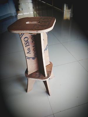
The Fab Stool.
We have a shortage of furniture in the lab as the number of participants are comparatively high. I decided to make a stool using plywood with press fit technique. Most of my classmates are also making some kind of furniture too.
Preparing and testing the machine.
Before starting the design, we tested different parameters of ShopBot and the plywood we have. We have end mills of 1/2, 1/4 and 1/8 diameter. Each have upcut, downcut and ballnosed end mills too.
Yadu made a design for knowing the right slot size for press fit. As we have 12mm and 20mm thick plywoods, the design was made accordingly.

The Design
I made the design in OnShape. I designed it in a modular way. It had mainly 4 parts
- 2 legs with a bottom cut slot
- 2 legs with top cut slot
- a part for resting the foot
- the seat

The two pairs of legs, one with bottom slot and the other with top slot, can be brought together to fit into single structure. The slot size is 19mm as I used 20mm thick plywood.
The foot rest can be inserted from the top and when pushed down, as their is a gradual increase in the size when coming downwards, at one point it will fit tightly to the frame. It was tricky to find the actual size of the slots so that we get the required height.
The seat has 4 pockets on one side which can accommodate the top ends of the legs. Once fitted their wont be any sign of slots or pockets on the visible surface.
Mistakes
I made at-least a dozen or so mistakes while doing this assignment ! Most of them are stupid or foolish or both. I will share a few of them
The outer and inner cut- While giving the tool path we should be careful in specifying whether to have inner or outer cut. If wrongly given we will have either bigger or smaller slots.
Because i gave the path as outer cut the seat portion was not cut properly. So as you can seeThe rpm, plunge rate and Feed rate- If we get these values wrong either the bit will break or the material gets damaged. So keep a note to have the values under the threshold for proper cutting.Zeroing the 'Z'- If we get this wrong the bit might eat into the sacrificial layer or chances are high that you get your bit damaged.Holding the work piece- This is a very important check box to be ticked before starting the work. If we don’t hold the material firmly to the base all sorts of error occurs.