This week is dedicated for playing around with controllers, processors etc- things which can be programmed to do stuff, things which are like mini computers. The most common microcontroller in our FabLab is the ATTiny series. We also have Atmega 328P, Atmega 32U4 and ARM STM32F103C8T6. They are all AVR microcontroller’s, except the last one, and we will be programming the board we made in Week 4- Electronic production.
As we recall, in that week we made an echo
-hello board with ATTiny44 microcontroller which can be programmed using the Fab ISP. The board we modified had an additional LED and a button/press switch attached. So we can program the board to do some basic tasks like blinking the LED and recording a switch press etc.
Notes
Programming
I programmed the AVR in two different ways.
- Using Arduino IDE.
- Using AVR-C.
Arduino IDE
Most of the people reading this documentation should be knowing what is Arduino or even to work with one. This Link will welcome you to the world of Arduino and DIY projects using it.
As I am using Arch Linux I used AUR to install the arduino IDE. So I have the latest version (1.6.8) of the same.
I followed these steps of adding the ATTiny chips into the Board list in the IDE which come under the Tools drop-down menu. Next i had to figure out the pin to which the LED is connected. It is nice to have the Data Sheet handy. It will come to your help many a time. For the present usage we just need the following diagram to get the PIN number for coding.

With the help of both the pin-out image and the data sheet I wrote the following piece of code for blinking the LED continuously for with a time interval of 1 second.
1 | /* |
After this I wrote a program to turn the LED ON and OFF with the switch connected to pin 7.
1 | /* |
AVR - C
Blinking
I tried to have an IDE for working with AVR - C as I am used to one. So decided to try Code::Block. But after spending an unsuccessful half an hour trying to get the compilers, debuggers etc right I got fed up. So I uninstalled the program and decided to go with the text editor Vi, which I have just started using or Atom, which I think is more realistic as it has syntax highlighting and all.
This way of programming will definitely need the help of datasheet as we need to get data like the number of ports, pin numbers, internal architectures, information on registers etc. So keep it by your side.
The first attempt was to write the code for blinking the LED. After a few hours spent on internet reading and watching tutorials in youtube, the following is what I came up with.
1 | /* |
Add a button
Then I added a control of switching the LED ON and OFF according to push of a button.
1 | /* |
Things to know here are the logical AND and OR operations, Also out the registers of the PORT A&B and PIN registers. Here are the direction registers, input registers and the data registers of port A&B 
 .
.
Interrupt programming
Next i aimed at understanding interrupts in AVR programming. Atmega has different size timers/counters in it which can be made used to make different applications like stopping/pausing in between processing to run a different code, make PWM waves etc. Here i will be using the counter and interrupts to blink two LEDs alternatively with a time interval of 1s. Lets sbegin by usign timers and registers to create interrupt driven processes in ATTiny 44.
Their is provision for 8bit and 16bit timer/counters in tiny44. Timer/Counter0 is a general purpose 8-bit Timer/Counter module, with two independent Output Compare Units, and with PWM support. It allows accurate program execution timing (event management) and wave generation. The 16-bit Timer/Counter unit allows accurate program execution timing (event management), wave generation, and signal timing measurement. I used the 8 bit counter.
Working
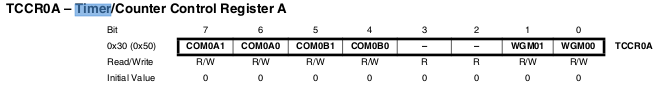
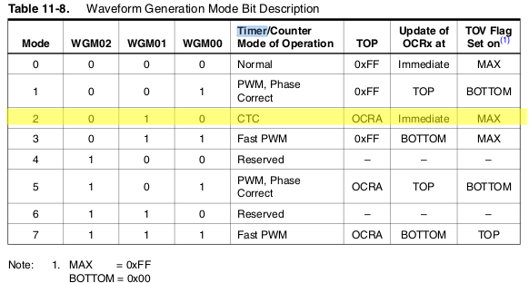
There are different ways for configuring the counter. The basic thing to know are, an 8-bit counter can count from 0-255 and if the prescaler is set to 1 the value changes in every clockcycle. Once it reaches 255, in the next clock the counting register wlll be flushed and reseted and a bit in the SREG will be changed indicating the overflow. We can have an interrupt that way or tere is an option for haveing an 8-bit number stored and being compared to timer value and then call an interrupt when they become equal. I chose the second method for my program. Some of the importanat registers to be noted are

I prescaled the clock source to clk/1024 to have maximum time out of one full count.

The code i wrote for blinking the led alternatively using interrupts is
1 | #include <avr/io.h> |
things to learn
- using timers for making PWM signals
- understanding the ADC functionalities of the microcontroller