MECHANICAL & MACHINE DESIGN
Machine Design
This is one of the most important and interesting task we have in our fab academy course , that is to design a machine by ourselves. The best part is that we do it as a team and this combines everybody's strength and gives us the opprotunity to work as a group.
The entire class was divided into two groups, and I am in Team2.
Our Team - THE TEAM2!!
I was lucky to be in a group of very active and passionate people with various strengths, and let me tell you it was an awesome experince to learn some thing new and special from each of them, well let me introduce them to you..
1. Kavita Arora
2. Muhammed Safwan
3. Nadeem Ahmed
4. Puneeth Raj
5. Vishnu Easwaran E.
6. Yadu Sharon M. G.
7. And me :)
Puneeth Raj was designated as the team leader
CHOCOPLOT, The Chocolate Plotter!!
Yes, as the name tells you it is a sweet machine that can design choclate plots :-) Before I tell you the story how it evolved, let me show you the heroshot of our Yummy Machine ;-) .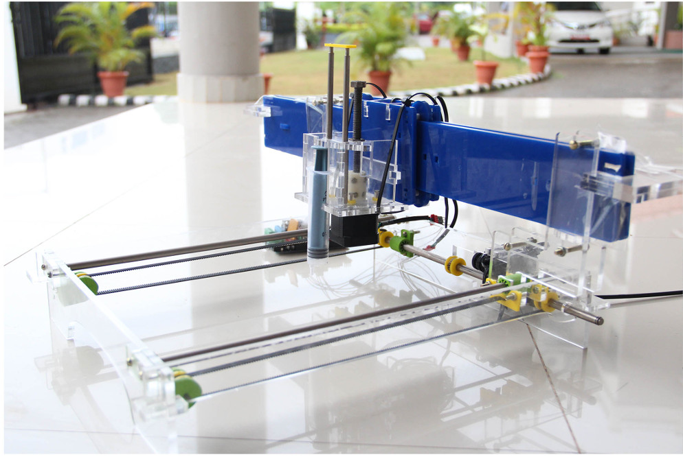
The Story Behind CHOCO PLOTS evolution!!
There were 14 of us in our fablab and Fracisco divided us into two groups who will be working on two different machine projects. Puneeth was appointed as the leader for our team. Francisco further added the following optional rules to make things interesting.
Rule 1 - All the mehanical components should either be fabricated or salvaged.
Rule 2 - The machine should be simple and often created machine such as pen plotter etc
On day One we all gathered and discussed on what projects we can work on. The following areas were identified to be further explored.
After getting a good idea about what each of us is capable of, Puneeth lead us through an exercise for generating ideas. We were asked to generate as many ideas as possible in 5 mins. The nature of the ideas could be abstract, it could include, feelings, phrases, ways of fabricating, name of machine, anything that comes to our mind unfiltered and without judgement. A bunch of great ideas popped up because of this. This way of idea generation leads to most interesting ideas and involves creative thinking.
We had Initial unfiltered Ideas about 100 ideas in 5 mins..Some of the interesting ideas that our group came up are,
On day two, we selected the following as the most feasible projects to discuss further..
After spending a goodtime on discussing about each project, we concluded that, Time writing bot is too simple and material are available and can be fabricated in no time. The wall climbing bot require a lot of work and maybbe beyond the scope for the time being. Laser cutter was interesting for all of us but we didnt had a appropriate laser source. The Dosa maker seems too complex a problem to start with which involves heating, rotation and many other complex things which are ofcourse interesting to do but can not be done over such a short period of time.
The Component selecting bot became our favourite, we felt it as a doable one with integration of linear stages and design of end effector. Unfortunately we did not have any mechanical components for fabricating Nadya's cardboard linear stage directly. We didnt had the linear bearings, threaded rod, nylon bushes and motor-shaft couplings!! But finally we gave up that and selected the Chocolate plotter, which transformed to CHOCOPLOT!!
A QUICK SUMMARY ON DEVELOPMENT!!
A detailed explanation of the development of CHOCOPLOT can be found from this link..
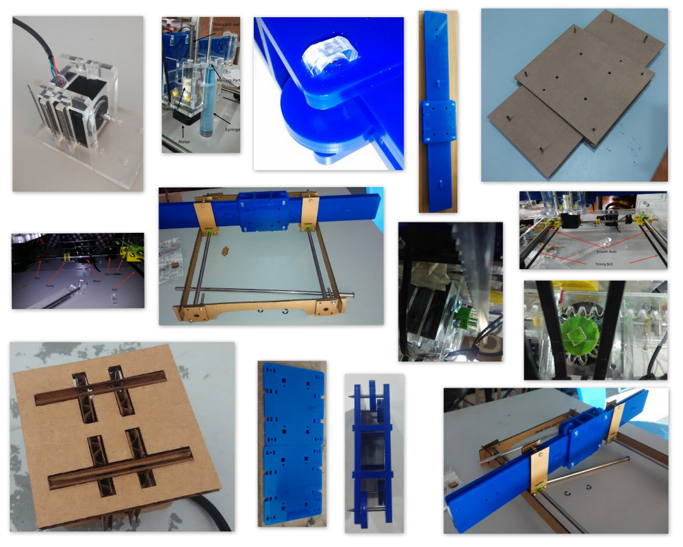
A bird's eye view on the Various modules our team developed..
And here is a quick video on how this works..
MY CONTRIBUTIONS
Now let me switchover to my contributions in this, I mainly had two different jobs to do other than assisting the whole thing..
Well as the title says, I was responsible to give inputs to the group from a customer perspective about how this proto should evolve, what features it should have, how user friendly it should be and so on..
The second and third roles I volunterily took over as I and Yadu was planning for developing our own Interface & control mechanism for the plotter. We were quite ambitious to make our own with the following things in mind .
Yadu Started working on the Host MIcrocontroller and stepper driver part and I was into desiging a communication system and PC based custom interface software.
Here is a link to Yadus Board under developement!!
Since I was accustomed to making Custom front end softwares I first concentrated on the Hardware communication mechanism.
As we thought of a roboust multi node network based architecture, RS485 communication was my choice. The main reasons being,
MAX489 DRIVER - SAMPLES FROM MAXIM INTEGRATED
I had requested for samples of MAX489 from Maxim Integrated, they have been kind enough to send them, though I had some trouble for clearing the customs formalities of our country, its a pain worth taking to get some of the latest chips coming out from the factory even before them reaching the market. Thanks to MAXIM INTEGRATED for this and my experiments began with it..
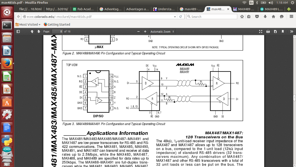
MAX489 is a Full Duplex Tranceiver capable of supporting upto 32 Nodes, More about the MA489 can be reached from its datasheet from this link..
Basic MAX489 Connection configurtion is as shown..
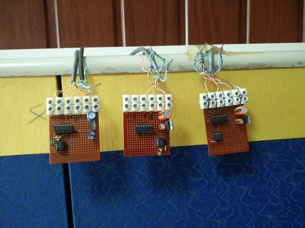
Since We dnt had much time I assembled the MAX489 drivers to a Common PCB as shown..
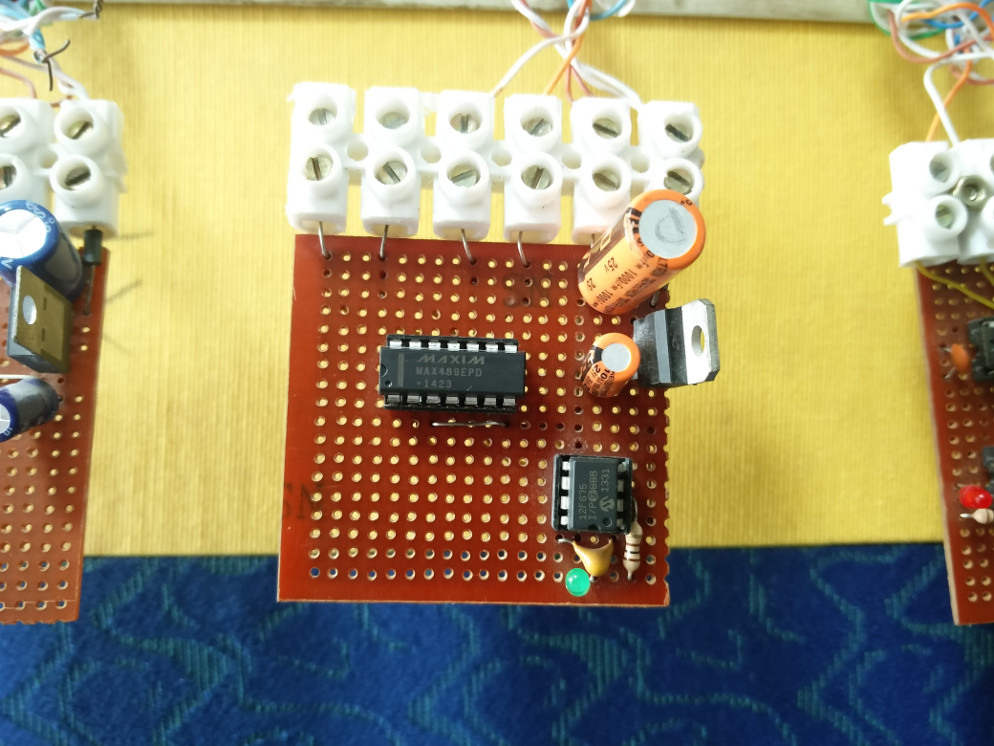
As a network was what I had in mind, to emulate the same I chose PIC12F675 Microcontrollers to function as Nodes, you can find them hooked to the MAX489 ICs..
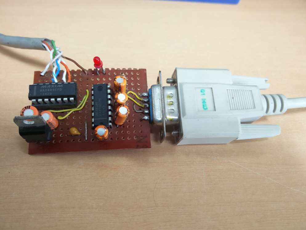
This is the PC end Tranceiver part..
A PREMATURE HALT !!
Though the custom interface was progressing well in its development and Yadu also on the other side developing the Host controller board, We had to take a tough decision to temporarily stop the development of this board and interface as we were running out of time. We decided to switchover to Arduino with RAMPS motor shield and Marlin firmware for the time being.
I will continue its development as time permits more over the host controller is also half cooked so we want to get this up and running at a later time at least. For the rest of time, I will be assisting the assembly other developemnt activites to complete the plotter..
All the design files I tried can be downloaded from here.
Opportunities for improvements in the design
In future after we complete this basic version of Hardware and Custom Sotware, I would like to design wireless nodes and design them in such a way that every node will be a addressable Identical wireless entity with particular motor driving and feed back capabilities. I shall look forward to working on this if time permits during the Networking week.