
INPUT DEVICES
In the world of microcontrollers, an input device is a peripheral ( an external circuit or sensor ) used to provide data and control signals to the information processing system of the microcontroller . Examples of input devices include a simple button, various sensors capable of measuring light, sound, pressure, motion, temperature, chemical concentrations etc.I will be using a couple of input devices/ sensors for the fab project such as,
After exploring all the above mentioned modules which will be incorporated in my final project , For this week's assignment I am only using a commonly available temperature sensor LM35 to document.
For interfacing LM35 I am designing a custom tiny input board based on PIC12F675 Microcontroller. The ADC module of the microcontroller is used to read the analog values from the sensor and temperature is computed with the help of the software. Since the microcontroller has got only 6 pins other than POWER inputs I thought of packatizing the computed data and send them to PC as serial data. Keeping this in mind I ordered the Controller and designed the board also. But I missed to remember the fact that this controller doesnt have a UART module inbuilt so I am making use of a software UART and sending the data to the PC using a USB to UART TTL Bridge Cable at 1200bps.
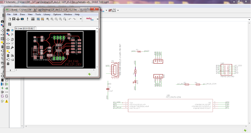
INPUT Device PCB - SM_FAB PIC12F
I started by making my custom PCB by keeping in mind to make a generic development board so that I can use of for different purposes..
Main features I wanted this Board to have are,
Here is how it evolved..
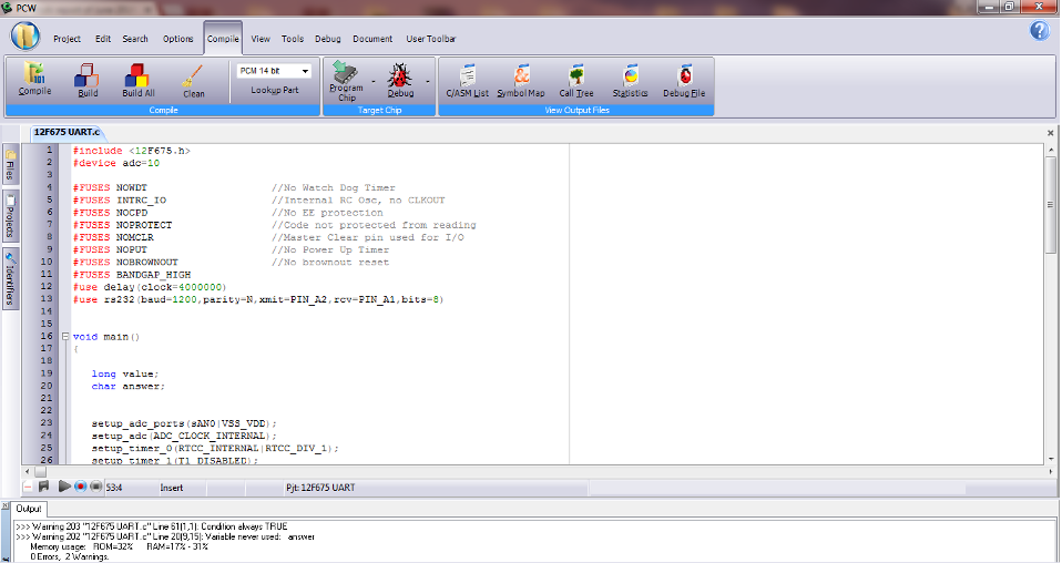
I developed the software using PICC Compiler..
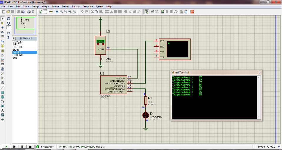
I tried simulatig the circuit using Proteus, here is a screenshot for the same..
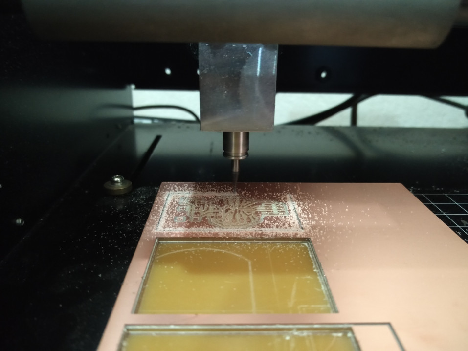
milling the PCB using modella..
milling completed and the edges being cut..
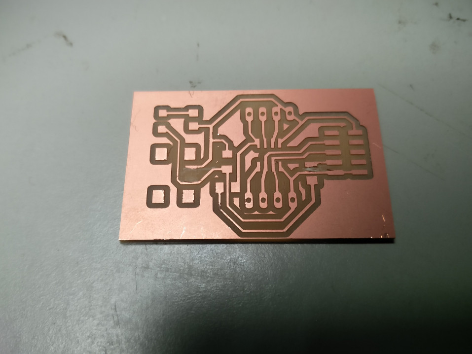
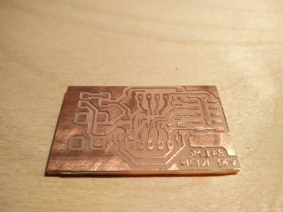
The completed PCB, you can see that I had to manually remove the shorting of tracks I found while verification on two places..
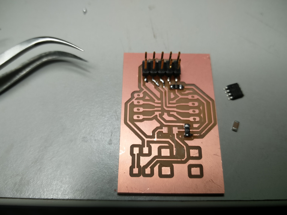
Stuffing the components..
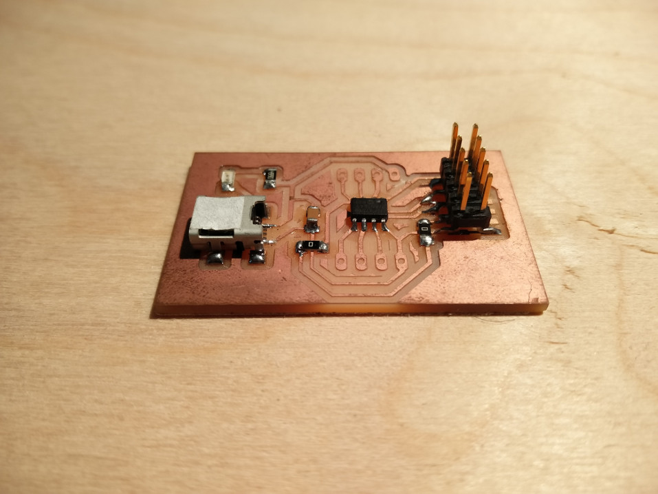
The completed PCB
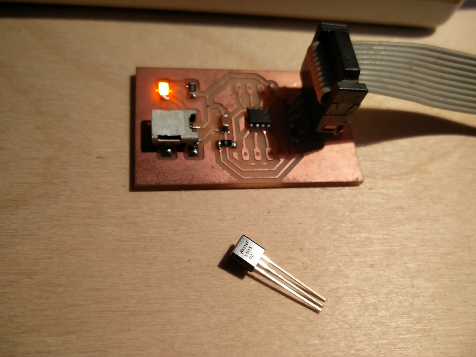
Connecting the board with the programmer, well to my good fortune I didnt had any trouble and the board got detected without any problem , I dumped the already developed code without much delay..
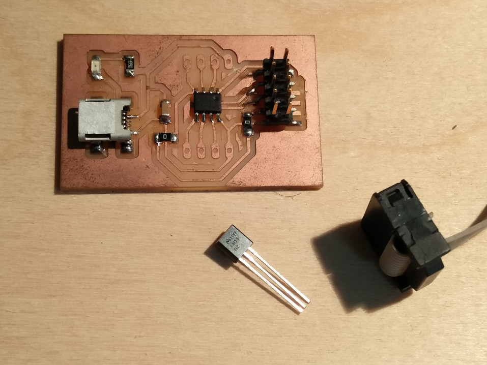
LM35, The sensor to be connected to the board..
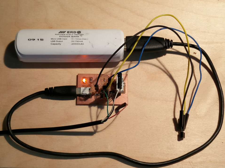
I soldered header pins to connect the sensor and USB to TTL cable..
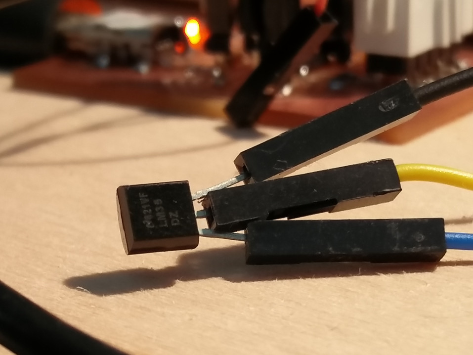
A closer look..
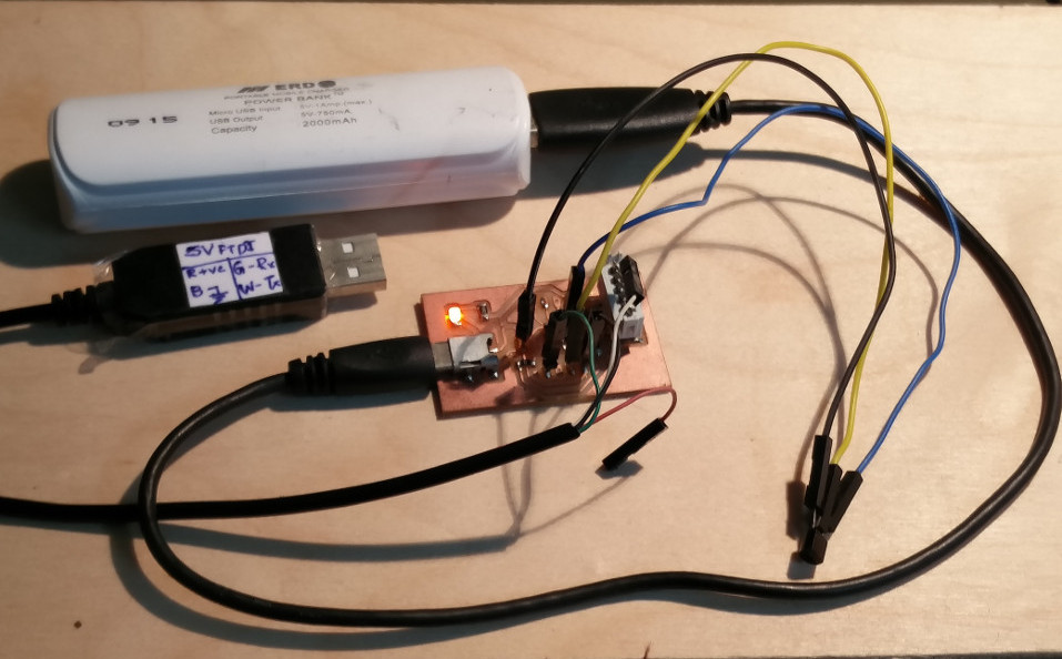
You can find that the board is given provision to be powered externally to avoid overloading USB. Here is the complete hardware used for the process..
FINAL SENSOR READING
Here is how it I received the serial data from the microcontroller after processing..I used the Terminal Program to read from the serial port.
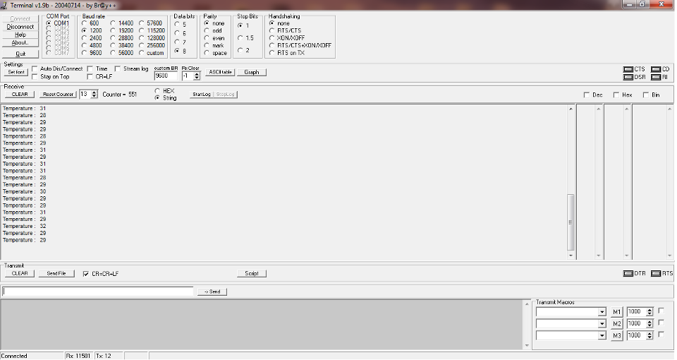
This does make me think of making my own terminal progrm as I will be extensively using serial interface in my final project, food for thought for my interface assignment week :)
Here is another version of the SM_FAB PIC12F Pcb with the errors corrected, this is included with the design files..
The design files can be downloaded from here.
Bouncing & Debouncing of Switches
Bouncing is the tendency of any two metal contacts in an electronic device to generate multiple signals as the contacts close or open; debouncing is any kind of hardware device or software that ensures that only a single signal will be acted upon for a single opening or closing of a contact.
For better understanding, When you press a key on your computer keyboard , you expect a single contact to be recorded by your computer. In fact, however, there is an initial contact, a slight bounce or lightening up of the contact, then another contact as the bounce ends, yet another bounce back, and so forth. A similar effect takes place when a switch made using a metal contact is opened. The usual solution is a debouncing device or software that ensures that only one digital signal can be registered within the space of a given time (usually milliseconds).
Fortunatly as I am not using any mechanical inputs for this week, I didnt had to deal with this effect, but this is some thing to be takencare of while desiging circuits with even simple pushbutton switches.
Here is a link to a very detailed tutorial on this.