EMBEDDED PROGRMMING
This week is specially meant for one of my most favourite topic, embedded programming :) Ill be updating with as much as embedded architectures I can experiment and learn.
If time permits I'll also play around and document the following, I have got all of them ready in hand for this weeks Fab learning,
And something very special to me,
1. FIRST PREFERENCE TO THE FAB STORIES!!..
My EXPERIMENTS WITH - Atmel ATTINY 44
I have already made FTDI hello world module during MY PRE FAB , So I am not repeating the same here. The learning experiane I had is documented as such for reference. The first process I did was downloading few examples from the archive and start experimenting with it using the Kokopelli CAD tool to make my own board, the process I followed are as follows..
KOKOPELLI
kokopelli is an open-source tool for computer-aided design and manufacturing (CAD/CAM).It uses Pethon as a hardware description language for solid models. A set of core libraries define common shapes and transforms, but users are free to extend their designs with their own definitions.
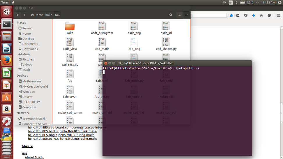
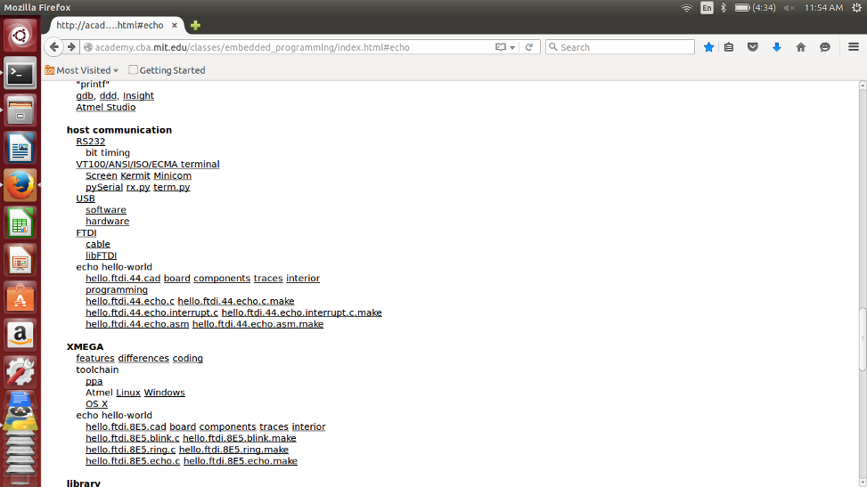
Franscisco introduced us Kokopelli. We started playing aroung it by downloading the FTDI hello world examples shown in the following screen..
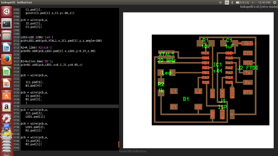
We added a button and LED the exiting board and learned how to tinker with kokopelli
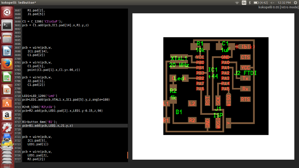
In kokopelli we never draw a circuit, instead we write codes for that as shown below. The graphical reasult is shown to the right.
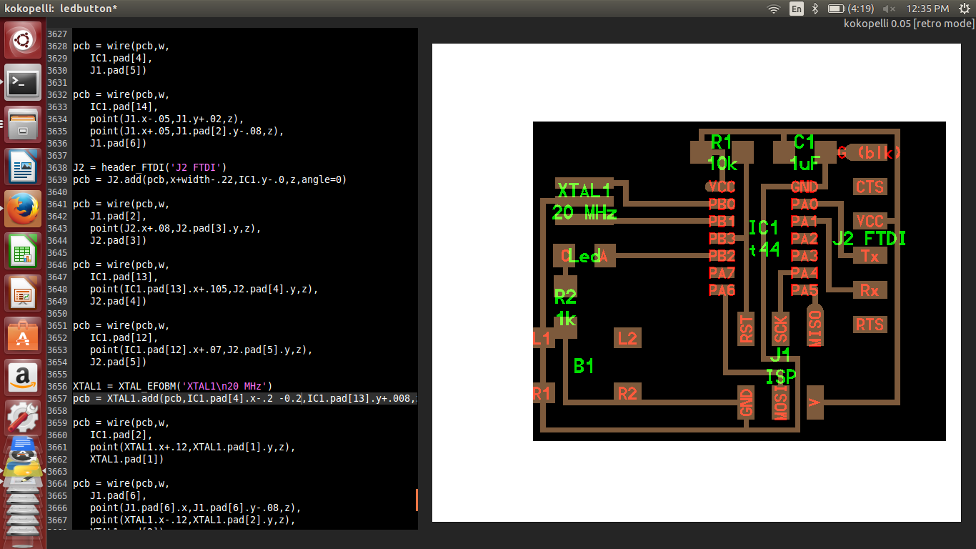
Once the initial starting trouble was overcome, playing around kokopeilli was fairly straight forward and easy to understand. We should understand how each component is added as classes and how to place them in the borad refereing to another component already exixting in the board.
I completed the board with out much difficulty and it is ready to be exported for miling, while exporting we can mention the resolution of pixels. Initially I gave 10, but it was not sufficient and then I repeated the same with a resolution setting of 40.

Inorder to export the traces and board outline seperately, we have to comment or uncomment the desired output settings available in the initial part of the code as shown below.

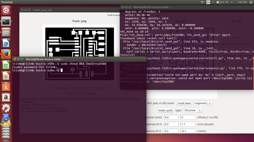
The image files are ready to be milled and the screen shots of the same are attached for reference. I am not givng a detailed description about how to mill PCBs as it is already explained in the Modella PCB Milling section.
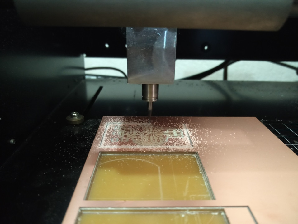
Milling the traces..

Cutting the board edges..

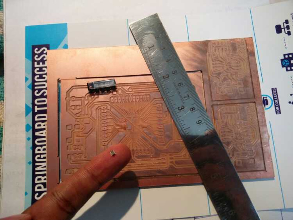
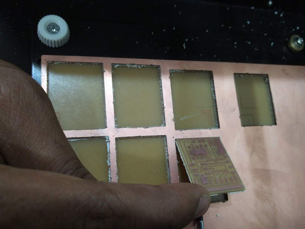
The completed PCB.
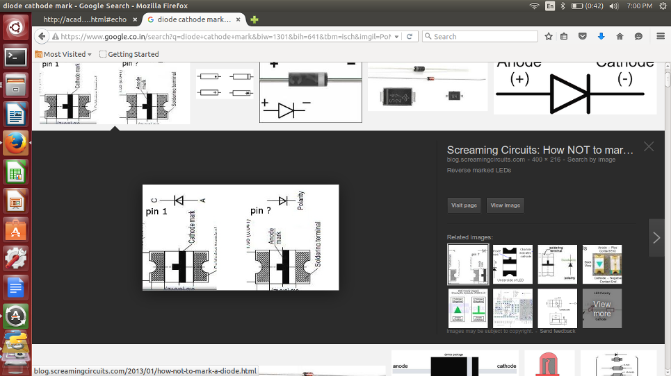
Now it is time to assemple the PCB, I had some confusion while trying to find the Anode and Cathode of the SMD LED, The following diagrams are for reference.
The completly assembled PCB.

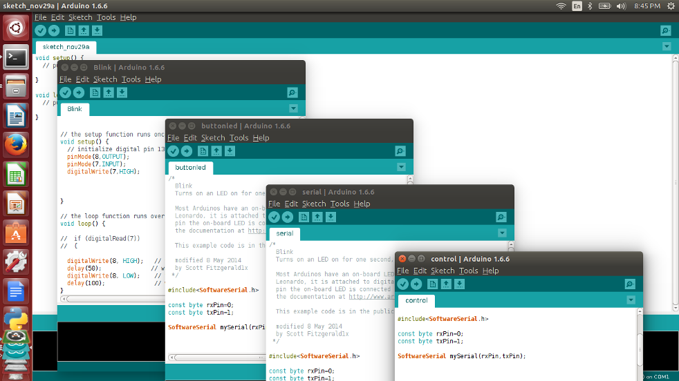
These are screenshots of few programs I tried..
All the design files used for the programming can be downloaded from here
MOVING ON TO OTHER ARCHITECTURES
Microchip PIC 12F675
PIC12F675 is a powerful (200 nanosecond instruction execution) yet easy-to-program CMOS Flash-based 8-bit microcontroller.This Microchip’s powerful PIC MCU architecture is packed into an 8-pin package and features 4 channels for the10-bit Analog-to-Digital (A/D) converter, 1 channel comparator and 128 bytes of EEPROM data memory. This device is easily adapted for automotive, industrial, appliances and consumer entry-level product applications that require field re-programmability.
Most important features of it are,
This is just a summary of its features going through its data sheet, you can reach the same from here to know more about it..
SM_FAB PIC12F IN THE MAKING
I started by making my custom PCB keeping in mind to make a generic development board so that I can use it for different purposes.
Main features I wanted this Board to have are,
Here is how it evolved. I am not going to explain every step of PCB fabrication in detail as this weeks learning assignemnt is to concentrate using as many Microcontrollers, IDEs and platforms as possible..
milling the PCB using modella.
milling completed and the edges being cut.
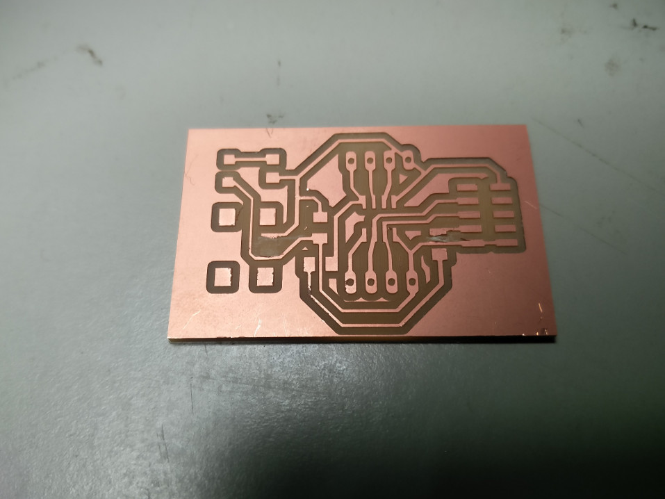
The completed PCB, you can see that I had to manually remove the shorting of tracks I found while verification on two places..
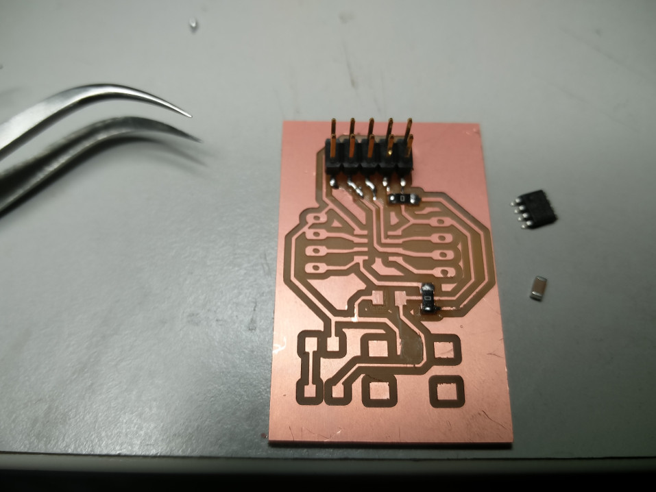
Stuffing the components.
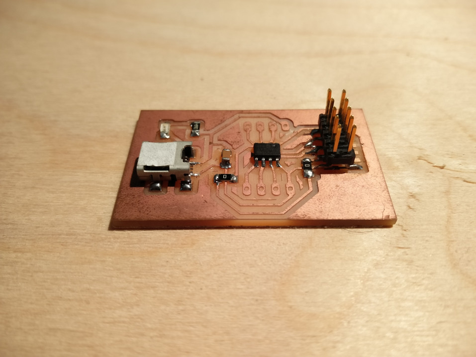
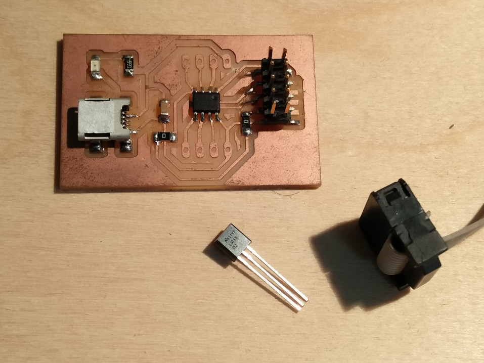
The completed PCB
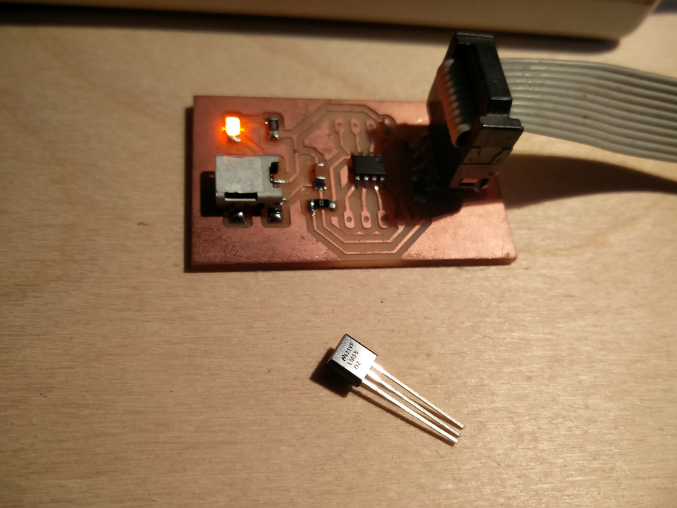
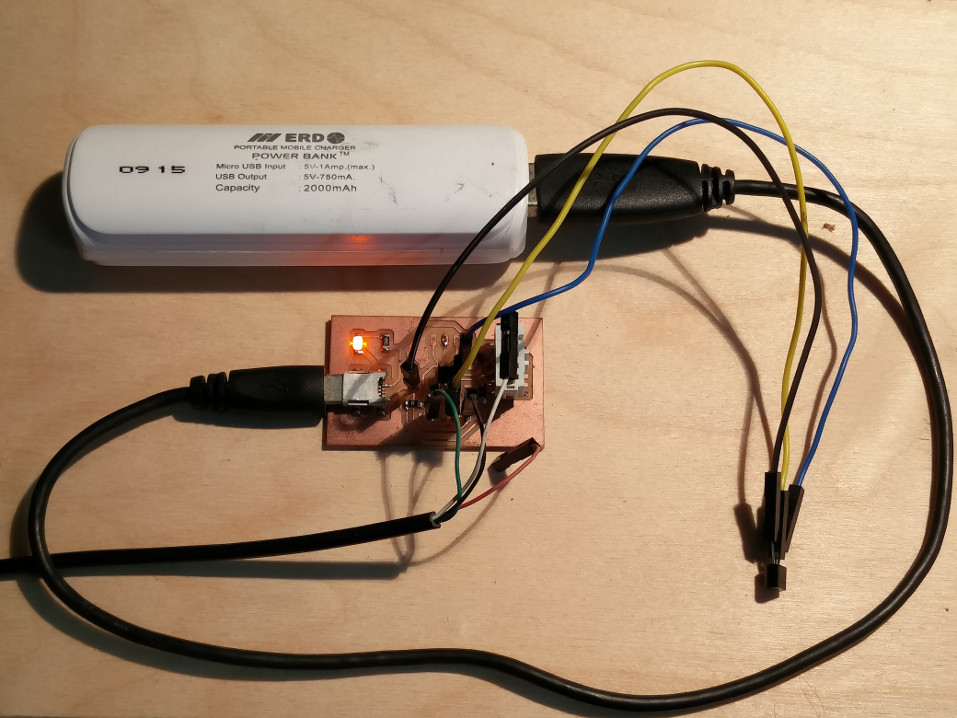
Connecting the board with the programmer, well to my good fortune I didnt had any trouble and the board got detected without any problem.
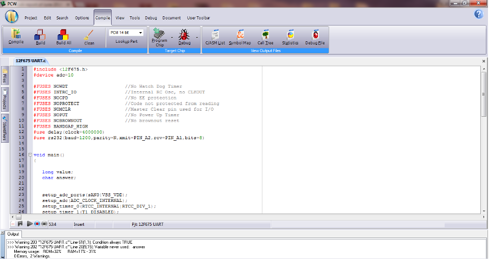
EXAMPLE-1 PROGRAM - USING ADC using PICC COMPILER
This is to demonstrate programming the microcontroller to read LM35 temperature sensor.
I developed the software using PICC Compiler.
I also tried simulatig the circuit using Proteus, here is a screenshot for the same.
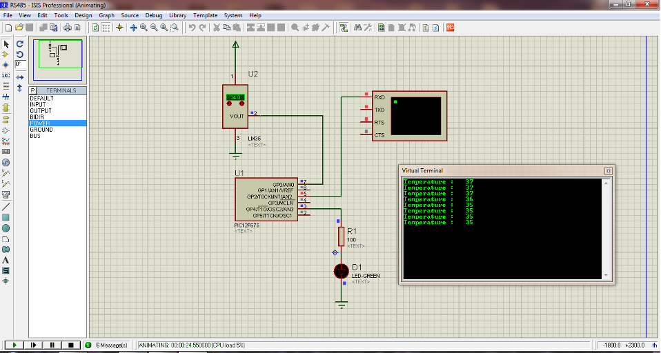
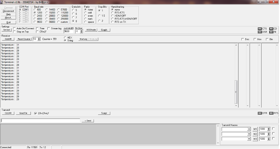
FINAL SENSOR READING
Here is how it I received the serial data from the microcontroller after processing.I used the Terminal Program to read from the serial port.
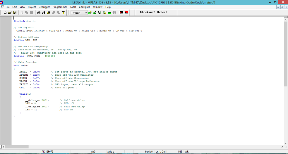
EXAMPLE-2 PROGRAMMING USING MP LAB IDE
This is another example program for the PIC12F675 using MP LAP IDE.This is just a simple LED Binking Program for demonstration of this IDE.
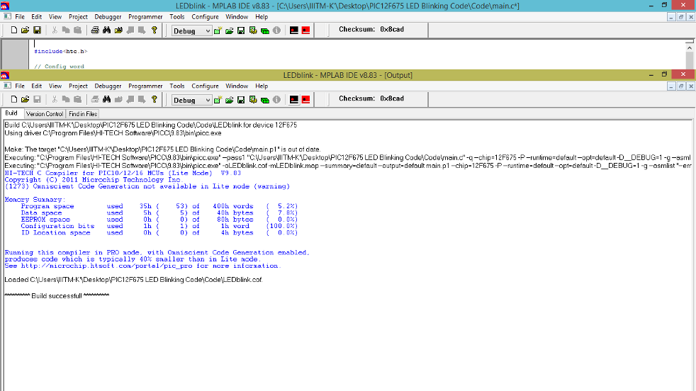
Building the program..
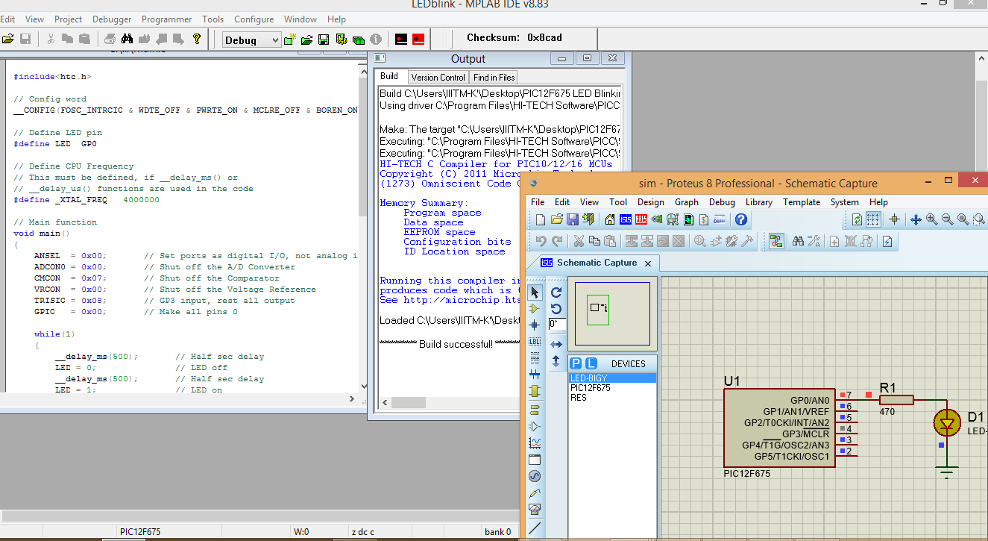
Simulating the program using proteus.
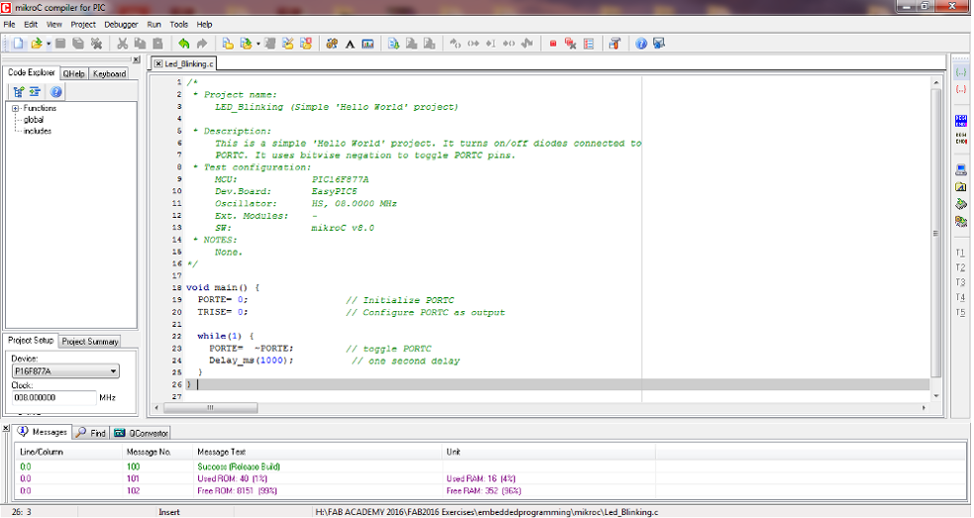
EXAMPLE-3 PROGRAMMING PIC16F677A USING MIKROC IDE
Before we dive deeper into the programming aspects, let me introduce my SM_FAB PIC16F Board designed for generic purpose, mainly thniking of the final project.
Main features I wanted this Board to have are,
I am not going to explain every step of PCB fabrication in detail as this weeks learning assignemnt is to concentrate using as many Microcontrollers, IDEs and platforms as possible.Detailed explanation of making this board will be documented in my Output Week Assignment documentation page.
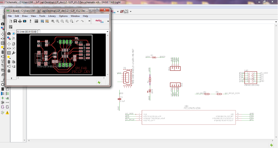
CIRCUIT & PCB DESIGN - USING EAGLE
Schematic Design and PCB was developed using EAGLE CAD, The following shows screenshots shows the various stages of development.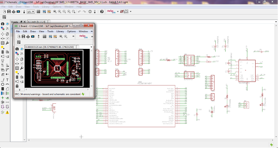
MODELLA - PCB MILLING
The finished milled PCB, ready to be cut and removed,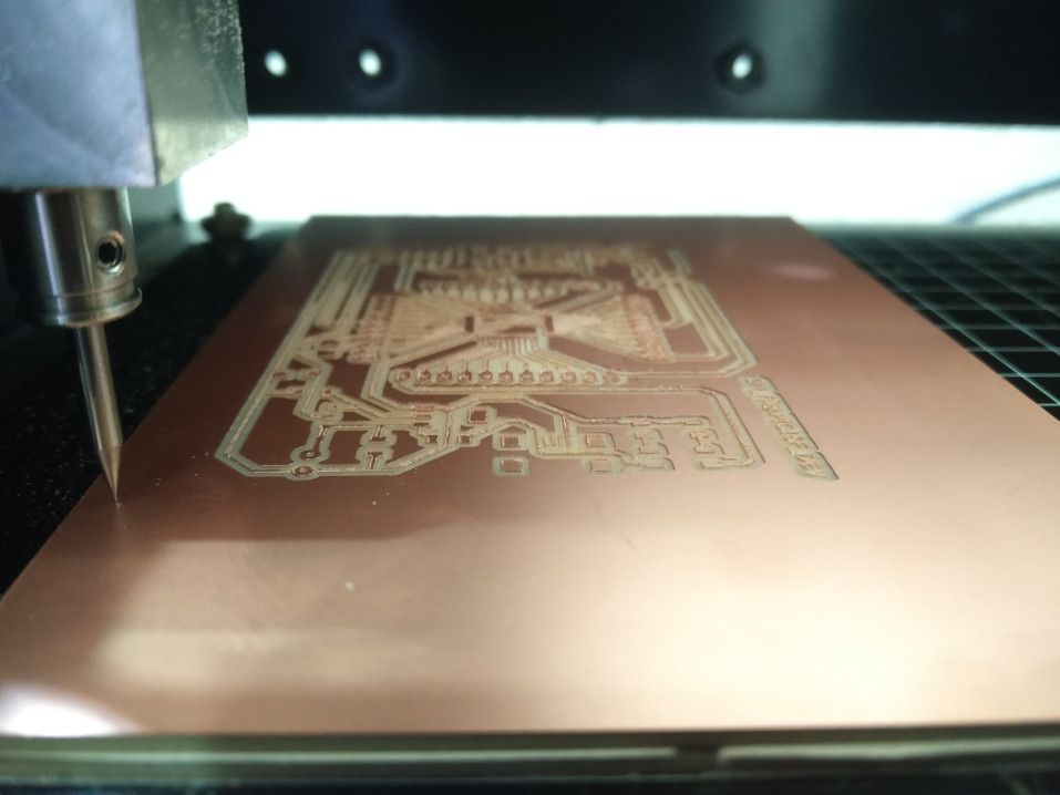
Adapter PCB with the microcontroller soldered to it, ready to be fixed to the motherboard.
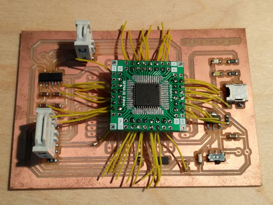
Though I felt it simple, it wasnt that easy to solder all the wires. it took a while for me to get them soldered. Well no giving up!!
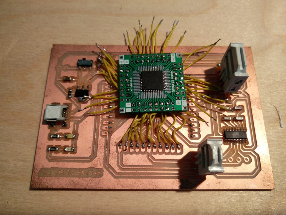
It was time to check one of the critical things, the ICSP connectivity. well to my goodfortune that worked the very first time I plugged in, My programmer could detect the PIC16F877A.. finally a great relief to the hectic soldering :)
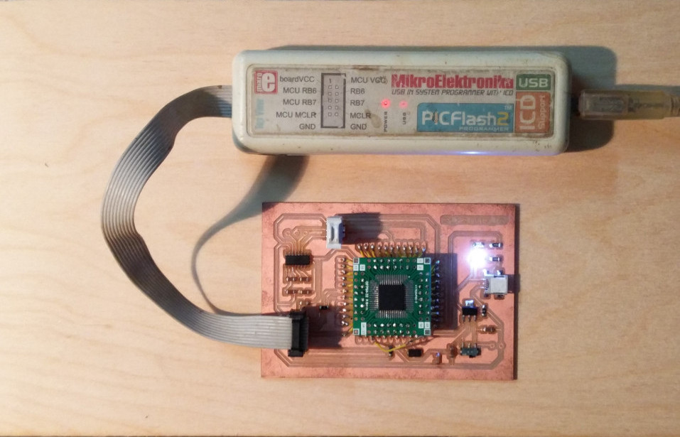
MIKRO C Example proram.
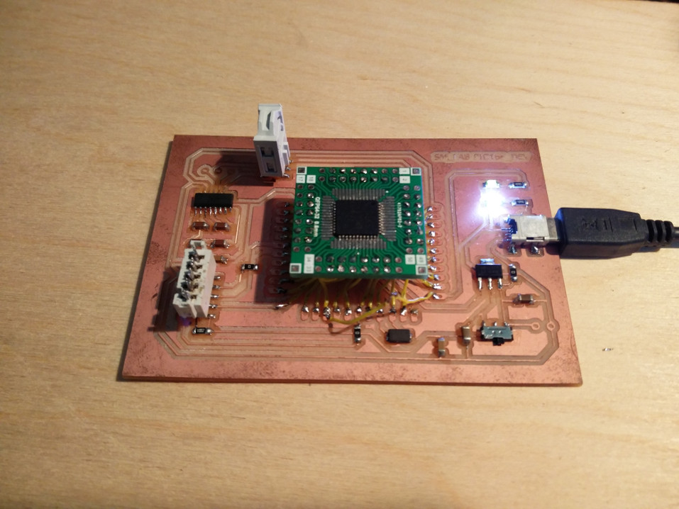
The LED next to the Power LED is the test LED on PORTE, I have now powered on the board using external USB connector as you can see..
All the design files used for the programming can be downloaded from here
As mentioned in the begining,
These boards will be documented later as time permits..
Well, but before I close this page, let me show you the PIC10F I was talking about experimenting in the begining, once I finish designing its PCB, Ill update it here :-)