Week 13 - Output Devices
Add output devices to a microcontroller board and program it
Steps:
* Mill a board with Fab Modules
* Create the board with a laser print
* Create the board with a laser cut machine
* Assemble it and program it
Mill a board with Fab Modules
I milled many PCBs for the Academy and in this assignment I decided to try new PCB creation techniques. For these tests,
I chose to use the example of the LED array.
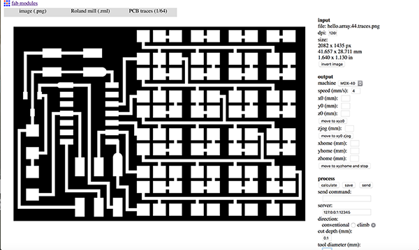
I started with the Fab Modules:
very simple approach, it was enough to go to Fab Modules , load the .png image and follow the steps, selecting the
machine to use, the operation to be performed and controlling the parameters which gradually appeared to me.
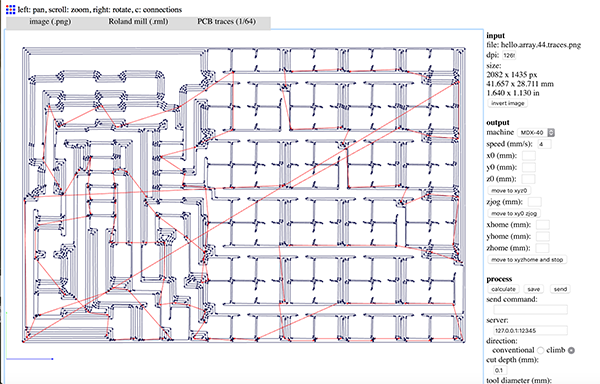
I have not yet figured out why, but instead save the file directly in the download folder, when I click the save button,
it open a page with Gcode. I saved the content of the page in a text edit and I saved adding the .nc
extension to the bottom.
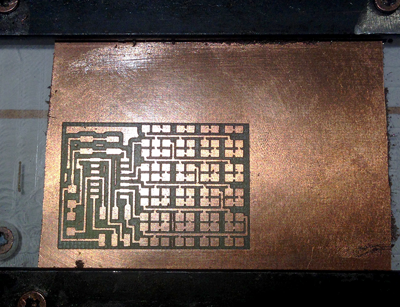
Than I open it in our Modela MDX-40 and I milled.
Create the board with a laser print
I know, I should not, but I'm doing it in the name of science and I promise I will manage that little ferric acid with care
and I'll take the necessary precautions for disposal: I'm too curious.
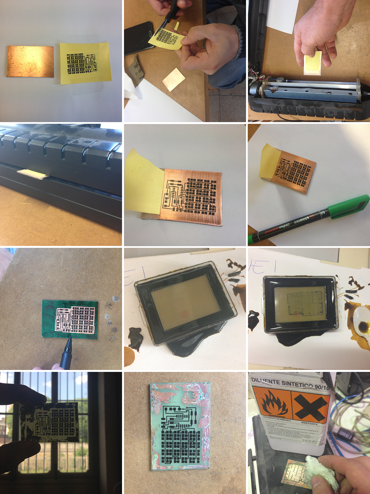
First I took the immagnie .png and I reversed the
white with blacks with a vector program (Illustrator in my case). Then I mirror the image and I have prepared a file ready
to be printed by following the instructions in this tutorial
and I integrating it with the suggestions of some members of the FabLab. I need a Laser printer to print my .png over a special glossy
sheet and than pass it trough a laminator. I found everything at FabLab except the glossy sheet. I ask it to a friend of mine.
While I was waiting for it, I test some different kind of paper taken from newspaper an magazines.
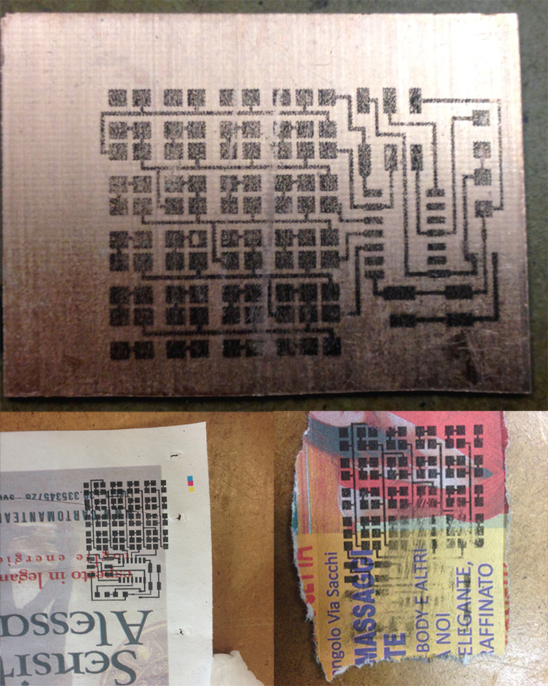
Failed tests. Fortunately, then came the glossy foil. So I printed, I paired the sheet with the copper base (sand it before a little it), I steak it just from one side, and I hot rolled all together several times. Than with a marker I correct the route and I paint all around the board to optimize the operation. I dipped in ferric chloride and I wait the right moment to pick it out. Wash it, and take away the ink.
Create the board with a laser cut machine
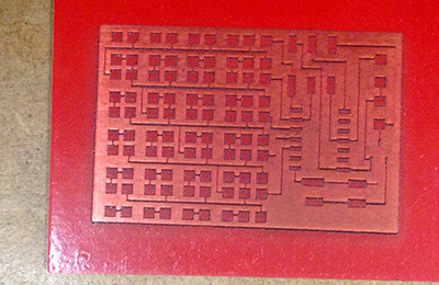
I knew that with the fiber laser machines can scratch away the copper. Unfortunately we have a CO2 here. Since we were in the
test zone, with Stefano Paradiso we painted a copper base with two coats of vernicie, we let it dry overnight and then we did an
engrave to remove paint and get the pcb ready for the ferric chloride.
I use a jpeg of the same project. Engrave: power 25,
speed 400, gap 0,05mm.
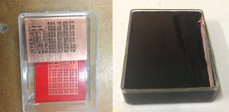
I have collected all the other tests and I dipped in ferric chloride in the same plastic container (also glass would be fine, not use a metal container!). I waited all night long, then I pick them out and I cleaned. I have not found a way to neutralize the ferric chloride, so I put it in a container that I will bring in landfills for proper disposal. NOT RELEASE INTO THE ENVIRONMENT, naither in the sink or in the toilet.
Assemble it and program it
I soldered all the components and I programmed according to the instructions.
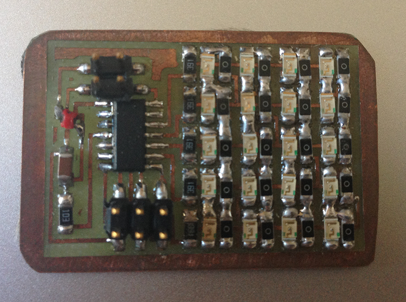
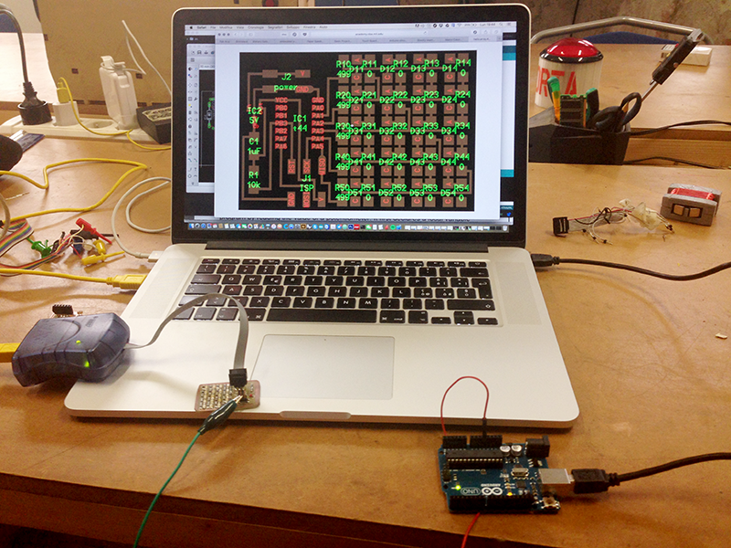
I use a commercial avrispmkii to programm it and an ArduinoUNO for the 5V.
My array doesn't works well,
I found some solders that make contact, as soon as I have time I put it in place, Charlieplexing
is a very interesting concept and I am fascinated by this solution.
I simply use the exercise code because in this week I spend a lot of time testing. anyway I use a custom output in my final project.
RETURN UP
| ← week 12 / Molding and Casting | week 14 / Composites → |
|---|