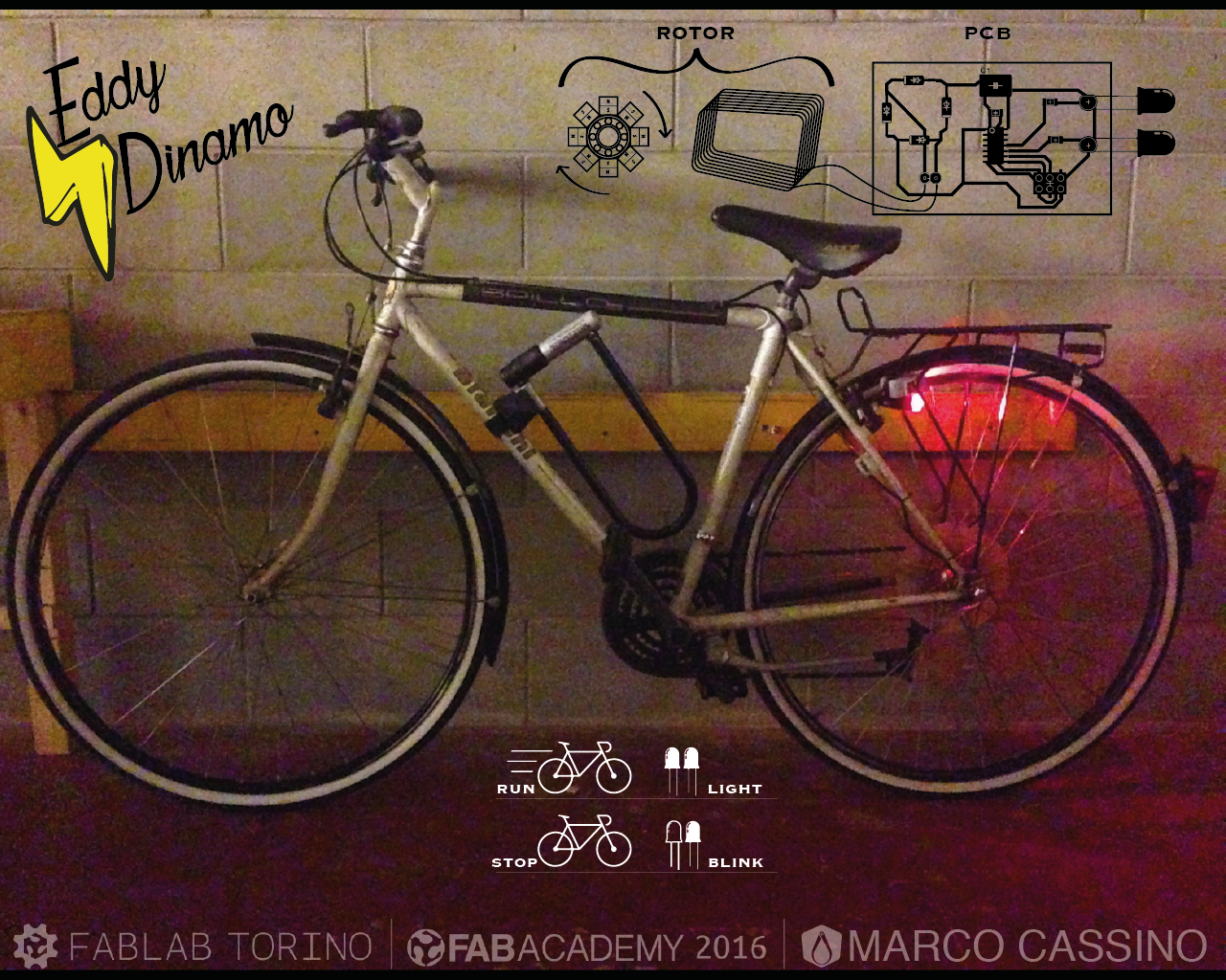
For years, I'm passionate about energy harvesting. I suffer to see it wasted and I admire the great discoveries in electromagnetism happened the second half of 800. For these reasons I have decided to create a lighting system for bicycles, because use a battery to illuminate a light of a moving object irritates me a lot.
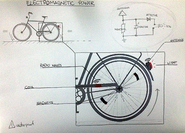
This light system turn on the leds while the wheel spins: with a rechargeable battery I hope that will stay turned on for a moment,
in order to be visibile also when you stop. I'ts contactless so here is quite no friction. It uses magnetic induction and
should be wire, battery and maintenance free and waterproof of course!
There are a lot of DIY versions of this kind
of safety lights, and some of those were very inspiring for me. I want to upgrade the project
also with the radio waves system in order to transform the bike’s moviments in energy, ready for oder project like alarms,
lights, power banks, gps locator...
The solution with the radio waves could be risky, although I would love to. I reserve
the possibility of using cables to transport the energy produced.
I recently discovered the potential of the
eddy currents that could simplify my project, reducing components and
settings and take over the wire without radio wave technology.
Steps:
* Eddy current
* Electromagnetic induction
It may seems strange, but you should try: take an aluminium tube and let fall a magnet into it. You'll be sourprise like a child.
If you don't have these items and you can not try the experiment, you can take a look at this video.
 Image by Chetvorno - Own work, CC0
Is the production of an electromotive force or voltage across an electrical conductor due to its dynamic interaction with a magnetic field. It's a very interesting argument and could take a lot of time. I suggest to have a look at this video to make you excite following this topic. Thanks to Walter Lewin with his amazing Youtube channel "Lectures by Walter Lewin. They will make you ♥ Physics" give to the world a big oportunity to learn physics.

Steps:
* Magnets rotor
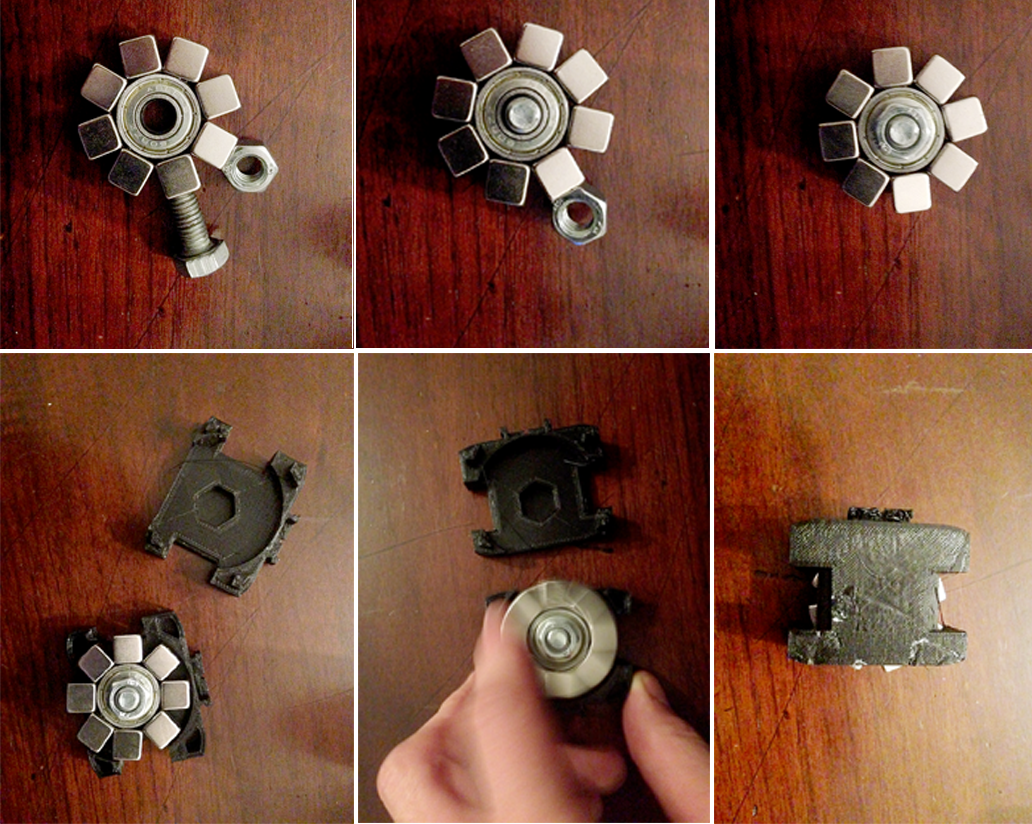
* Design a case
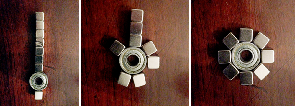
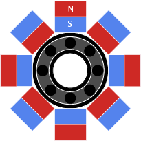
First I took a classic 608 ZZ ball bearing, easy to find and cheap as it is the skateboards' standard measure. It is perfect because it is ferromagnetic and runs well. Then I took 8 cubic extremely strong neodymium magnets with 10mm side and I placed them on the outer ring, alternating polarity (you will be forced by the magnetic attraction exerted to position them like that).
I use a sort of "desk bike" to test if the rotor works.
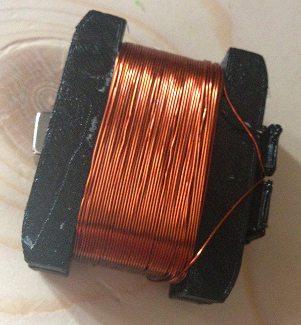
I have designed a structure to hold the ball bearing with the magnets and give the possibility to wrap around the copper wire to create the a solenoid. It is very important that the magnets enter and leave by the solenoid to generate current.
Struttura Rotore by marcocassino on Sketchfab
I assemble all and I wrap 10m of copper wire Ø 0.4mm.
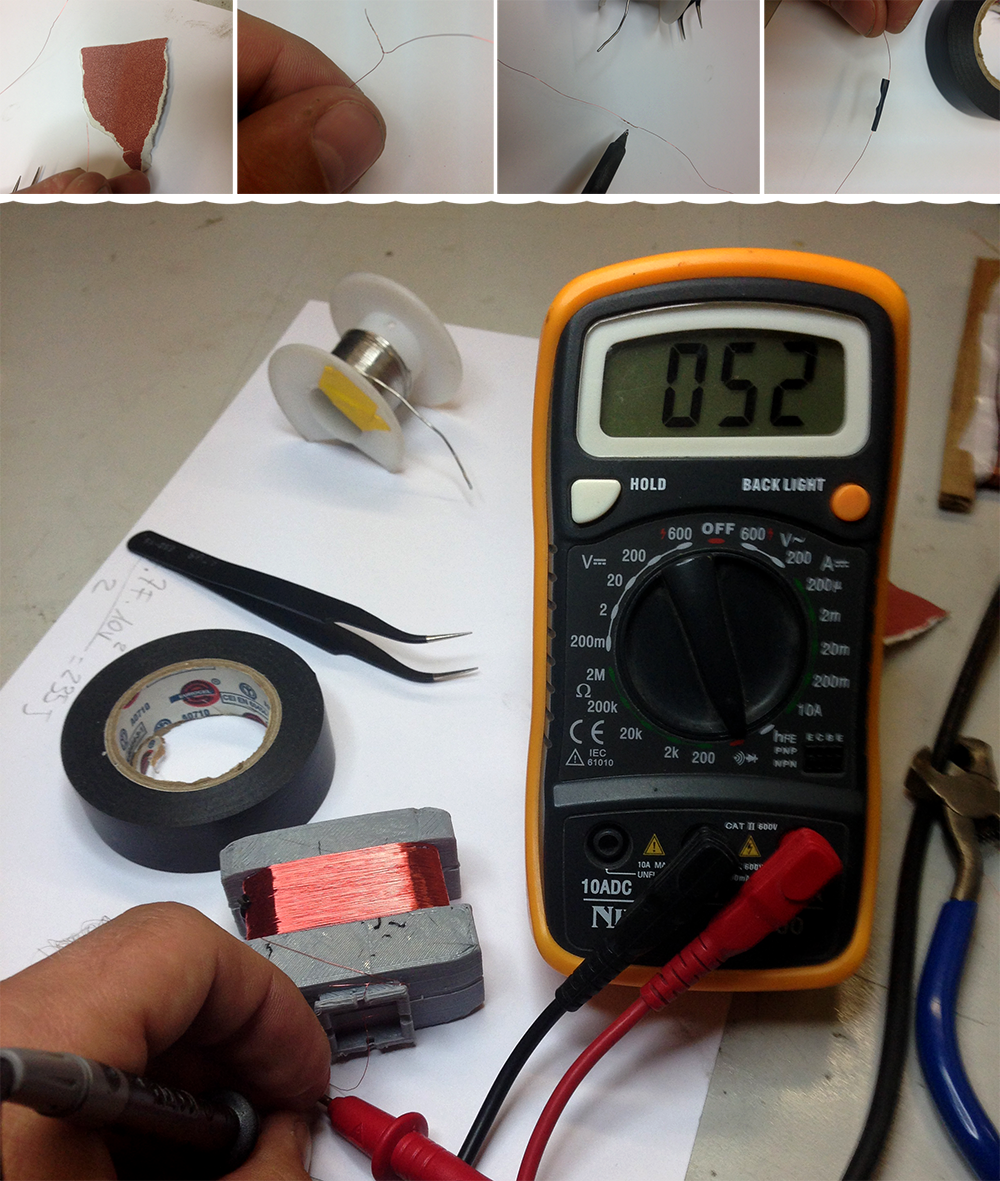
The first tests with the copper wire Ø 0.4mm I bought were pretty disastrous, so I decided to use a wire Ø 0.2mm that
I have recovered from an electric motor. Unrolling the wire from his location I had to cut the wire in two places: as well
to increase the number of turns I decided to join them.
So I sanded the ends to remove the protective film, I twisted them,
I sealed with a bit of tin and then I isolated with tape. Beep Test: ok!
Steps:
* Electronic design
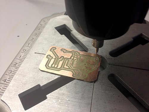
* PCB
I tested the generated electricity. I do not know what kind of energy I generated, so I started from the beginning: I connected my rotor to the oscilloscope and I tried to see what kind of wave I would generate.
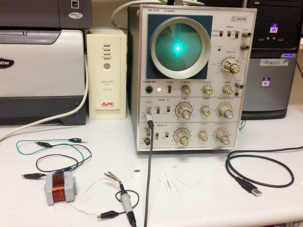
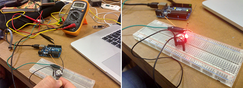
But it did not work because it is a bit old. So I tried by spinning the rotor and connecting it on the breadboard with a diode bridge and a capacitor, in order to stabilize the energy produced and try to figure out how much energy is able to produce my rotor to draw consequently an efficient PCB.
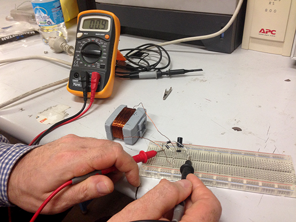
Unfortunately it was a failure, too little energy: I used a copper wire with a large diameter, should I try to shrink the
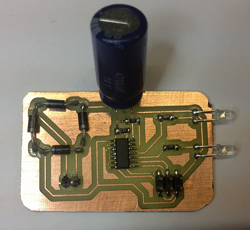
thickness to have a better result. However I have designed a PCB traveling with fantasy and assuming that my rotor works.
So I put my diode bridge that will charge a capacitor (super cap) of 4.7F, kindly borrowed by Officine Arduino.
In this way I should be able to collect enough energy to power an AtTiny84 that will make me blink LEDs when the bike stops, and I
can save energy and be more visible for about a minute when I stopped.
I spent a lot of time choosing the right kind of
input to use to determine when the LEDs should blink. Gyroscope, hall, tilt sensor, then the simplest solution is always the best:
I will connect a microcontroller pin to read the input voltage.
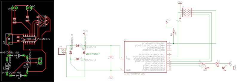
Here I explain how and why I created the diode bridge, that is used for conversion of an alternating current (AC) input into a direct current (DC) output.
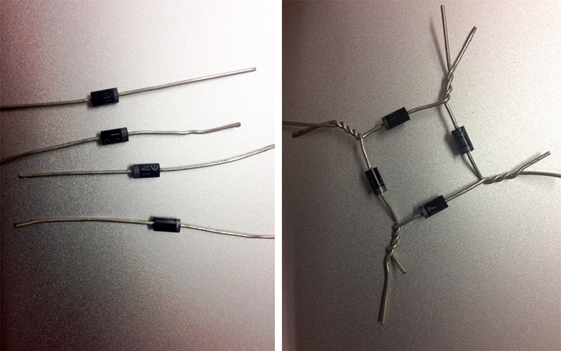
Image by Собственная работа на базе файлов из Диодный_мост
Here the Eagle file.
To storage the energy I will need a super capacitor ≥ 1F. I also need very efficient leds: the most efficient LEDs
currently available to get maximal light from minimal energy is CREE XPG G2 or CREE XM-L T6.
Could be a very good solution, but I should buy it from China but I don't have so much time. For this prototype I'll use hight
efficient 3mm leds.
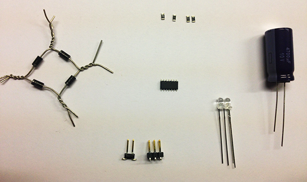
BOM
1 X super capacitor 1F 5.5V
2 X 3mm leds
MICRO ATTINY841
R1-R2 330 ohm
R3 10K
R4 0 ohm
D4-D7 DIODE 1N4007
1 X SMD male header 3X2 connector
1 X through hole male header 1X2 connector
I decided to usa an AtTiny841, but for this project you can use an Attiny44 as well.
To control when the leds start blinking, I connect the pin (ADC1) PA1 of my micro directly to the incoming energy route,
so I can know if I'm producing energy or not.
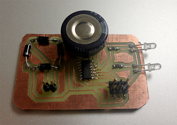
On the board I have used a couple of through hole components.
I calculate
my super cap's power by this easy function: 1/2·C·V^2 = (0,47F · 10V^2)/2 = 23,5J. I think 10V is too much, so I take
a 1F 5.5V one (1F · 5,5V^2)/2 = 15,125J: I'll test both and I'll decide.
I try with the breadboard my super cap and I found that has an autonomy of just over 10 seconds. So I tried the 1F 5.5V
one: about 30 seconds to reach full charge and takes more than 10 min to discharge powering one of the same LEDs I used for the PCB.
I did not expect a so good result!
That's why I decide to replace it.
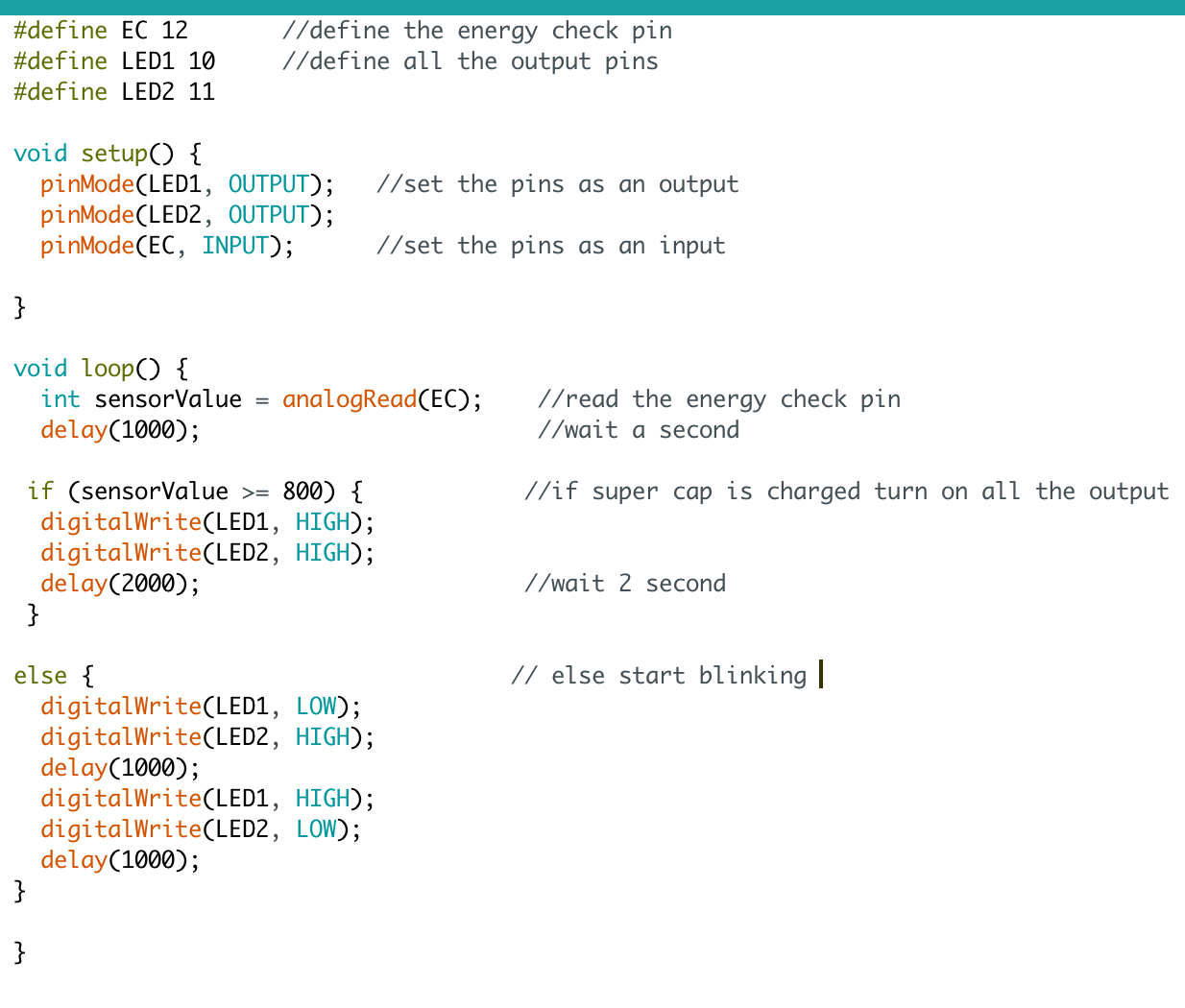
I programmed my micro with Arduino IDE. I write a simple code that check every 3 seconds: if enough energy → bright,
else → blink.
Remember: my project is under Creative Commons Attribution-NonCommercial-ShareAlike 4.0 International License. Feels free to replicate and improove it!
