
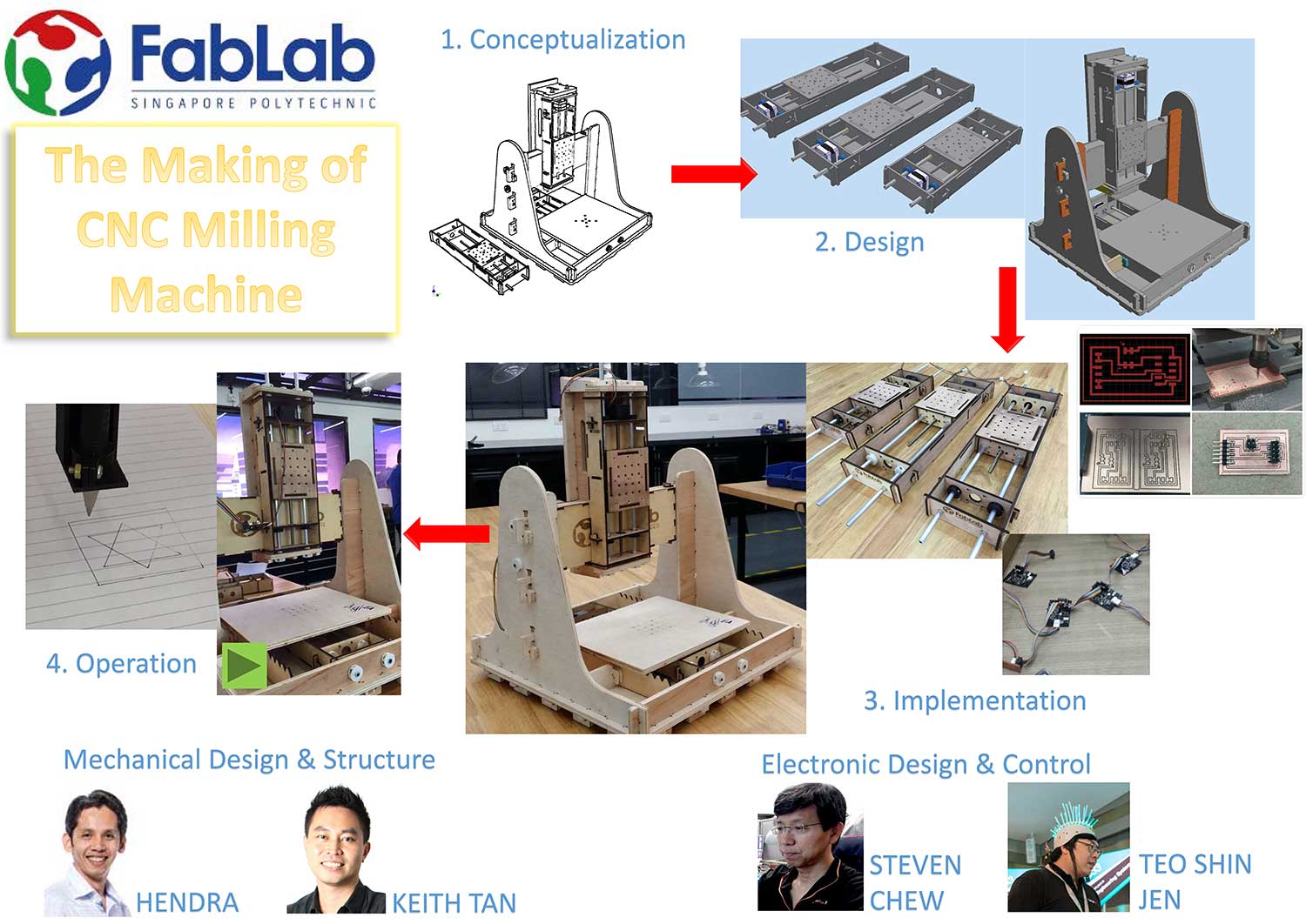
MTM Group 1
This section documents the implementation of our group's MTM project.
Questions/Tasks
Some of the questions that we asked ourselves and the tasks that we had to accomplish for our MTM project were:
- What machine should we build?
- The mechanical design of our machine:
- modular stages
- end effector(s)
- Automating the machine
- Milling & stuffing the interface board
- Testing the nodes & individual stages
- Programming the axes motion & end-effector(s) control
- Programming the user application
- Group and individual documentation for the project
What Machine?
After some discussion, our group decided on the following basic specifications:
- 2, 2.5D or 3-axis machine? Group decided to build a 3-axis machine
- End-effectors(s): possible end-effectors include:
- pen/marker
- spindle motor & end-mill or engraving bit
- 3D print nozzle
- syringe & pump mechanism
- low power laser
- Programming & automation
- building the interface board
- motion control of the 3-axis: pygestalt or mods?
- End-user application
- Creation of artwork: use vector software
- Conversion of svg/hpgl/png/gcode to pygestalt coordinates
- Desiging the application UI
- Documentation of the project
1) Design of Motion Stages
Refer to Hendra's site for more details.
Designing of the motion stages involves:
- Gathering of inventory
- Designing and producing drawings in Autodesk Inventor
- Machine Cutting
- Assemblage
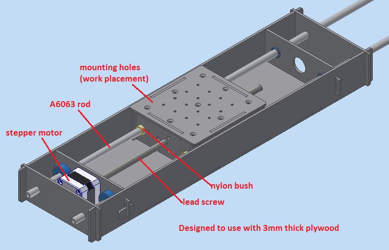
a) Inventory List:
-
Material:
- tri-fold cardboards and/or 3mm plywoods
- flanged nylon bushings (for tube with OD 3/8")
- 2fts A6063 hollow rods
- AQS Nema 17 stepper motor with in-built lead screw (4 starts-2mm pitch-OD8mm)
- Gestalt board
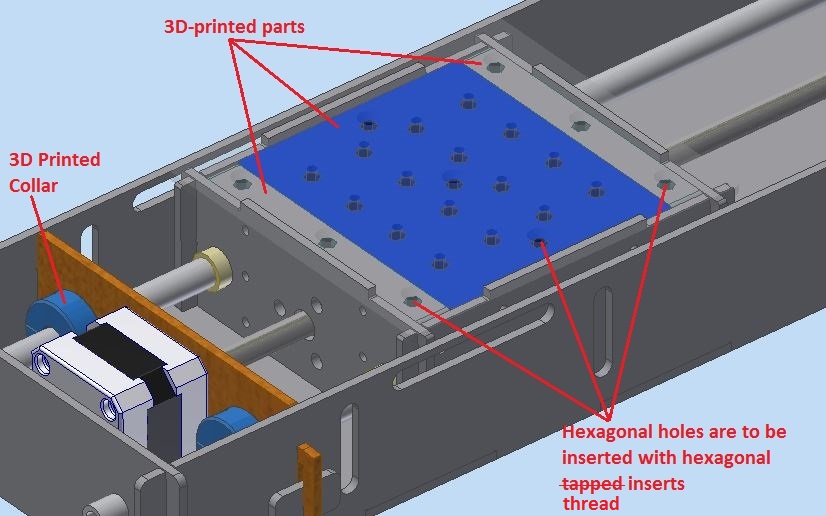
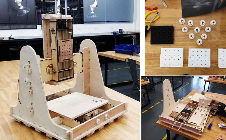
Design in inventor into modular and interchangable axes, the following show the X/Y/Z axis module.
Brass hexagonal thread inserts are used to reduce the wear and tear on the work placement plate (in this case, it is also made of plywood).
c) Machine Cutting
Plywood components fabricated using laser cutter.
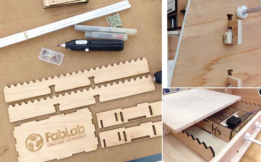
d) Assemblage
Final assemblage of fabricated parts.
2) Design of End Effector
Refer to Keith's site for more details.
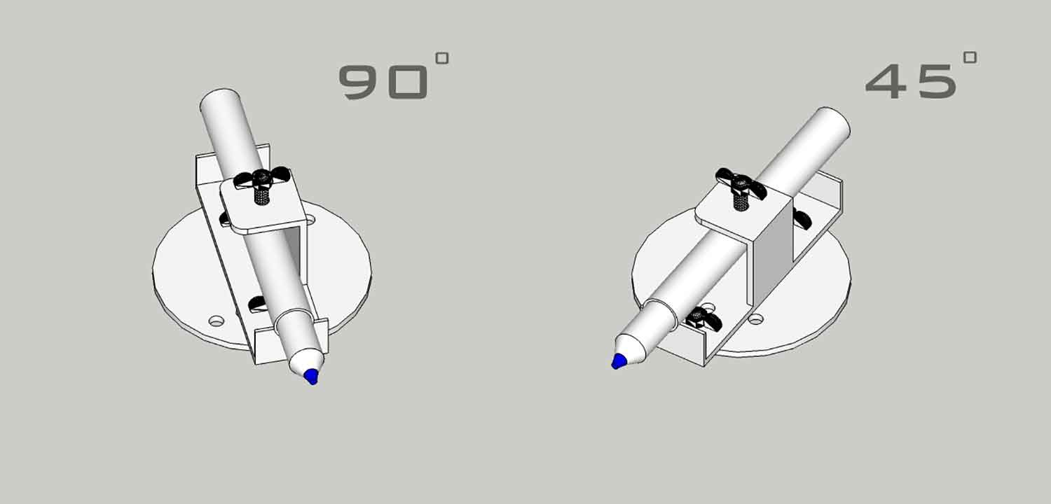
a) Design
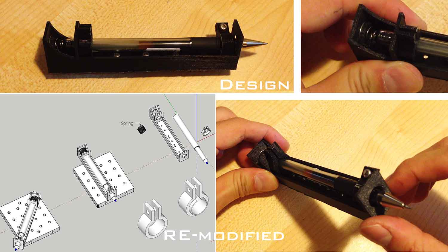
After discussions with the team, a simpler End Effector design was chosen, similar to the Axi Draw machine. The elements consists of a grip, capable of holding onto variant sizes of markers, pens and pencils, fastened using 4mm M4 Wing bolts. The grip shall be attached to a circular plate which is essentially connected to the 3-axis machine to allow for changing of inscribing angles.
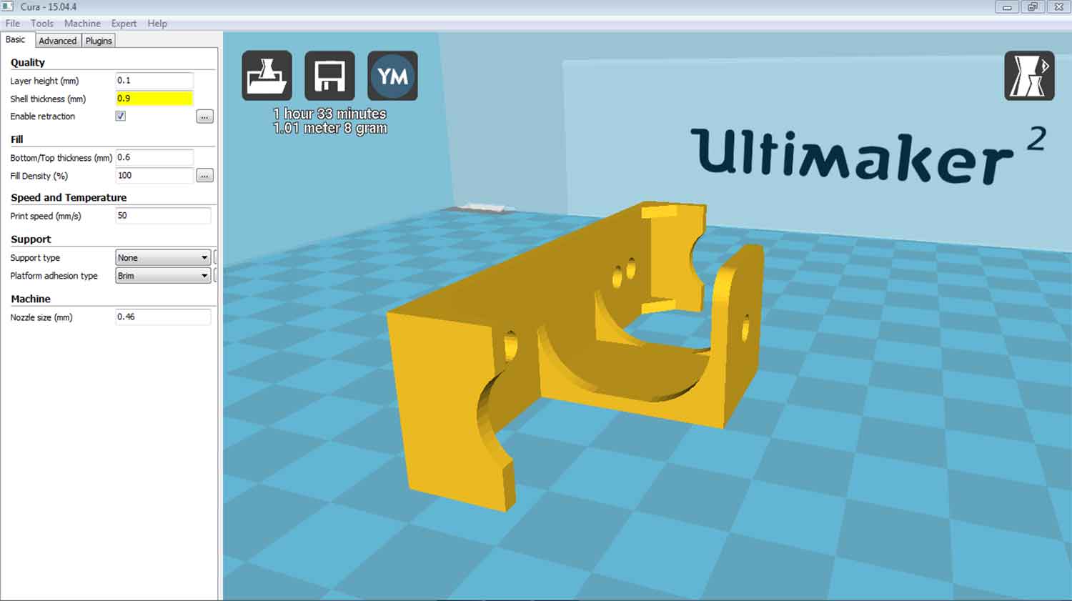
The model was created using sketchup and exported as stl format for printing. Creating the model was simple and straight forward as the design consists of simple geometries. Extra efforts were put in grouping the components as they needed to be saved as seperate stl files for 3D printing.
End Effector Sketchup file: Download
b) Print
Using Cura, the End Effector model was initially set to a default of 20% fill density. The printed model was further experimented with bending and pressing to test for possible breakage. It was broken quite easily. A second attempt was done but this time supports were added at all corners and overall thicknesses were increased to 2mm. The second attempt was also printed with 100% fill density and the print result was a lot more sturdy and firm. Fitting the various stationeries onto the End Effector was a breeze.
3) Programming & automation
Refer to Steven's & Shin's site for more details.
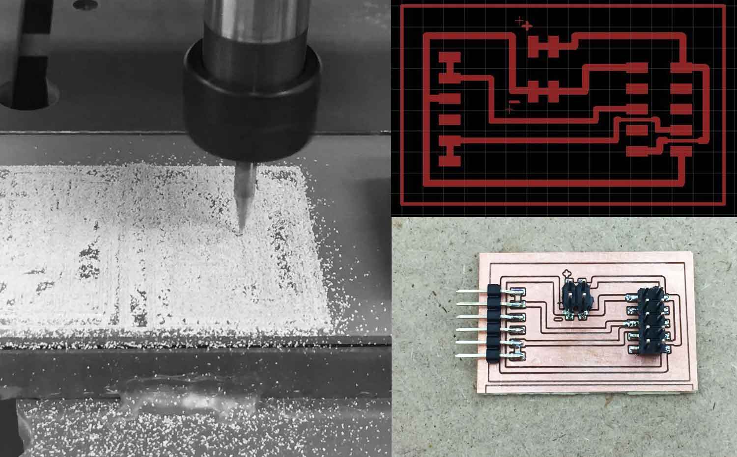
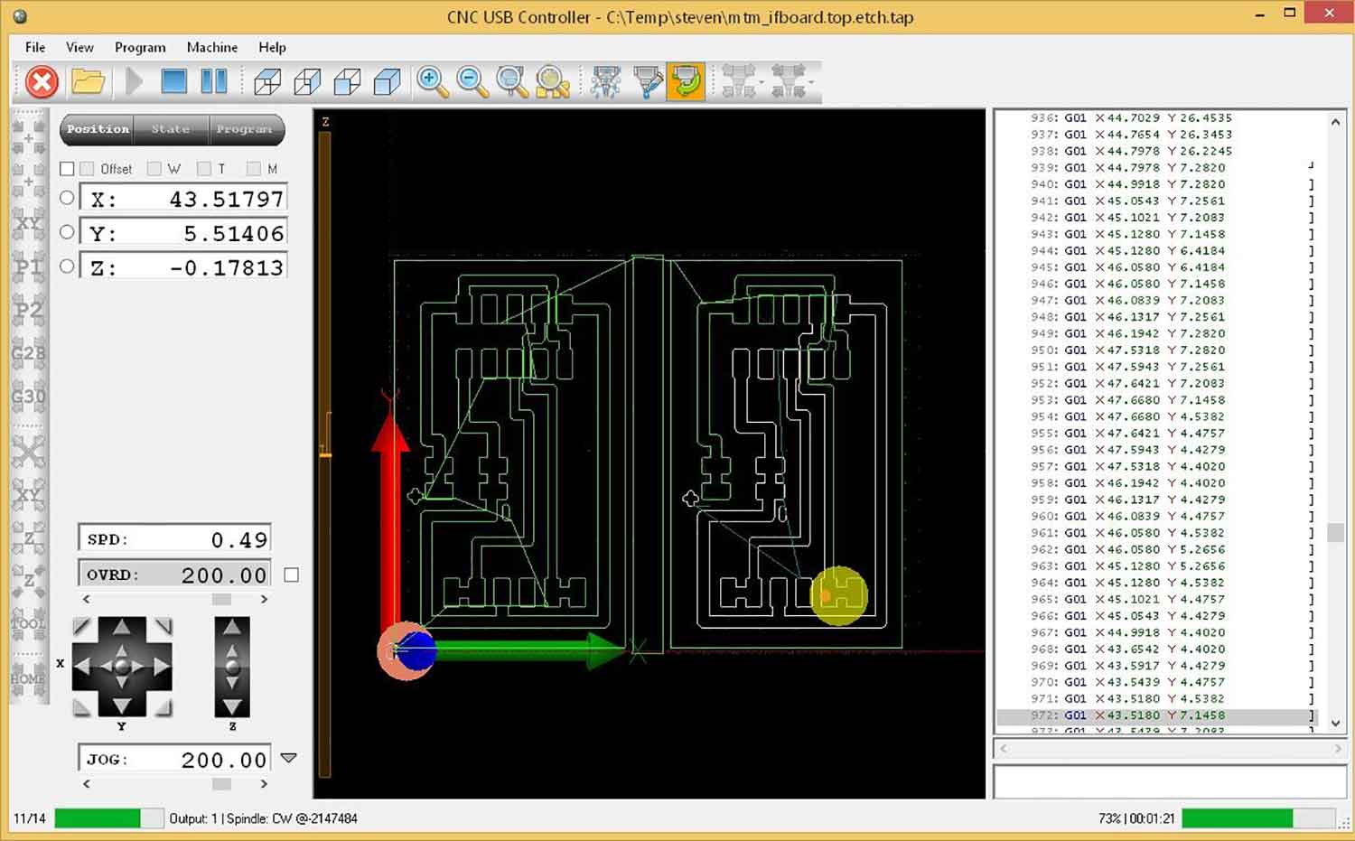
a) Making the interface board
Using the gestalt nodes for our machine, fabrication of the fabnet interface board was completed first for our gestalt nodes. The interface board was designed based on Bas' design, which allows us to use a 10-way IDC cable to connect to the Gestalt nodes.
b) Motion control of the 3-axis: pygestalt
The PyGestalt framework is based on the concept of a virtual machine. Within the virtual machine, the user defines:
- the interface for the machine (initInterfaces)
- the number of axis/nodes (initControllers)
- the coordinate system in use (initCoordinates)
- the characteristics of each axis such as number of microsteps, degrees per step, linear motion per revolution and direction
- public interfaces/functions: e.g. move(), jog()
- machine position
- spindle speed setting
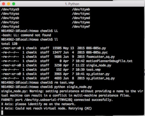
In order for the computer to talk to the gestalt nodes, we need to first inform it of the serial device that we are using. The PyGestalt framework then initializes and tries to identify the X-axis node. A blue led blinks on the gestalt node. Press the pushbutton on the gestalt node to identify it on the network. Once all the gestalt nodes have been identified, a persistence file, test.vmp containing this information is saved in the project folder. If the machine configuration is changed, test.vmp has to be deleted and the nodes re-identified.
The program then runs. For this single node test file, the program simply moves the stage through 4 different positions, saved as a list of coordinates in the variable supercoords:
supercoords = [[10], [20], [10], [0]]
for coords in supercoords:
stage.move(coords, 0)
status = stage.xAxisNode.spinStatusRequest()
while status['stepsRemaining'] > 0:
time.sleep(0.001)
status = stage.xAxisNode.spinStatusRequest()
Once all the moves in supercoords have been completed, the program ends
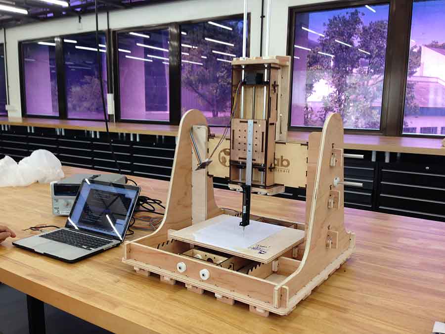
Satisfied with the motion control and the sample code, we further examined the features and the methodology to convert input files to coordinates. One of the features identified was to have the capability to jog the x, y, and z axis to approximate the distance of the end effector to the base plate. Since there are going to be different type of end effectors, each with its own quirkiness in terms of the height along z axis, the jog feature is good to have. The next features are the load function, to read in 2D or 3D files and to parse it as coordinates. Finally the 3 axis of the motion control was tested by hard coding the parameters and programmed to draw a square and a star on the fully assembled 3-axis machine we named Triple Axis Inscriber!
REFLECTIONS
The past 2 weeks had been challenging but rewarding to see an entire project of a 3-axis machine fabricated and assembled. This has been definitely eye-opening and hopes are high from the team that made it happen. Although the project hasn't been able to take into account of the end-user applications, this is surely an area of high interest and well-worth exploring in the near future. All-in-all, it's been a fantastic week!
Copyright © FabLab Singapore 2016