To view the group's MTM page, please click on this URL
Concepts & Methodology
For our group project, we have decided to build a 3axis machine with the use of gestalt boards, with swappable end effector. From the controlling the motion point of view, gestalt boards moves the stepper motors in coordinates, instead of the traditional gcode. From Nadya’s pygestalt example, the magic to move happens at this line of code moves = [[0,0,0], [20,0,0], [20,20,0], [0,20,0], [0,0,0],[0,0,10]] where elements in the array defines the absolute coordinate to move. Assuming if there is only 1 axis, the element in the array contains 1 figure; 2 axis, the element in the array contains 2 figures, separated by a comma; and so forth. This is the first time I came across such cool method to move stepper motors. By design, one could connect as many stepper motor as required by daisy chaining the gestalt boards as per described in this URL by Nadya.
The main challenge here is to figure out a way to transform the input files into the absolute coordinates mentioned above by code. Our machine is designed such that the end effectors are swappable; the end effector ranging from a pen, a milling bit, an extruder for filament, or even an extruder for chocolate. To 3D print with the 3axis machine designed and fabricated, one need to convert stl to the absolute coordinates. To 2D draw, one need to convert a png file to the absolute coordinates. Each of the file formats have it own’s quirkiness. The big question now is how much time we have to study on the different file formats and the methodology to convert it with code. In other words, we have to write a custom parser for each of the different input file types to transform into the absolute coordinates we are seeking to move the stepper motors.
Since this is meant to be a quick project, we decided to use a pen or marker as the end-effector for our machine. Being able to control the motion of the pen and draw different artwork that we pass to the parser means that we can build a vinyl cutter, laser cutter that required movement in 2D space because the basic principles are similar. To control motion of the end effector in 3D, requires a different parser all together.
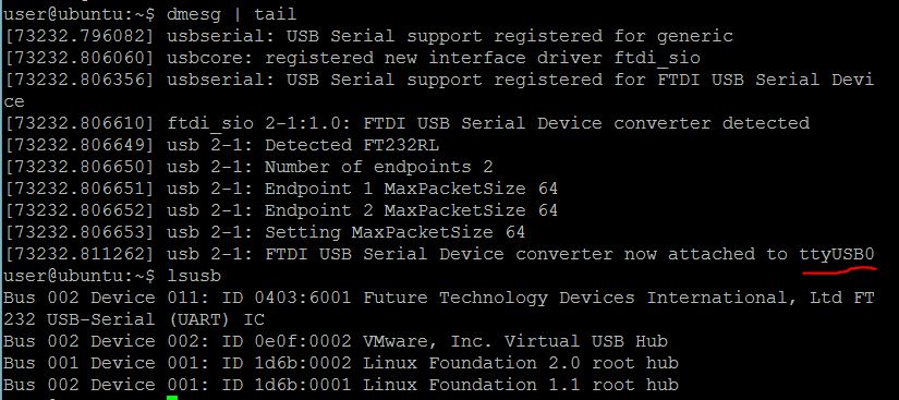
To make this task manageable and deliverable within a limited time frame while juggling between different commitments, we approached by: First we tested motion control with the sample code provided by nadya’s pygestalt singlenode.py using my linux machine connected to RS485, to fabnet and then one one of the gestalt boards. The following diagram describes the port used by my linux machine.
we then examined the sample code xyplotter in the same folder. Video of 2axis testing here
Satisfied with the motion control and the sample code, we then examine the features and the methodology to convert input files to coordinates. One of the features we identify is to able to jog the x, y, and z axis to approximate the distance of the end effector to the base plate. Since there are going to be different type of end effectors, each with its own quirkiness in terms of the height along z axis, the jog feature is good to have. The next features are the load function, to read in 2D or 3D files and to parse it as coordinates.
Finally we tested our 3 axis of the motion control by hard code the 3axis parameters used to draw a square on our fully assembled 3axis machine video here
Below is the code I implemented as manjog.py with function call for loading of SVG input files is available here. Mr.Chew also have done similar code s-xyz_test.py is available here.
input a 2D file and convert into absolute coordinates
There are many files that describes text or images in 2D, such as PNG, JPG, txt etc. We are quite worried on the sheer amount of files need to be considered for the said universal parser. Thankfully, Mr.Dorville’s MTM project URL from last year fab academy is online which gave me some idea and example on exporting SVG into absolute coordinates where I heavily referenced from.
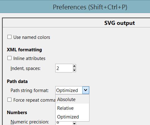
First inkscape need to be configured to plot path in absolute coordinates. Inkscape store the coordinates in an XML tree, where the variable d stores the data to be parsed into the absolute coordinates for gestalt board. The following picture describes the setting into absolute coordinates.
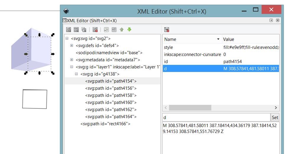
The following picture describes the XMT tree, with the variable d selected
The following codes describe the data contained in d for both absolute and relative coordinates. Note the uppercase M denotes absolute, whereas the lower case m denotes relative.
//====SVG rel vs abs======
//#relative
m 36.365234,926.3418 c 0,0 0,1.77148 0,1.77148 l -1.771484,74.75192 c 0,0 1.771484,0 1.771484,0 l 75.761716,1.7715 c 0,0 0,-1.7715 0,-1.7715 l 1.77149,-74.75192 c 0,0 -1.77149,0 -1.77149,0 l -75.761716,-1.77148 z m 1.730469,3.54297 73.990237,0 -1.72852,72.93943 -73.95117,-1.7285 1.689453,-71.21093 z

//#absolute
M 36.365234,926.3418 C 36.365234,926.3418 36.365234,928.11328 36.365234,928.11328 L 34.59375,1002.8652 C 34.59375,1002.8652 36.365234,1002.8652 36.365234,1002.8652 L 112.12695,1004.6367 C 112.12695,1004.6367 112.12695,1002.8652 112.12695,1002.8652 L 113.89844,928.11328 C 113.89844,928.11328 112.12695,928.11328 112.12695,928.11328 L 36.365234,926.3418 Z M 38.095703,929.88477 112.08594,929.88477 110.35742,1002.8242 36.40625,1001.0957 38.095703,929.88477
This page serves as an excellent lookup on the corresponding code found in the XML tree in inkscape mentioned above.
Fun fact: if a shape is drawn on inkscape first, then change to absolute or relative coordinates, one need to move the shape. Otherwise, the XML tree will not contained the value that reflects the change in coordinate preference. I learnt it the hard way. More details here.
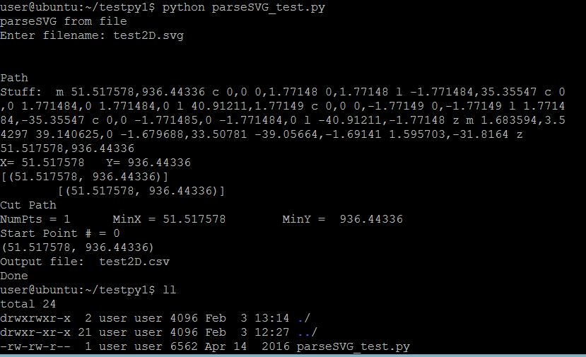
The following diagram describes the first iteration of parsing the variable d in the XML tree of an SVG file output into CSV files that contains the coordinates. This CSV file than can be fed into the gestalt boards. The parsing code ain’t pretty or functional yet. It is available here
input a 3D file and convert into absolute coordinates
I am still finding a way to convert from STL to absolute coordinates. First, I thought of using cura to convert from STL to gcode, and from gcode to absolute coordinates. Upon further inspection and reference from herehere, I realised the code G91 refers to relative coordinates instead of absolute. Hence my idea of extracting gcode and put into the elements will not work. I hope to learn how to convert stl to absolute coordinates from the kind people in fablab.