Exercise 09 - MTM (Mechanical Design)
Assignment
The machine building group project is split into 2 separate assignments. For this week, we are doing the mechanical design. We need to:
- Make a machine, including the end effector
- Build the passive parts and operate it manually
- Document the group project and our individual contribution
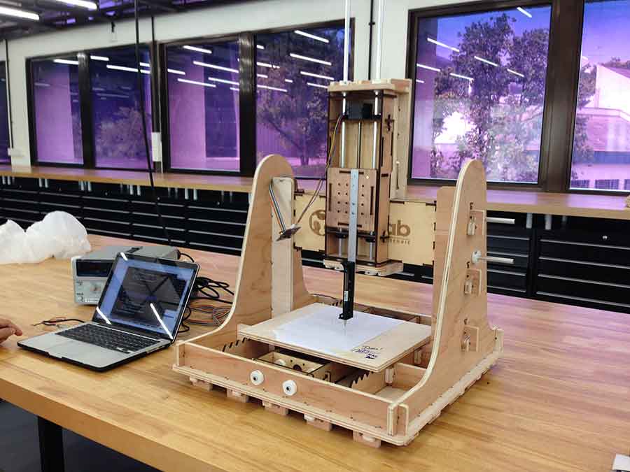
For our group project, we decided to build a 3-axis machine which is adaptable for different applications, simply by changing the end effector. Our group felt that being able to build and control the motion of a 3-axis machine gives us a lot of flexibility and potential for future machines that we build.
Since this is meant to be a quick project, we decided to use a pen or marker as the end-effector for our machine. Being able to control the motion of the pen and draw different artwork that we pass to it means that we can build a vinyl cutter, laser cutter, 3D printer and milling machine, because the basic principles are similar.
To view the group's MTM page, please click on this link.
Making the Interface Board
Our group is using the gestalt nodes for our machine. We need to first make the fabnet interface board for our gestalt nodes. A good reference is the Fab Academy Machine Building tutorial:Getting Started with Gestalt Nodes.
I designed my interface board based on Bas' design, which allows me to use a 10-way IDC cable to connect to the Gestalt nodes. I used this design for my fabnet interface board last year, so I know that it is a proven design.
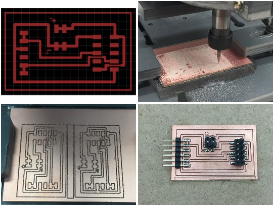

The Eagle board layout for my MTM interface board can be downloaded from here.
Installing PyGestalt
Before I could begin testing the gestalt nodes, I first had to install pygestalt. The code can be downloaded from Nadya's GitHub site:
http://github.com/nadya/pygestalt
After downloading and unzipping the pygestalt files, change to the pygestalt directory and run setup.py to install the software:
sudo python ./setup.py install
Once pygestalt has been setup, I could now test the gestalt nodes and familiarise myself with the framework. Nadya has included a number of examples in the pygestalt package. The examples are located in the examples/machines/htmaa folder. The first test I ran was to test a single machine stage. Nadya has helpfully included a file, single-node.py, which allowed me to run this test.
Understanding the PyGestalt Framework
The PyGestalt framework is based on the concept of a virtual machine. Within the virtual machine, the user defines:
- the interface for the machine (initInterfaces)
- the number of axis/nodes (initControllers)
- the coordinate system in use (initCoordinates)
- the characteristics of each axis such as number of microsteps, degrees per step, linear motion per revolution and direction
- public interfaces/functions: e.g. move(), jog()
- machine position
- spindle speed setting
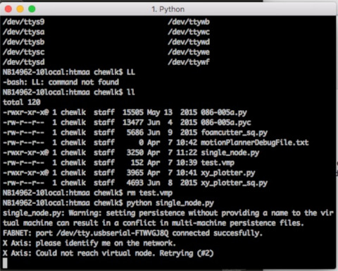
In order for the computer to talk to the gestalt nodes, we need to first inform it of the serial device that we are using. I haven't tried it on a Linux machine, but Nadya's default port for the RS-485 interface is "/dev/ttyUSB0". One my MacBook, portName is set to "/dev/tty.usbserial-FTXW6Q4L". On both Linux and OSX machines, to check the correct port name, type:
ls /dev/tty*and look for the entry that looks something like:
   ttyUSBx (Linux)
or tty.usbserial-FTXWxxxx (MacBook)
On a Windows machine, open device manager and look for the COMport associated with the RS-485 interface.
To run the single-node test, power up the system and type:
python single_node.pyThe PyGestalt framework initializes and tries to identify the X-axis node. A blue led blinks on the gestalt node. Press the pushbutton on the gestalt node to identify it on the network. Once all the gestalt nodes have been identified, a persistence file, test.vmp containing this information is saved in the project folder. If the machine configuration is changed, test.vmp has to be deleted and the nodes re-identified.
The program then runs. For this single node test file, the program simply moves the stage through 4 different positions, saved as a list of coordinates in the variable supercoords:
supercoords = [[10], [20], [10], [0]]
    for coords in supercoords:
	   stage.move(coords, 0)
       status = stage.xAxisNode.spinStatusRequest()
       while status['stepsRemaining'] > 0:
          time.sleep(0.001)
          status = stage.xAxisNode.spinStatusRequest()
Once all the moves in supercoords have been completed, the program ends.
The kinematics for both axes also has to be defined:
def initKinematics(self):
   self.xAxis = elements.elementChain.forward([elements.microstep.forward(4), elements.stepper.forward(1.8), elements.leadscrew.forward(8), elements.invert.forward(True)])
   self.yAxis = elements.elementChain.forward([elements.microstep.forward(4), elements.stepper.forward(1.8), elements.leadscrew.forward(8), elements.invert.forward(False)])
   self.stageKinematics = kinematics.direct(2)	#direct drive on all axes
Since there are 2-axis, each point in moves also has 2 values, representing the [x,y] coordinates of the point:
moves = [[10,10],[20,20],[10,10],[0,0]]
The end of the move sequence occurs when there are no more spinStatusRequests. I only need to check the request on any one of the axis; there is no need to check spinStatusRequest on all the axes on the virtual machine.
for move in moves:
   stages.move(move, 0)
   status = stages.xAxisNode.spinStatusRequest()
   # This checks to see if the move is done.
   while status['stepsRemaining'] > 0:
      time.sleep(0.001)
      status = stages.xAxisNode.spinStatusRequest()
Revised MTM Interface Board
In my original design of my MTM interface board, I omitted the 680 ohm pull-up and pull-down resistors on the data wires. I made the assumption that somewhere in the bus, pull-up and pull-down resistors existed. My interface board on 2 machine stages during testing.
I decided to read further about the RS-485 standard and the wiki article states that "somewhere along the set of wires, pull-up or pull-down resistors are established to fail-safe bias each data wire when the lines are not being driven by any device, so that the data lines are biased to known voltages and RS-485 nodes will not interpret noise from undriven lines as actual data."

With this in mind, I redesigned my MTM interface board to include a pair of 680 ohm pull-up and pull-down resistors on the data wires, to provide fail-safe bias voltages for these lines.
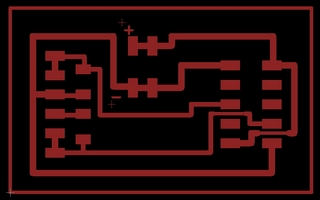
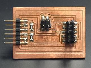
The eagle board layout for my updated MTM interface board: new MTM interface board