2016
Communications and Networking May 11. 2016
This week it was time to make two MCUs to talk to each other. I desided to do couple of exercises for this one. I have done some XBee networking previously with RaspberryPi and this time I try to integrate them with Atmel based Arduinos. I have also ordered couple of XBee Arduino shields so I’m able to concentrate on the networking code generation and after that part is ready I can build the MCU boards.
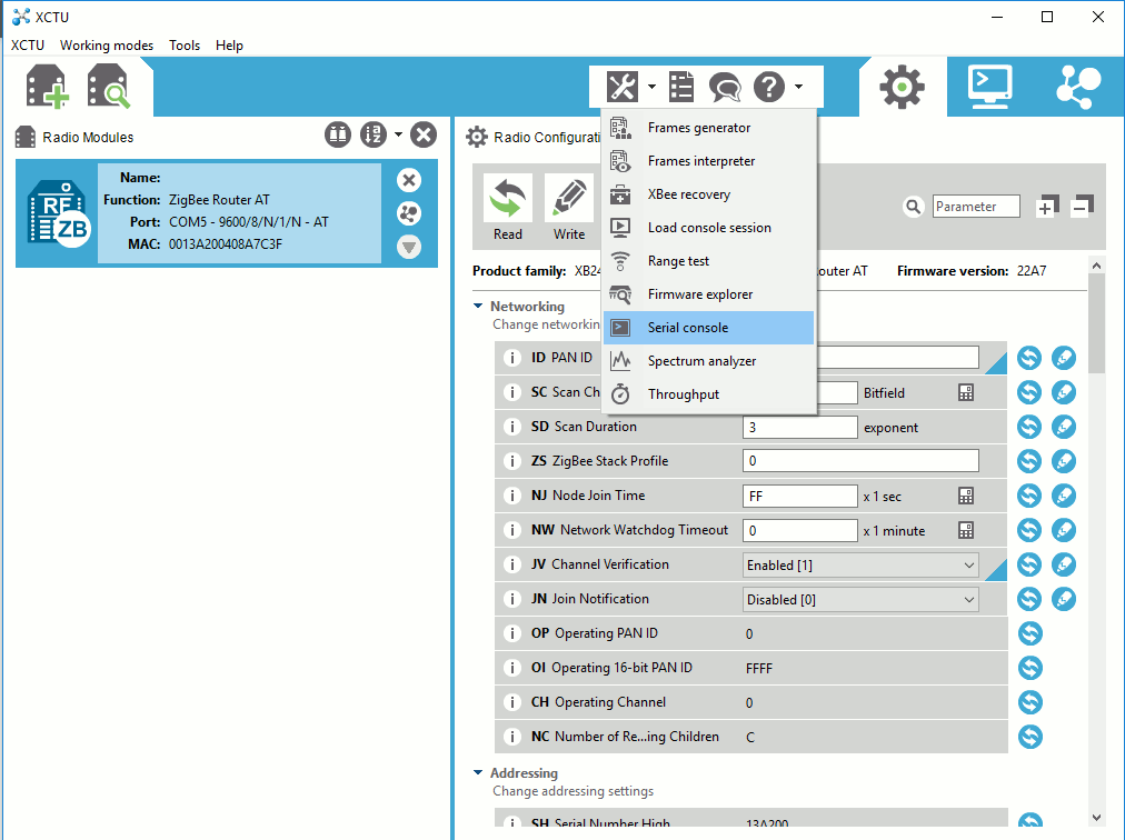
XCTU is the program that you need to use for configuring XBees to act as a router or an end device as well as their address can be determined.

Configuration can be done either by editing the parameters on the right side window or through Serial console with AT commands.
The addressing scheme consists the following terms: PAN ID, MY address, and destination address. In addition, there is the radio frequency channel that all the nodes in the network needs to be assigned. All the nodes that share a same PAN ID can communicate to one another and destination address is the target for the message and a node with MY address equal to the destination address will be the recipient of that message. XBee’s can share the same MY address and both receive the same data if it’s sent to that address. The MY address can be any value between 0x0000 and 0xFFFF. This goes nto the text box next to “MY 16-bit Source Address” in XCTU configurator. There are actually two values used to set the destination: destination high (DH) and destination low (DL). Coordinator actually decides on the router (client) addresses.
Here is an example that can be used to define two nodes that can communicate to each other. The high and low addresses can be checked from the back of the XBee modules.
|
Setting |
Acronym |
XBee 1 coordinator |
XBee 2 router |
|
Channel |
CH |
C |
C |
|
PAN ID |
ID |
6B1D |
6B1D |
|
Destination Address High |
DH |
0013A200 |
0013A200 |
|
Destination Address Low |
DL |
408A7C3F |
4033D008 |
|
16-bit Source Address |
MY |
0 |
Defined by coord. |
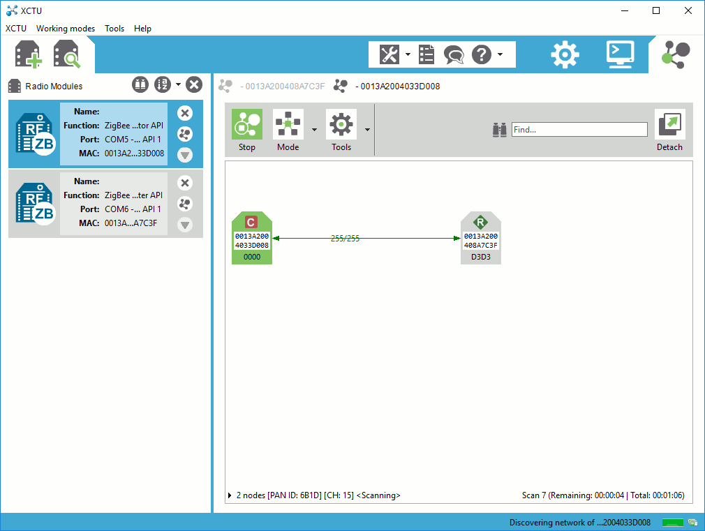
Nice feature in XCTU is the graphical topology view where you can actually check the network connections in graphical view.

A coordinator with two routers that have formed a network.

Once you have set up the XBees to function properly and form a network they can be inserted into MCU platform and work as transmission media between two or more MCUs.
I had purchased two redesigned Arduino Pro Mini copies from Ebay couple of years back and to save huge amount of time of making them myself, I decided to harness these with XBees and make some simple communication between them, If time permits, I will design a motherboard for the Arduino Pro Mini and XBee.
In order to program Arduino Pro Mini, I need a USB serial interface such as FTDI serial cable. Similar cable can be used to configure XBees as well.
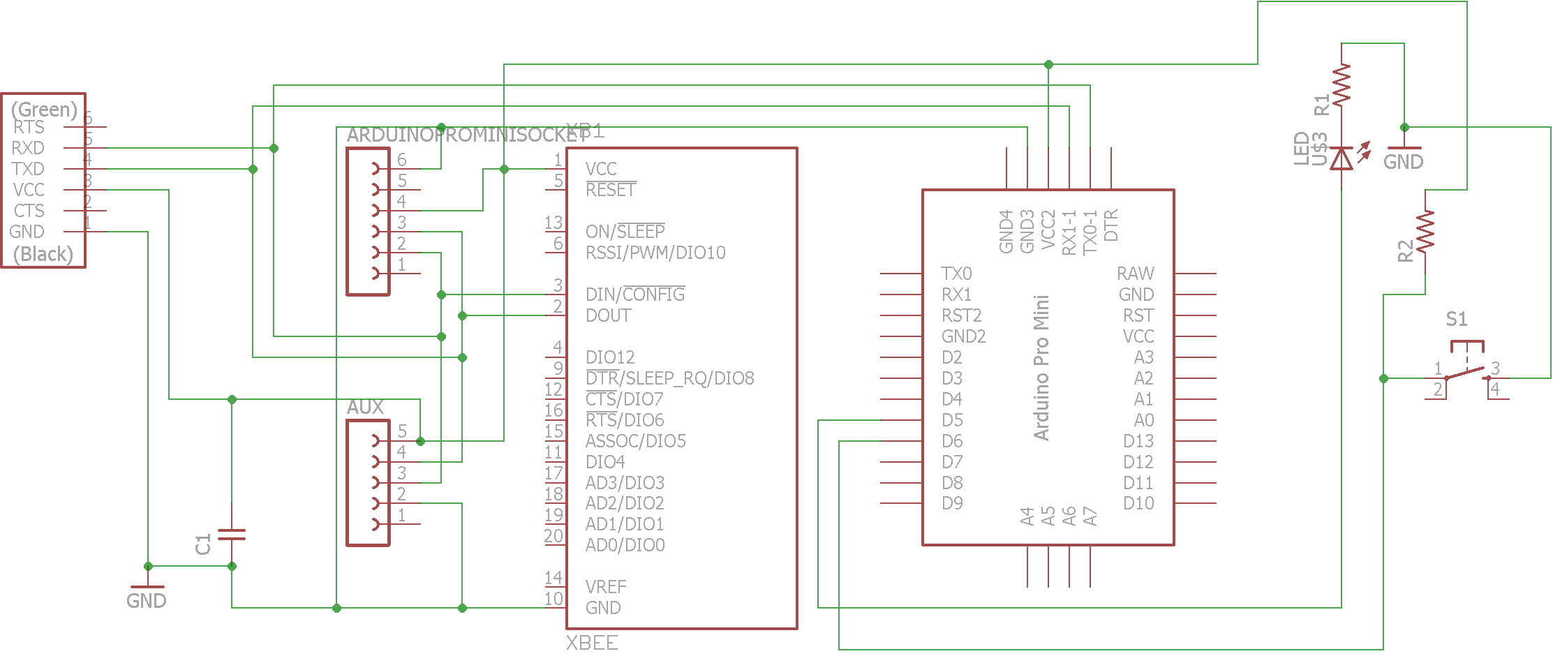
Here is the schematic for the motherboard coecting Xbee and Arduino Mini Plus.


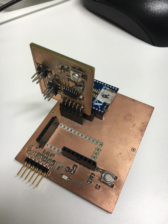
This is a double sided board and 8 vias. For vias, I used rivets for 0.8 mm hole. I placed a FTDI connector for power feed with additional two sockets for vertical Arduino placement and additional USB serial adapter with 3.3v power. XBee and the microcontroller board are connected through sockets.
Here are codes for Arduino based end device and coordinator for blinking led remotely.
Node 1 code:
int BUTTON = 6;
int LED = 5;
void setup() { pinMode(BUTTON, INPUT); Serial.begin(9600);
pinMode(LED, OUTPUT);}
void loop()
{
// send a number 1 over the serial port if the button is pressed
if (digitalRead(BUTTON) == LOW) { Serial.print('1');
digitalWrite(LED, HIGH);
delay(300); // prevents overwhelming the serial port
digitalWrite(LED, LOW);
}
}
Node 2 code:
int LED = 5;
void setup() { pinMode(LED, OUTPUT); Serial.begin(9600); }
void loop() {
// look for a capital D over the serial port and ring the bell if found
if (Serial.available() > 0) { if (Serial.read() == '1'){
digitalWrite(LED, HIGH);
delay(300);
digitalWrite(LED, LOW);
}
}
}
In order to use my own boards, I replicated the board from week 6 (Electronics production) and used the board from that week. I connected the boards to Xbee with the board shown above and 3.3v FTDI cable and with USB - Xbee interface and hookup wires. We also need to use some other means for making serial communication from the ATtiny44a microcontroller. The board developed here can also be used but we use ready made XBee USB adapters.

We can easily utilize the information learned from week 8 and hello.ftdi.44.echo.c from the same week. The result is an edited hello.ftdi.44,c with the following main function and changed definition for 9600 baud rate (100 was used in week 15 lectures example). The following is the coordinator node code that enables sending of character ‘p’ that can also be used as an address if multiple routers are in the same PAN.
#define bit_delay_time 102 // bit delay for 9600 with overhead
int main(void) {
//
// main
//
static char chr;
DDRB = 0b00000100;//Makes 2nd pin of PORTB LED as Output
DDRA = 0b01111111; //Makes 7th pin of PORTA as Input
//
// set clock divider to /1
//
CLKPR = (1 << CLKPCE);
CLKPR = (0 << CLKPS3) | (0 << CLKPS2) | (0 << CLKPS1) | (0 << CLKPS0);
//
// initialize output pins
//
set(serial_port, serial_pin_out);
output(serial_direction, serial_pin_out);
//
// main loop
//
while (1) {
if((PINA & (1<<PA7))==0) //If switch is pressed (Normal active)
put_string(&serial_port, serial_pin_out, "p");
get_char(&serial_pins, serial_pin_in, &chr);
if(chr=='p')
{
PORTB |= (1<<PB2); //Turns ON LED
_delay_ms(1000); //1 second delay
PORTB &= ~(1<<PB2); //Turns OFF LED
}
}
}
The router has to be configured without the additional DDRA statement. This remained a mystery as sometimes the same code in both nodes worked and often not. Somehow the led pin setting is false and despite several hours of problem solving, remained unsolved. The router does not need the button functionality. The provided solution makes the implementation robust simplex link and has the addressing capability within the code as well as in the wireless modules.
Now, if the XBees are configured as coordinator and router, the led of the end device can be blinked by the coordinator when the button of the coordinator is pressed.