Network communication
Assignment:
1. Design and build a wired and/or wireless network connecting at least two processors.Design & program the network.
This week I'm going to design and build a network based on serial asynchronous communication.
I'm making one bridge board and two nodes.
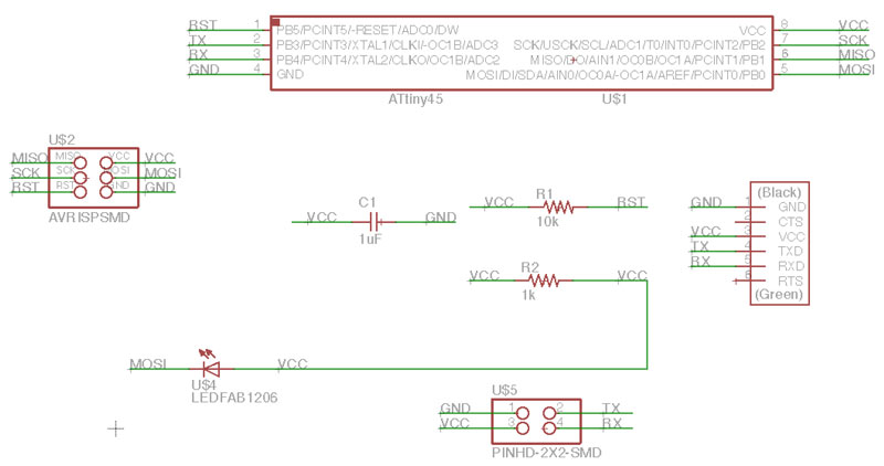
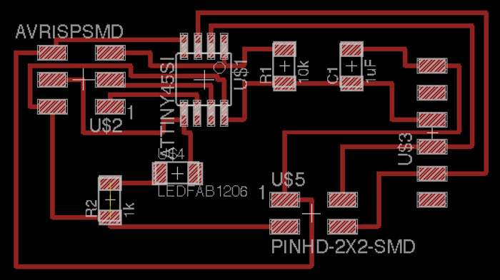
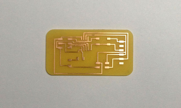
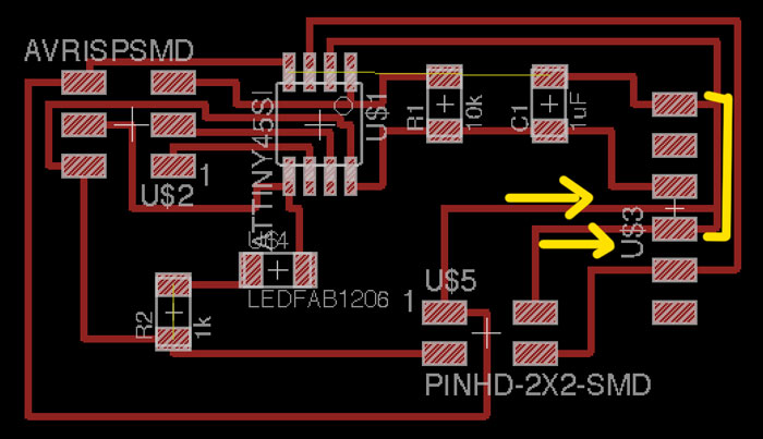
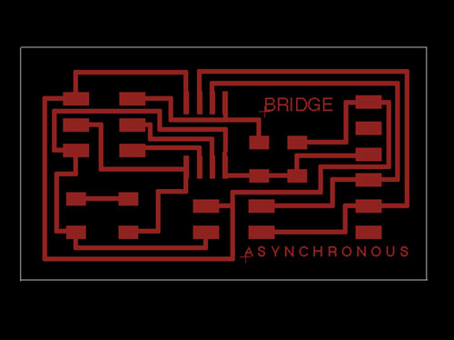
The next images show the bridge board schematics and design.
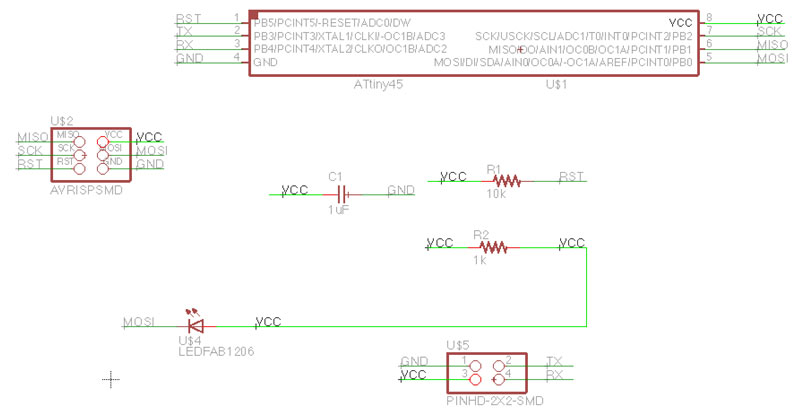
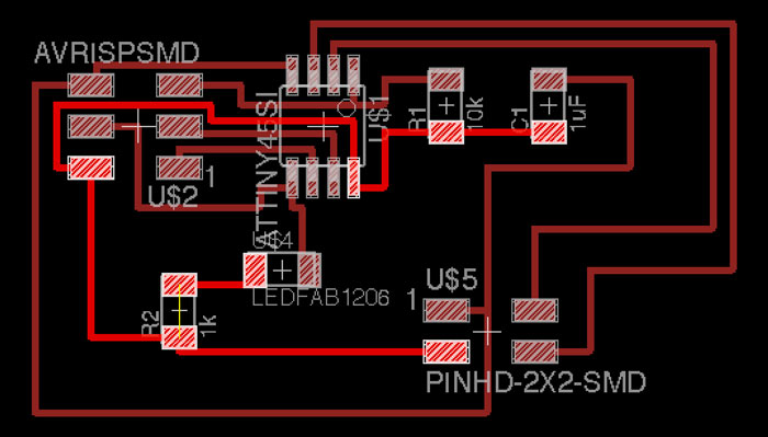
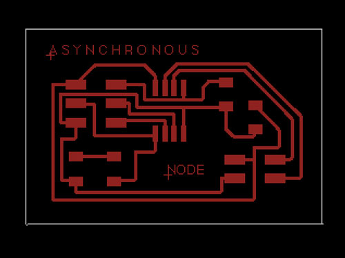
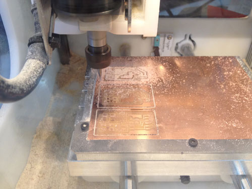
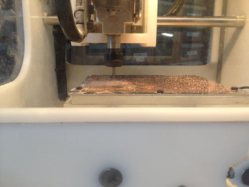
The next two images show the node board. I milled two of these.
This time I decided to get rid off the whole copper. For do this, you just need to set (in the 1/64 process) the offset to -1.
Once the boards are stuffed is time to upload the c code.
With the c file and make file on same folder I used terminal for uploading the code.
On terminal I located my folder with the c and make file.
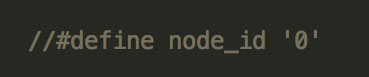
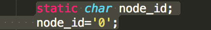
On the c file you need to change the #define node_id '0' for each node.
I used, for the bridge board: #define node_id '0'
For the first node: #define node_id '1'
For the second node: #define node_id '2'
And type the "sudo make -f hello.bus.45.make program-avrisp2" or "sudo make -f hello.bus.45.make program-usbtiny". For each board.
The workflow you should follow is: first connect the bridge board on one side to the FTDI and on the other to the FabISP or AVRISP and program it with the make file and c file that you change the node id to 0. Then you connect the first node to the bridge with the network cable and the FabISP or AVRISP and program it qith the c and make file that have the node id set as 1. Finally, you connect the the last node and follow the same workflow as node 1.
On first try I got an error: SCK fail.
The problem was that my bridge board got and error and I had to mill it again. As you can see I messed up the GND with the TX.
Here is the error fixed.
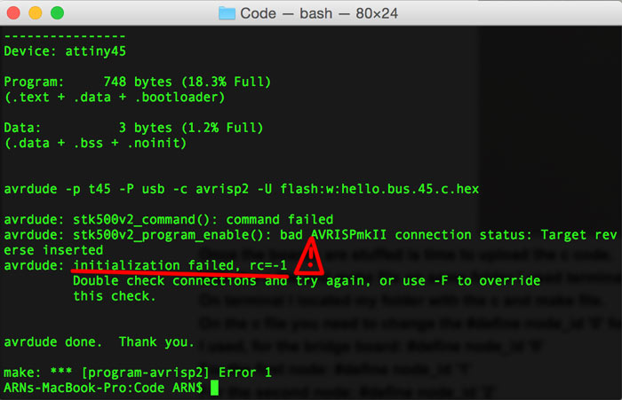
After fixing this I got the error: Unknown status 0x00
So I checked the connections, resoldering. And everything worked as a charm.
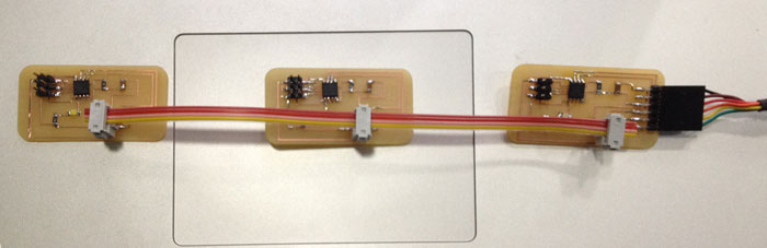
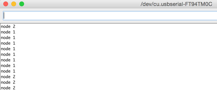
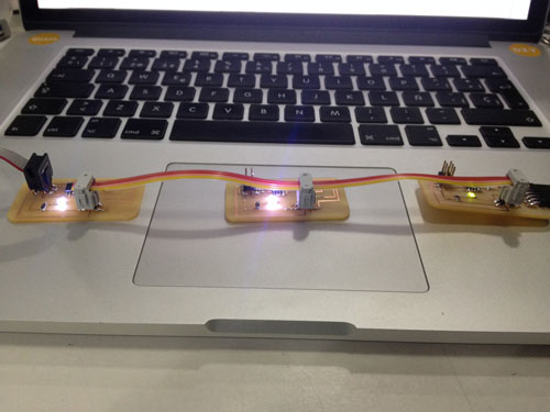
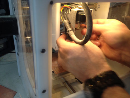
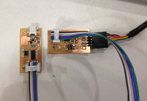
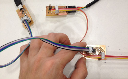
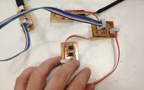
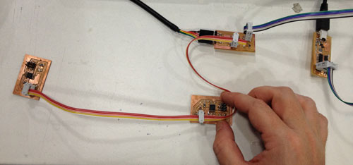
This are the boards connected to the network.Next, you load the Arduino IDE, and click on the Serial Monitor button. On the Serial Monitor window you type 0, 1 or 2 and press enter after the node you typed. Then you should get your boards react. The node selected should blink twice and get a response on the serial monitor window. I've got some problems in that stage.
I did not get response from two of the nodes, so, my classmate Xavi suggested me to change the change the c code a little bit.
I commented the global variable node_id.
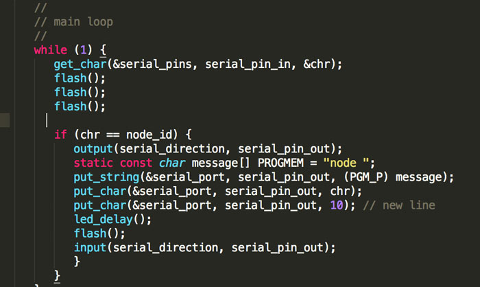
And included into the while loop.This trick made react one more node. The problem is that I still don't get response from the node 0.Because I was not happy with the result I tried changing the code a little bit more.
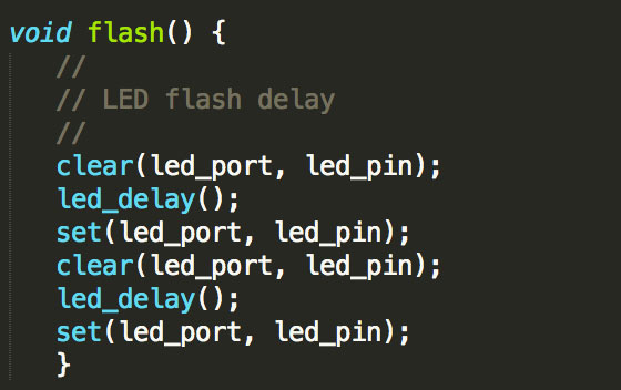
First I changed the while loop trying to make the LED blink different times. But I did not work. The next image shows the code.Then I changed the delay to 1000 ms, but the delay was more than a second. At this point I thought that I had some problems with the timer.Then, I though about why is not the flash function working, in the sense, that is not going through the all statements in the function.I changed the code, adding again the three statements.And I made some versions of this modification like only using the set function or the clear function. But I did not work.
I also tried to upload the blink example from Arduino changeing the LEDpin to 0, because I'm using and ATtiny45. The boards blink as expected.The password for the video is: fablab
In this video you can see how they blink as expected.
I even made a new cable for connecting the boards. And tried my boards in other computers, both Mac OS and Windows OS, I did not try on Linux, though.
My instructor, Ferdi, helped me in the debugging process. But not even two minds trying to solve the problem came out with a solution.
I checked my Eagle files for the last time, and the connections are the same as Neil's board, same pins, same code... I don't undersandt why I get feedback from just one node.
The password for this second video is fablab
Here is a video working just the second node.
At this point I decided to mill again the 3 boards, and try for the last time.
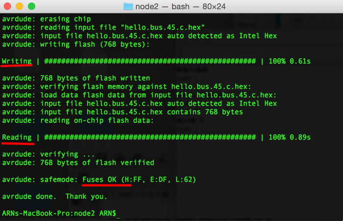
So I designed the boards again.This time I wanted to try the Othermill. My classmate Andy owns one I tried to mill with it: I used the Otherplan software. I milled with the 1/64 for the small traces, then changed to the 1/32 for finishing the traces and cut the outline. I don't know why but the text didn't came out. Maybe there are some options that need to be tweek on the Otherplan software.Because I was getting an orange blinking light with the AVR programmer (this could be a connexion problem or a problem with the RESET of the FTDI). Since Neil's design the RESET is not used i figured out that could be this my problem.So I decided to use my FabISP for programming. And everything worked like a charm. I managed to program the boards.The workflow is, as I said before, change the C file the node (0 for the bridge, 1 for the first node, 2 for the second node). Put the C file and the make file in the same folder, navigate via terminal to the folder. Connect the FabISP to the bridge type: "sudo make -f hello.bus.45.make program-usbtiny": If you get the message "Fuses OK". Do the same connecting the first node to the bridge and to the FabISP. Repite the process with the C file and make file changing the node to 1. Do the same with the second node. Once the boards are programmed. Boot Arduino, in the Tools menu set the Board to ATtiny, Processor: ATtiny45, Port choose your FTDI name. Open the Serial Monitor window and type 0 press enter. The LED from the bridge should blink and get response from the Serial Monitor. Type 1 press enter: The LED from the 1st node should blink and get response from the Serial Monitor. Same porcess for the second node.The password for the video is: fablab
Here is the video with the Asynchronous Serial Communication working.
>Download the files here