Mechanical and machine design
Task: | automate your machine; document the group project and your individual contribution
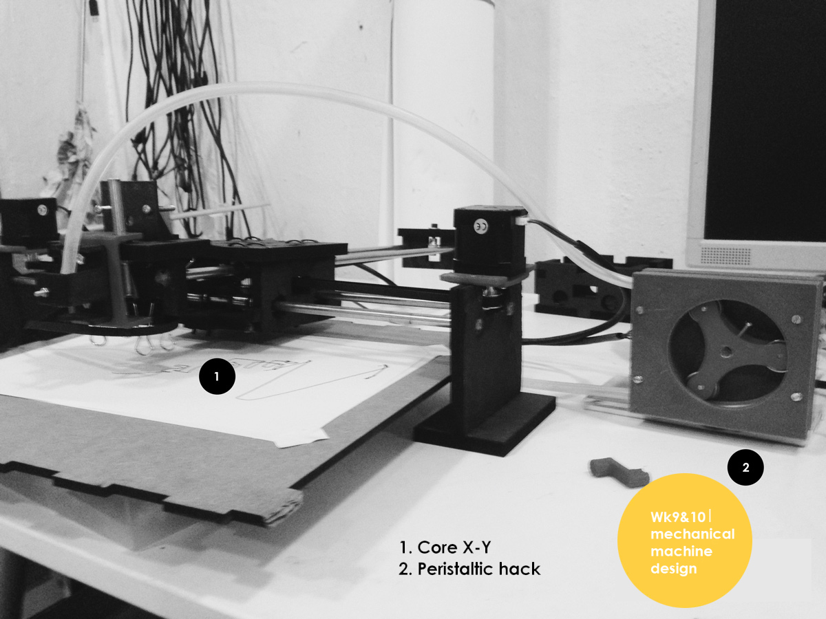
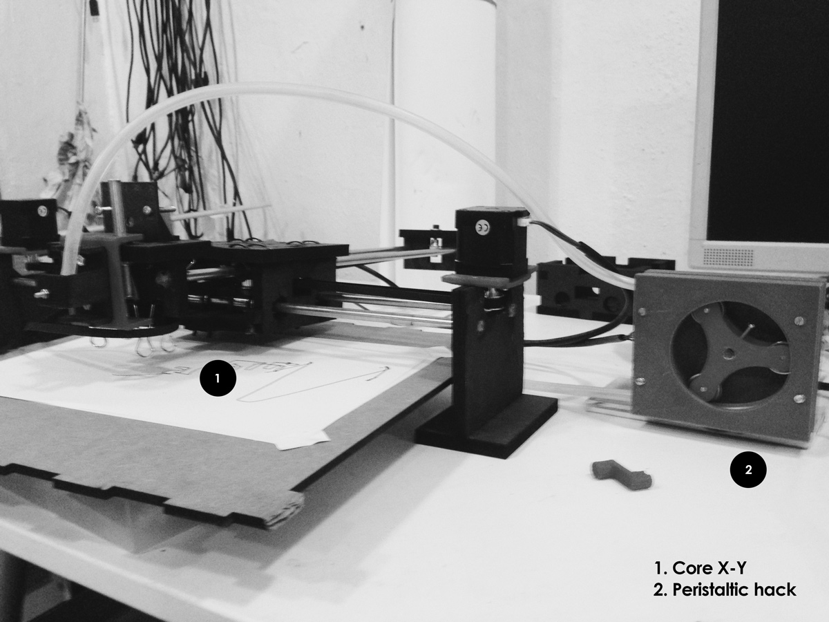
During this week the team and i developed the xy-core; my task was to progress with a tool which could hack onto the xy-core and eventually develop the modular mechanical system further. I was a week late into the group work due to the change in time calender at the time; but i made an extra effort to understand what the others were doing so that i could eventualy catch up and be the end-effector of the group.
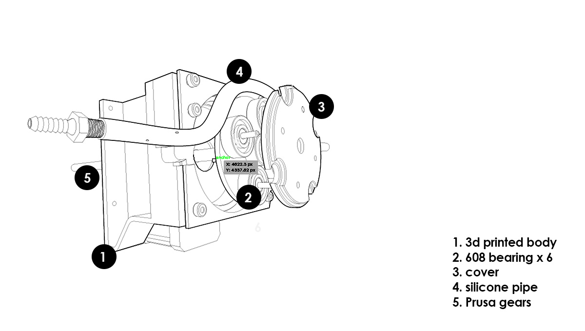
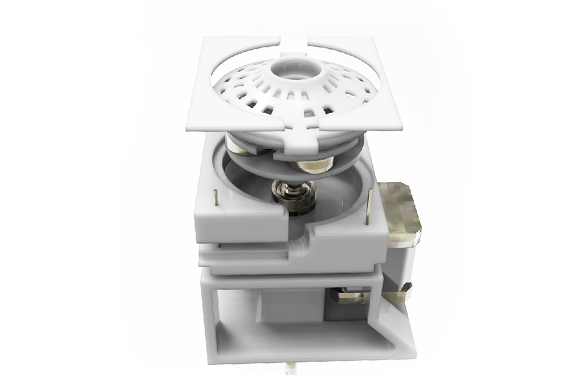
The above shows the mechanical design i developed so far for peristaltic pumps based on examples i saw online. This pump provides pressure by the movement of a constriction along a tube, similar to biological peristalsis.
As electronic hardware, my hack would act as the third stepper Gestalt node on the xy-core.
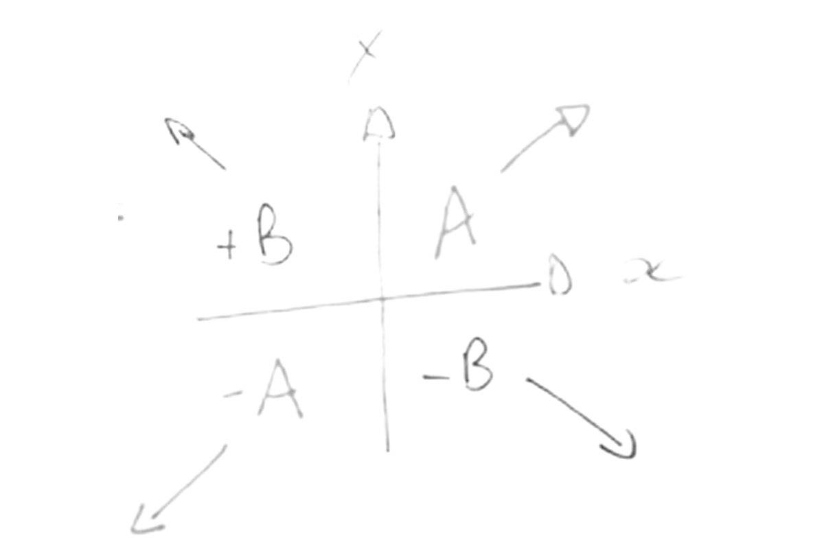
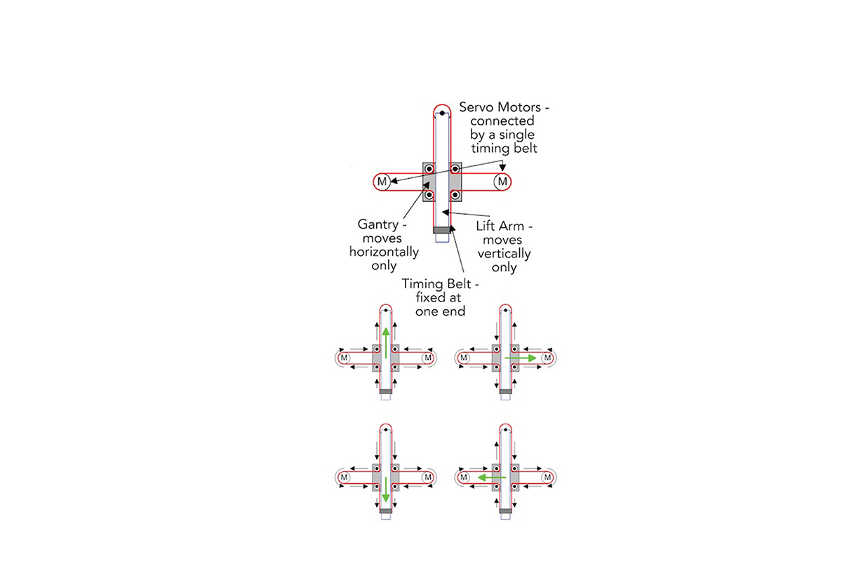
This was a study on xy-core to understand the mechanic movement
 Reference
EQUATIONS OF MOTION A,B: MOTORS
incX = 1/2(-incA-incB) neg_incX=1/2(incA+incB)
incY=1/2(incA-incB) negincY=1/2(-incA+incB)
diaA =incX+incY
neg_diaA= -incX -incY
diaB=-incX+incY
neg_diaB=incX-inxY
Once the others had developed their mechanics I was in time to understand equations of motion and programming with Gestalt nodes (although i developed the final with Marlin Firmware).
|Programming with Gestalt
1. Download Python 2.x for gestalt.
2. Download Python IDE or Python interpreter (IDE options)
Although one can use their terminal as an interface ... we suggest Pycharm as it is easier to understand and learn.
3.Getting started (helpful tutorials for beginners)
Gestalt is a control system framework for personal fabrication - look at this links to understand the framework 01 and 02
|Step by step for Geshtalt.
a. follow the set-up guide
b. Download pyGestalt Framework and install it.
--> in the directory where setup.py is:
sudo python ./setup.py install
c.Programming the Gestalt Node with and AVR
d.Download and Install pyserial -> in order to talk over serial
-pySerial is a module to communicate python with the serial port ( Python Serial Port Extension ).This is the installation guide
sudo python ./setup.py install
|Installing Pyserial and pyGestalt from the terminal on Mac.
a. Download and extract pyserial.
b.Navigate via Terminal to the folder you have pyserial extracted, in this folder you should have a file called setup.py
c. Run this script
sudo python setup.py install
A similar process should be done for the pyGestalt
a. Download the Nadia Peek pyGestalt framework.
b.Navigate in the command line where your pyGestalt folder is located.
c.Run the command: sudo python setup.py install.
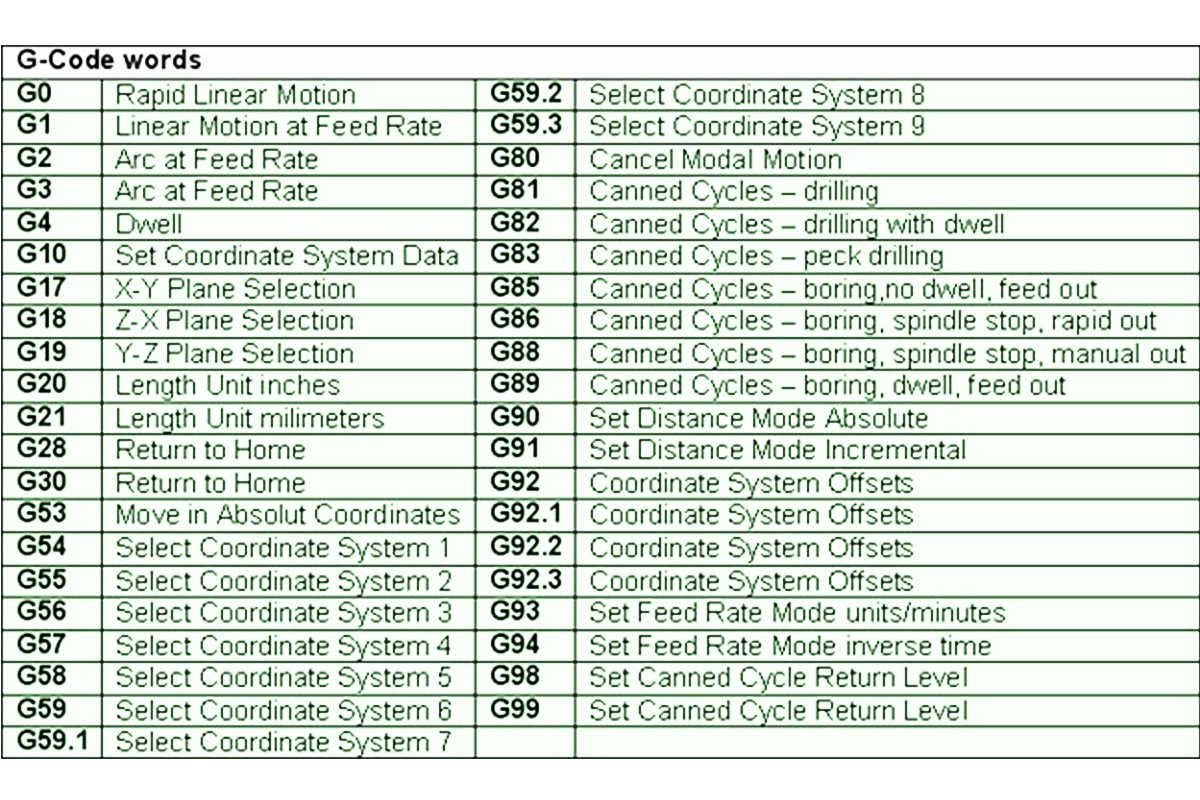
Generate G-code tutorial
 |Hardware:
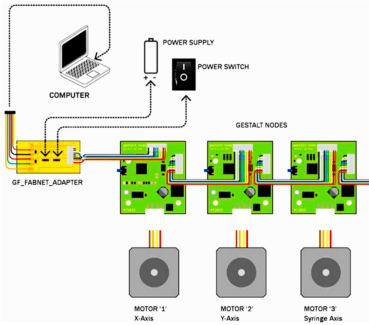
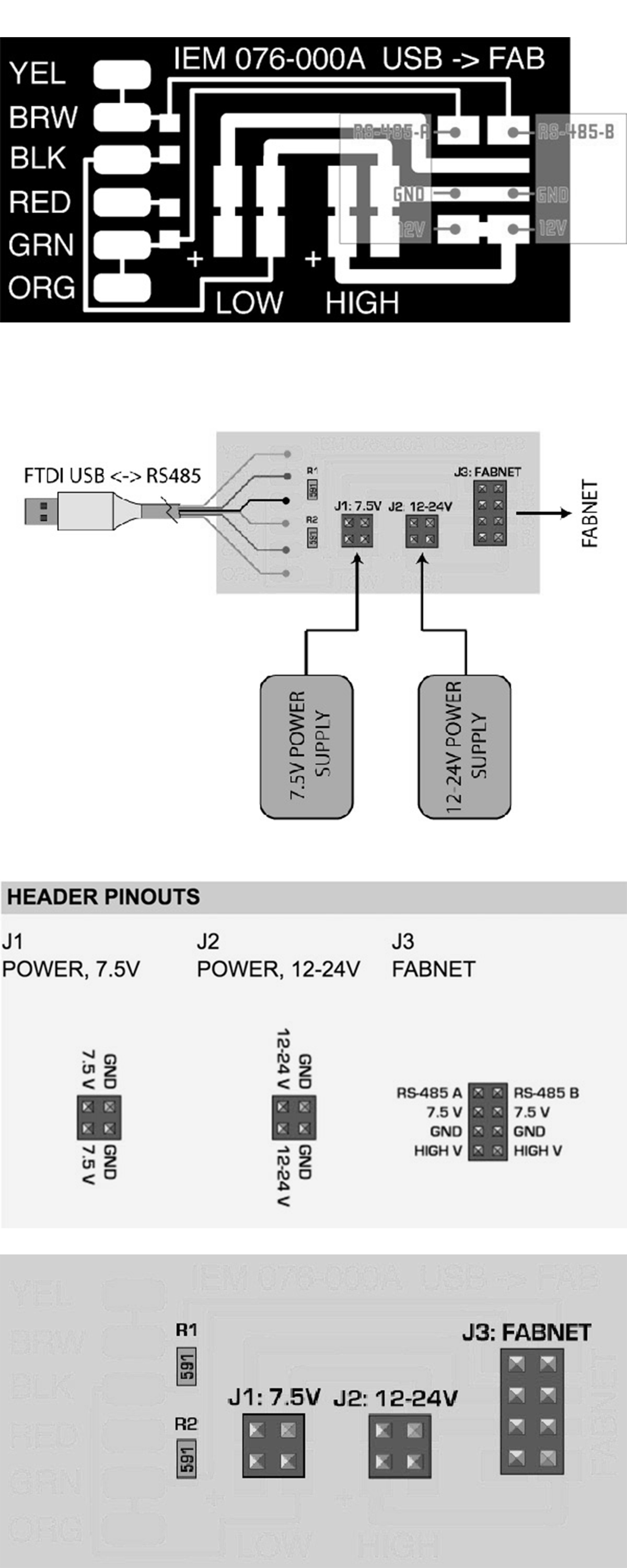
For the electronics, we needed to mill the FabNET board to use it with RS-485 usb connectors:
Fabnet is a multi-drop network, meaning that multiple modules (a.k.a. nodes) share a single set of communication wires. Signalling is differential based on the RS-485 specification. Each node is assigned a four-byte IP address which uniquely identifies it over the network.
Fabnet provides power at two voltages: high voltage (12V - 24V) is intended to drive motors, lamps and actuators, while low voltage (7.5V) supplies power to the logic circuits of the nodes.
Establishing connectivity between nodes and a computer, and providing proper power, requires several components: high and low voltage power supplies, a USB-RS485 converter cable, and an adaptor board (076-000A) with bias resistors.
The next images are some diagrams to understand how the FabNET connects to Gestalt boards and power supply.
Xavi Dominguez: Programming Download files
Arnau Tàsies: Graphic Design / 3D Modelling Download files
João Leão : Electronics / 3D Modelling Download files
Katerina Labrou: 3D Modeling / Programming
|more on the extruder
This was the very first extruder i worked on; which still required a lot more details to work.
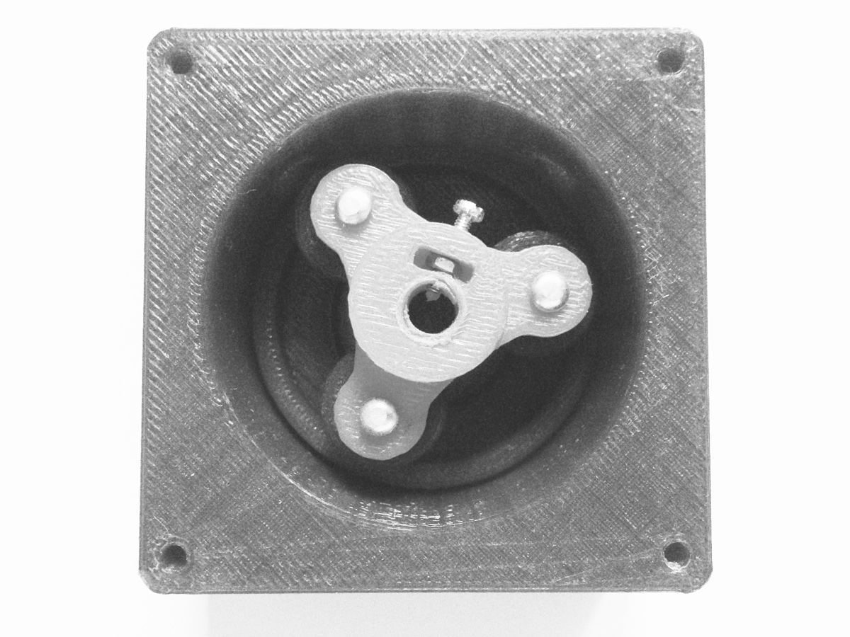
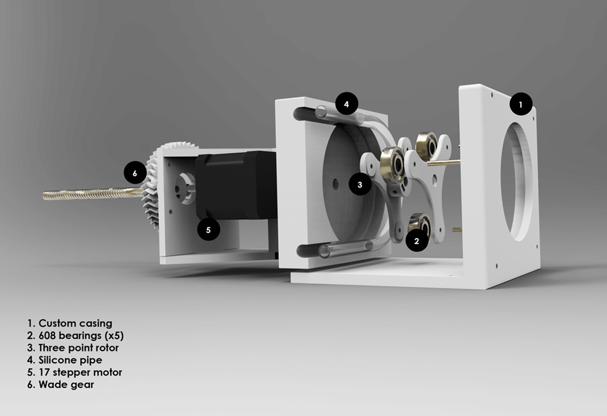
Below shows a grasshopper definition i wrote for a peristaltic pump. The pump squezes a silicone pipe and thus creates pressure which allows accurately controllable extrusion. A number of tests were made untill I had minimal friction and could get it to work properly. The process requires accurate fabrication, detailing and power.
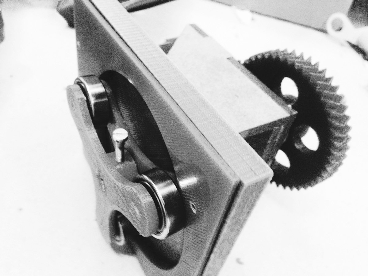
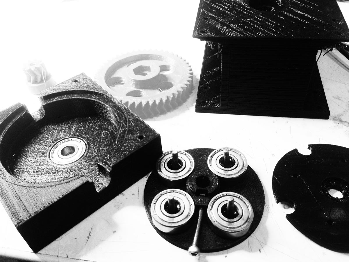
 A few attempts were made to get the mechanics of the pump right and the main inspiration came from reading such blogs as that of Frank Zhao . I discovered that precise fabrication with a goal to create minimum friction is the most important thing for these pumps to work properly. It also needs maximum power using electronics and tools available in the lab. This was the process:
1. Create a herringbone gear (more silent than the usual) This would add more power to the stepper motor by making it approximately 5 times slower in this case (47/9 ratio).
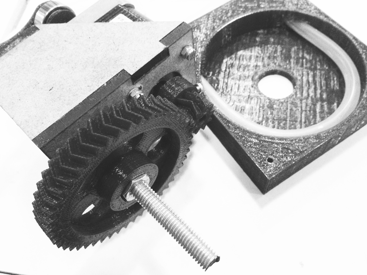
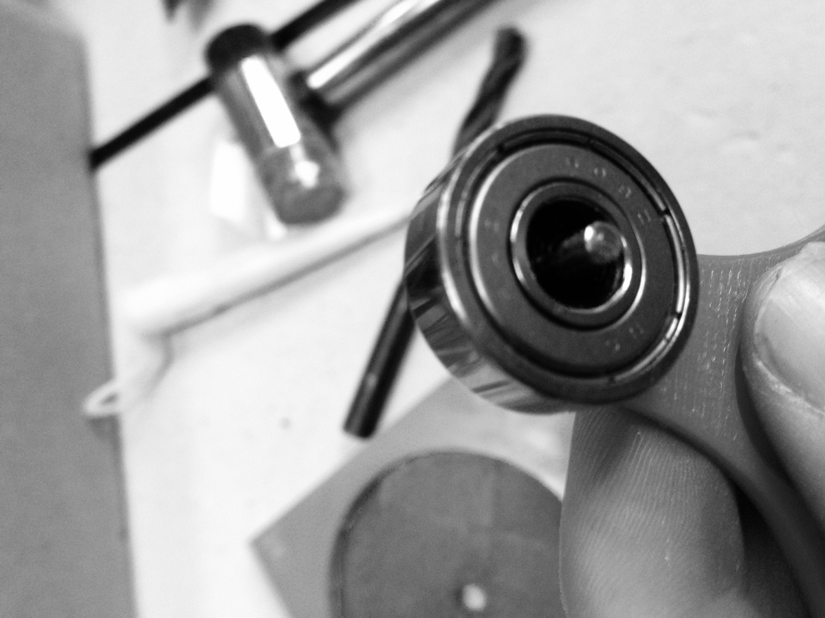
2. Add ball bearings (608) as wheels and to keep the shaft in accurate position by placing one on each axis.
3. larger more accurate body and rotor
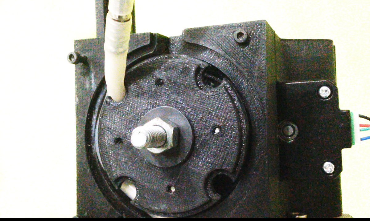
Ive been perfecting joints by custimizing different parts, 3d printing small fillers and chasing and filing 3mm bars.
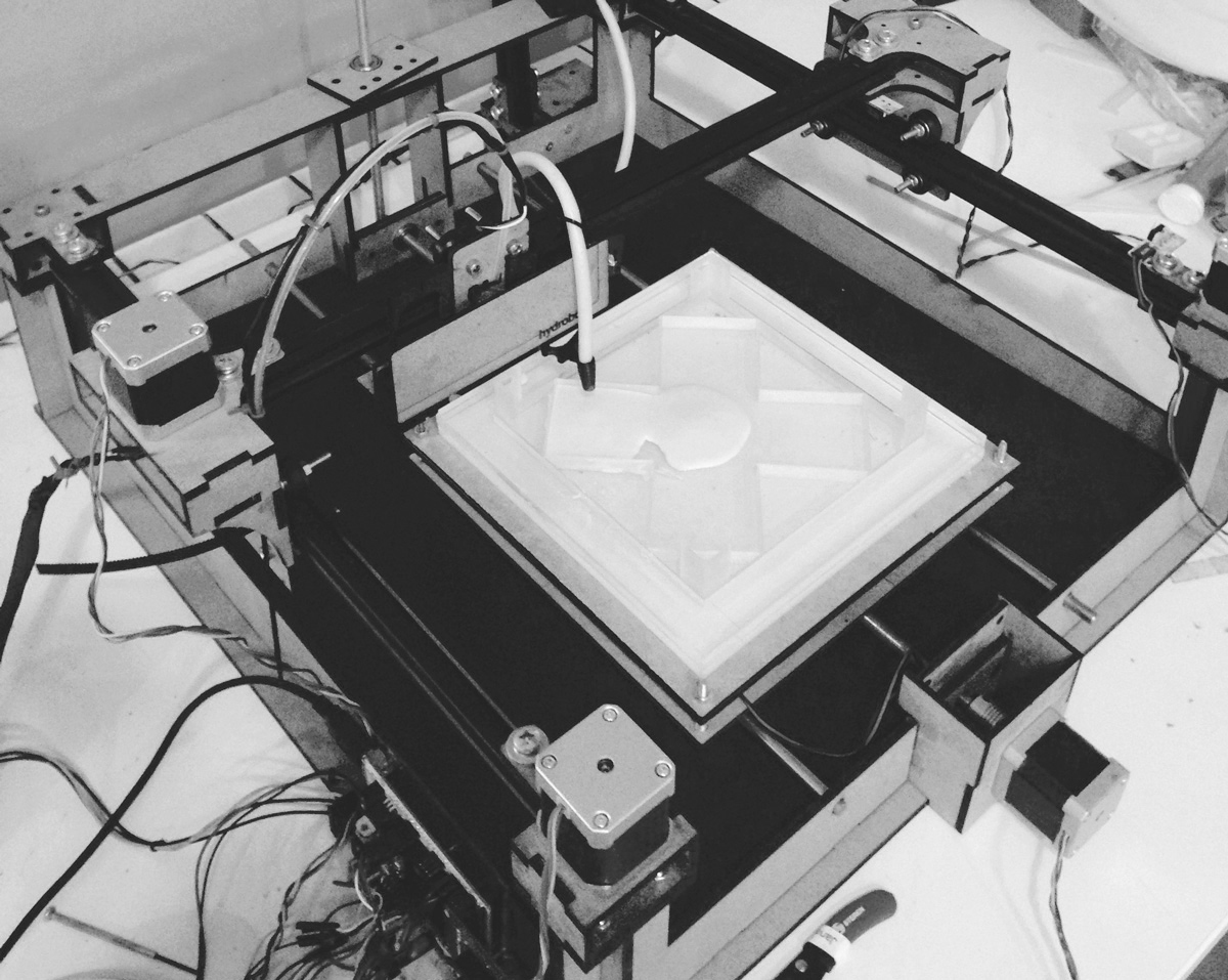
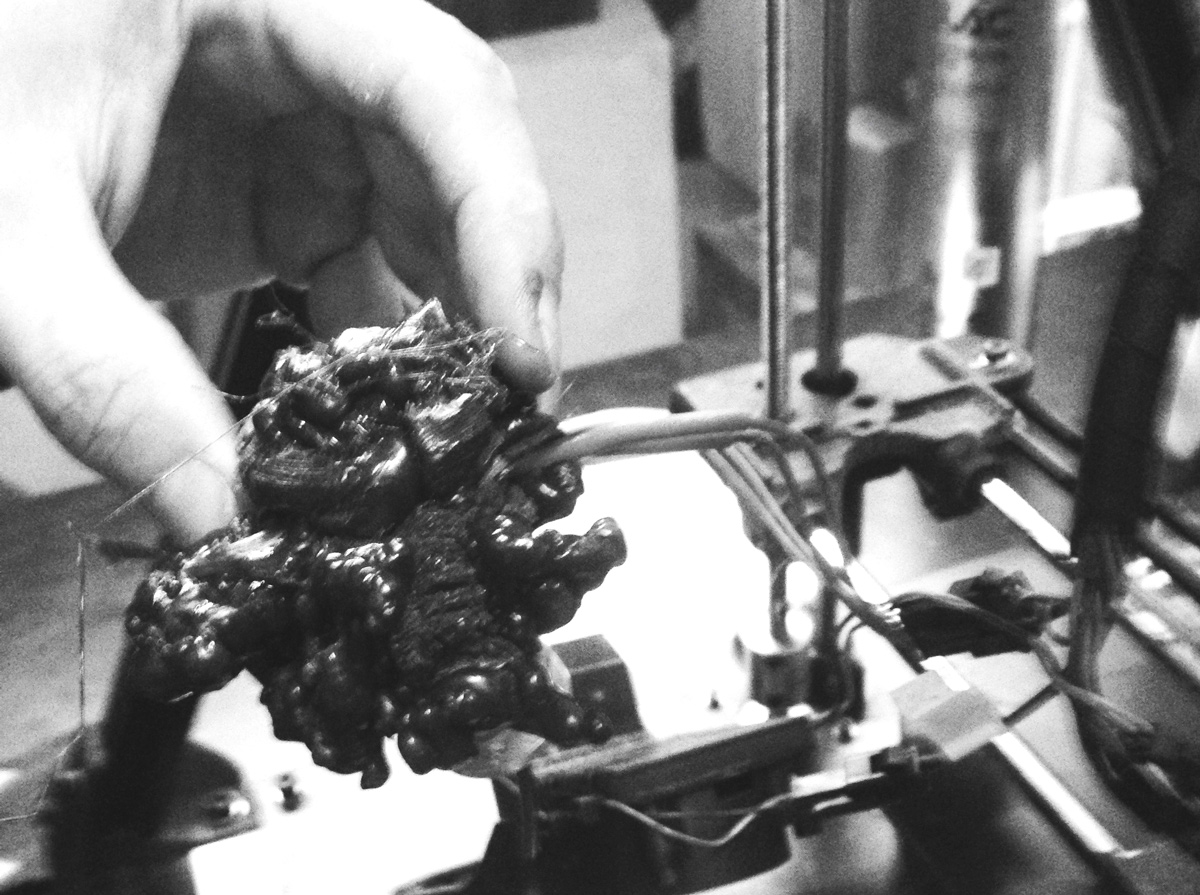
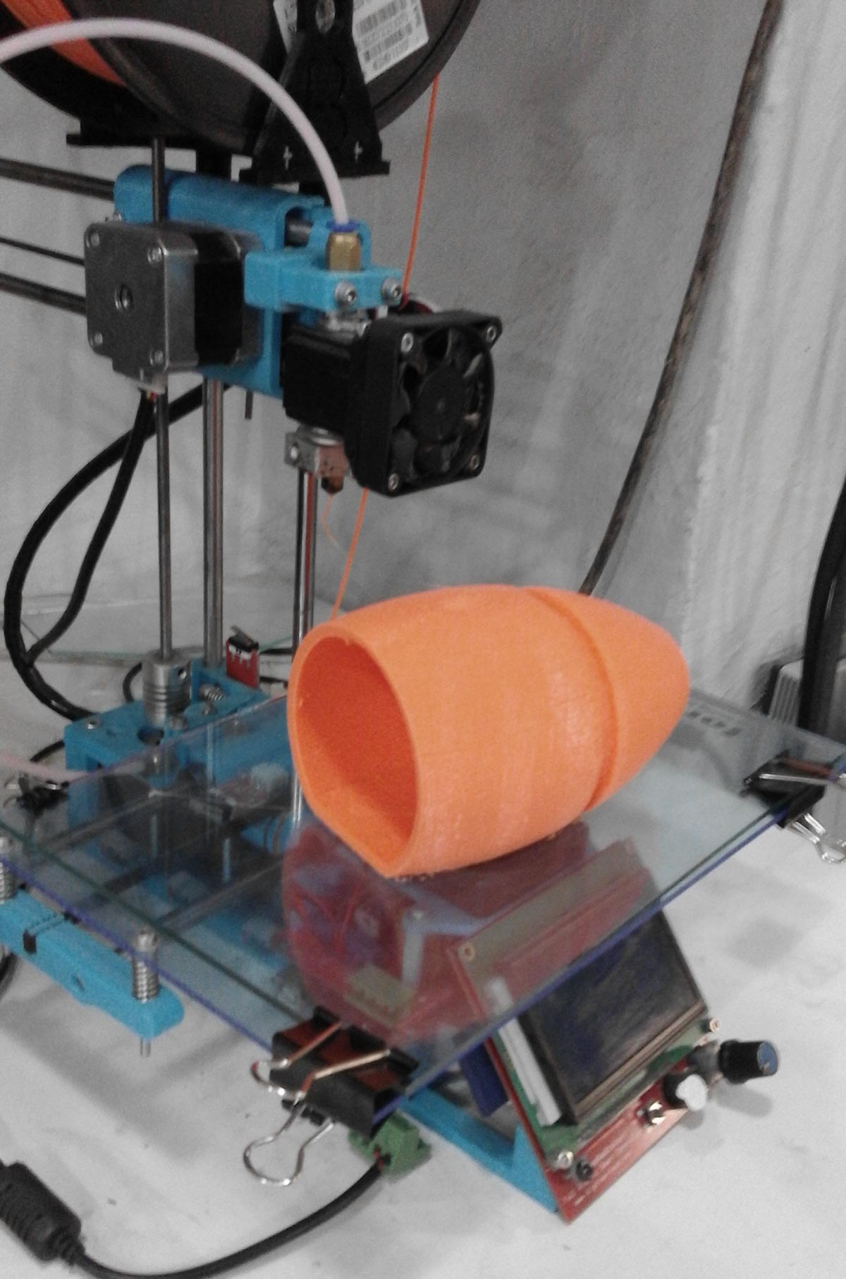
Making large prints lead to a few disasters especially while printing over night. In this case we found out that the heat bed stopped working; making the print curl up and extrude into a pla "ball". The printer was slowly taken off with plyers and brought back to new after a day; Ooce reprap broken parts were reprinted and extruder unblocked by heating and using a fine wire from below.
Thus resolving in doing things part by part; can have its benefits.. This was later modified into a design which could allow easy modification should the pipe need to be changed for example.
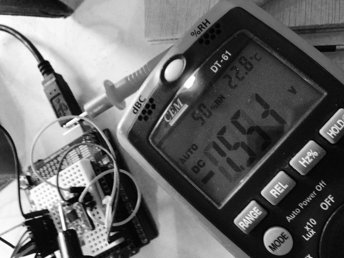
As the mechanics of this was more complex than expected i used easy driver with arduino like the following tutorial by schmalzhaus
To increase the voltage of the stepper; simply rotate the 'screw' on the driver and read voltage between it and the usb cable.
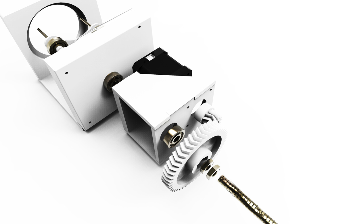
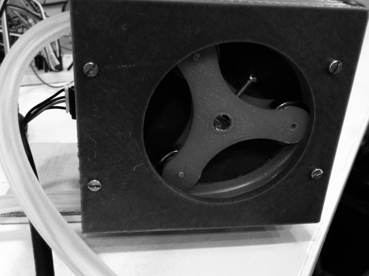
Version three was designed in a way to allow a lot of interchangeablity should something need arranging. I increased the number of ball bearings to squash the pipe but created less pipe squashing length. Occlusion (which refers to how much squeezing is happening to the tubes) could be adjusted by 3d printing one part and in fact this worked on the second try of approc .25 mm.
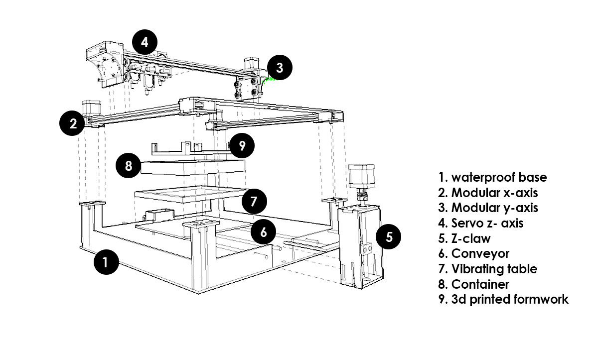
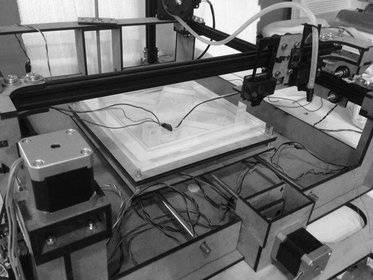
At a later date i decided to develop the machine into xy v slot sytem. I developed the design in rhino3d using Openbuild blocks as blocks and reference.
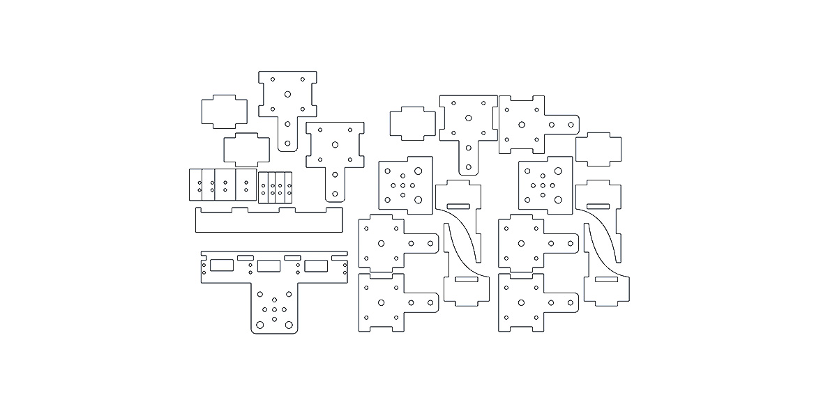
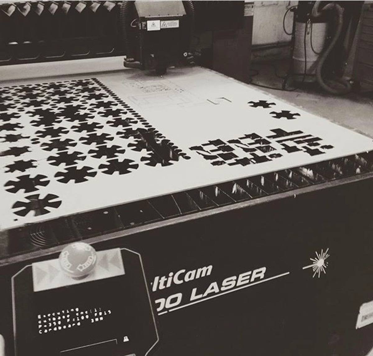
converting 3d to 2d laser cut files; as it tends to be to fastest way to fabricate in the lab; also very durable with acrylic or mdf (however mdf is only suggested for prototypes as will wear and tear quickly)
Make sure pressfit is tight and use some glue only where necessary; for additional strength.
Assembling everything together considering all screws; washers and bolts as well as electronics and motors. Base was used to hide all electronics.
Bill of quantities:
Although everything adds up into such a pricel this machine was actually build from recycled parts taken from a reprap and items found in the lab. Therefore reducing the price and 'recycling'.
hydrobot by joegalea on Sketchfab
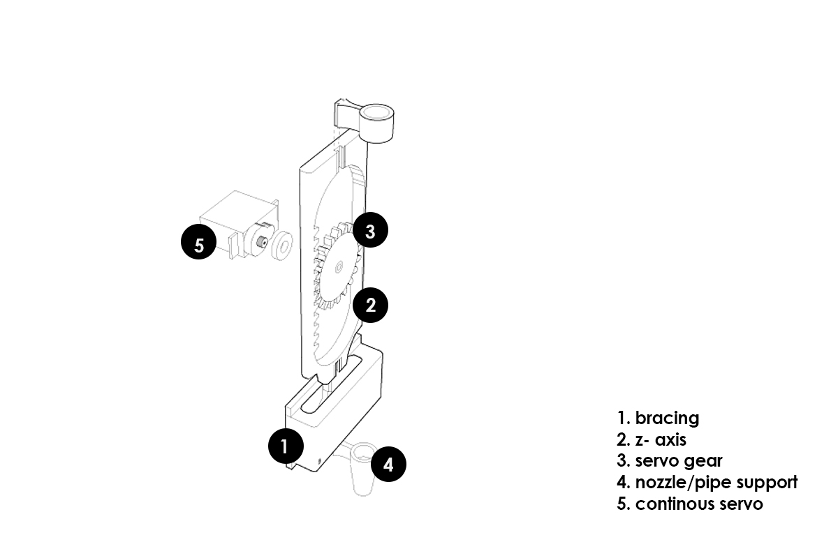
Servos are being used as a z axis to evetually acts as a possible valvue should the pump not be necessary for certain materials but also as a z movement for closer reach when filling the space.