Final | PROJECT

I'm passionated about astronomy and astrophotography.
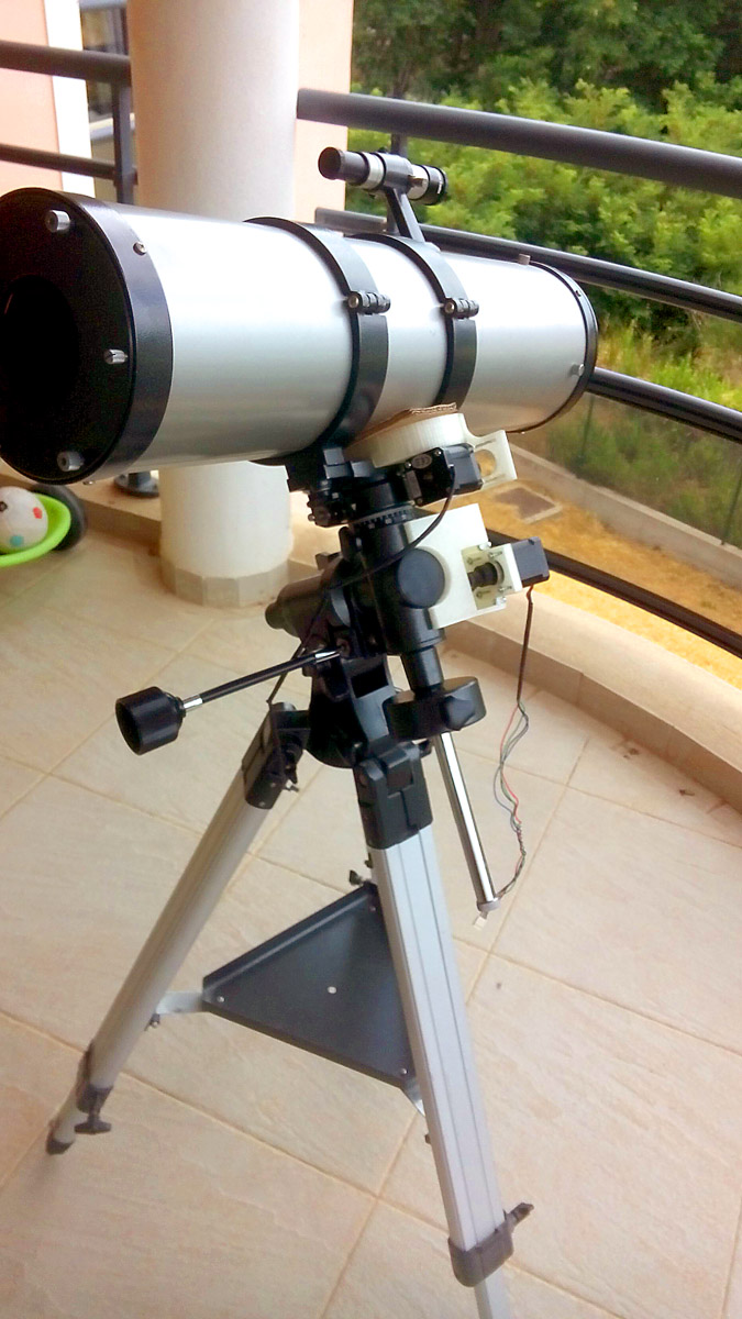
when I was 17 or 18 years old, I bought a telescope (a Orion Skyview - seems too old to be found on Internet), I've got one of the cheapest available. No motors, no intelligence, only a old school telescope, and it was perfect for me.
Today, I don't use it at all, for further reasons, but mainly because I lack time, and aligning the telescope is time consuming, because we need to precisely align one of the axis (the polar axis) with the astronomic north pole, this is an iterative process wich may take up to one hour, and the precision of this alignment is critical for a good operating telescope, specially for astro-photography
So, I decided to take my old equatorial mount (a Orion Skyview Deluxe EQ), and adding some vitamins and intelligence in here !
Commercial kits exists, but they are quite expensive (further hundred euros), buying one is not a solution for me.
Here is what I plan to do (the begining of the Spiral developpment) :
- Making some mount to fix 2 stepper motors
with shaft encoders, one for each axis - Adding a microcontroler to drive the motors, and handle communication with a PC or a to-be-made simple hand controler
- Try to make all the parts modular, so they can be adapted on other mounts brand, but this is not a critical goal
- Programming the microcontroler with a procedure to make alignment easier/faster
- Adding some sensors (like 3 axis accelerometer, GPS or compass) to make aligning more faster/easier/automatized
- Make a smarter handled controler, so I don't need to use a PC, or
- Code a mobile app to use as a hand controller
All those mods would be done without modifying the equatorial mount itself, for a very simple reason : if I fail (and it's probably sure I'll fail somewhere), I want the mount to still be usable.
In case this project isn't eligible, I still have a B-plan which consists to create a motorized and remotely controlled camera jig placed under a transparent dome, placed on the roof of a car, to take thunderstorm photographies while I'm safely and comfortably installed in the car. :)
TLDR;
Here is the video presentation of the final project working
Build log
I separated this build log by categories and sub categories (mechanic, electronic, code...). Each (sub)category was fullfilled while working on the project. It's for this reason that, sometime, sentences was falsely deleted, it's a way to keep track of what's going on.
You can find source files here :
- CAD Source files (FreeCAD)
- STL files
- PCB source files (KiCAD) and all boards traces/drill/outline (PNG)
- Code source files
- SVG Keypad schematic, board
- SVG motor board schematic, board
1. Mechanical side
Sketches
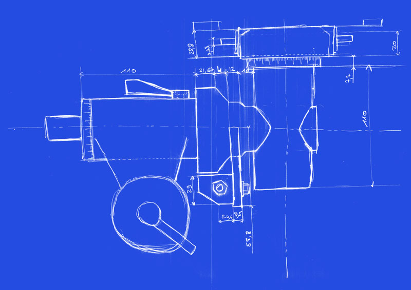
Here are bluprints of the mount (without its legs, units are in millimeters) and a sketch of what I want to do on it :
Front view :
Top view :
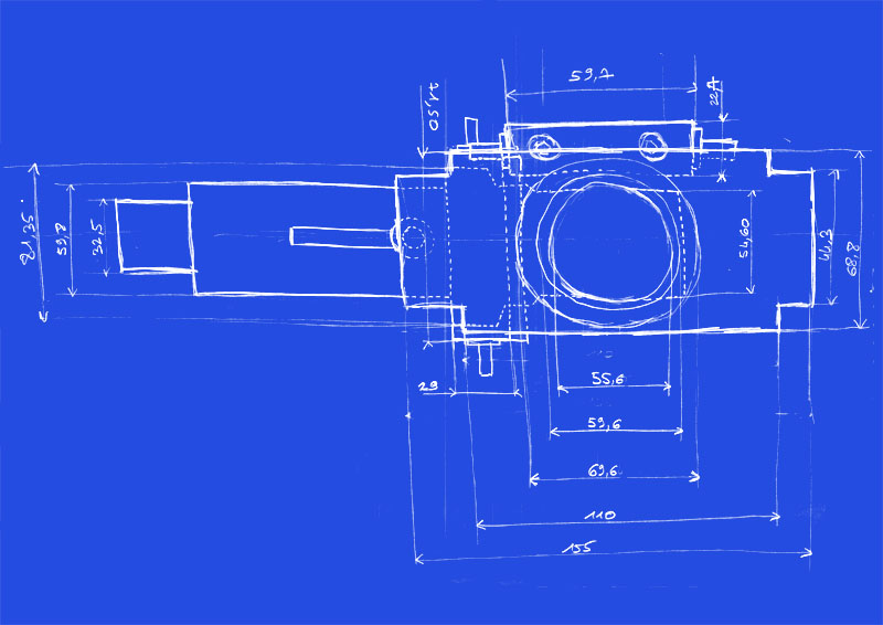
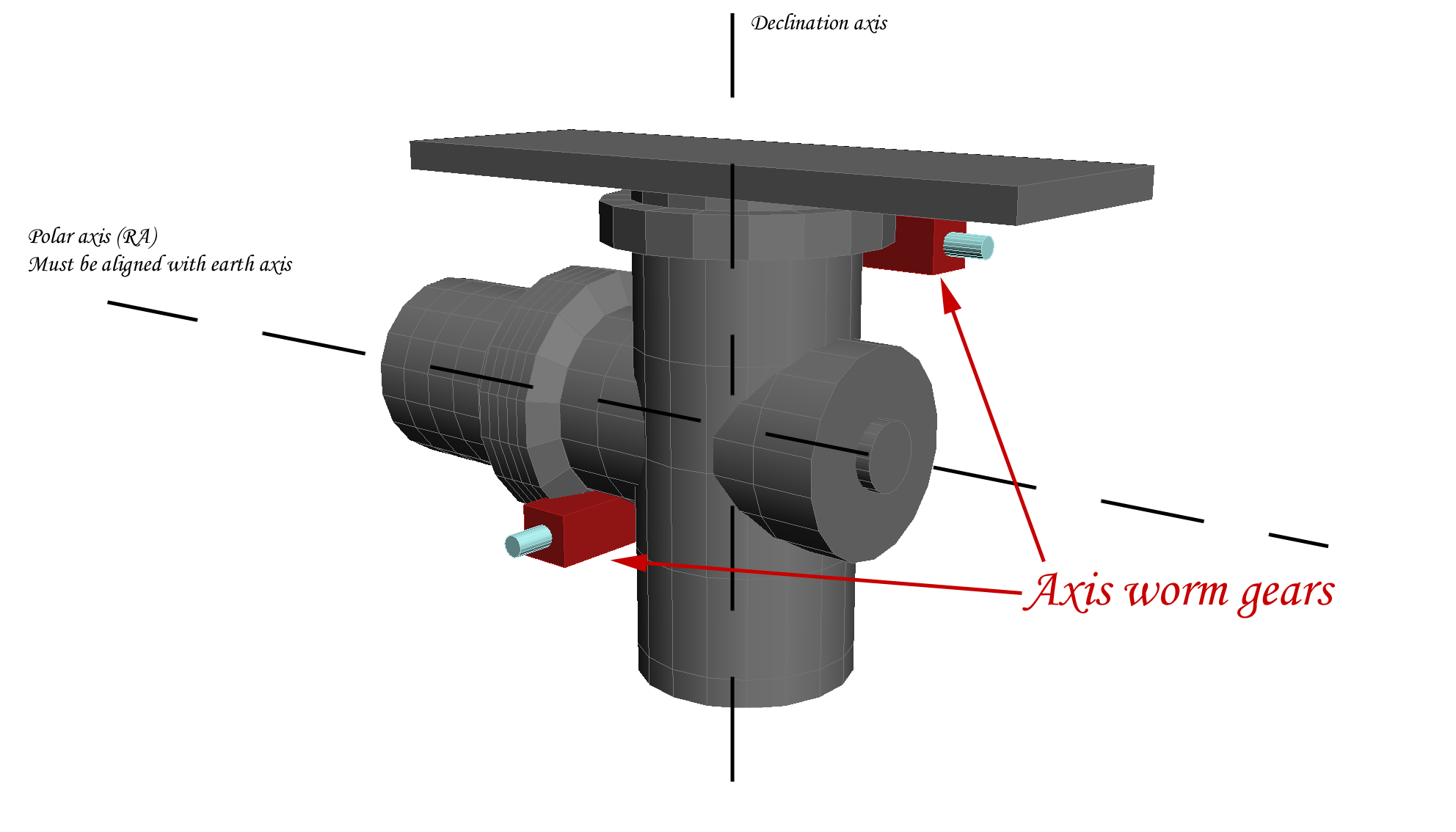
The two red parts are the wormgears that moves both axis (Polar and Declination), there are a metalic pin passing thru the blocks, where we can fix some handles to operate the axis.
I must admit one thing, I lied above, when I said that the mount was shipped without motors. There was one DC motor, that could be fixed on a metalic pin available on the side of the mount, with the shaft fixed on the bottom wormgear. This cheap DC motor allow the (correctly aligned) mount to follow the earth rotation, avoiding the beautiful stars to drift away in the occular.
Anyway, this motor was just running "as is", without any loop-control of any kind, with the speed directly depending upon the health of a few 1.5V batteries. Cheap, as I said.
Motor holders
The idea is to make two motor holders wich would be fixed either on the red parts (they are fixed with fasteners), or directly on the axis, and then bind the motor shafts on the wormgear pins.
There are pros and cons for both fixature :
- Fixing on the wormgear block would make the mod more robust but will make portability on another mount brand more difficult
- Fixing on the axis mould make it more adaptable, but with more risk of drift or backslashes
The choosen ones
Finally, I choosed another way than the one listed above. I make a 3D printed part (for now) containing the motors, and witch will be fixed on the existing metallic pin AND use the axis to stay steady.
I still have to print and test this part, but basically that's the way I'll go for fixing the motors.
I run thru few iteration to obtain a part with good dimensions and witch will correctly fit my mount.
 This was the first iteration, dimensions was almost good but the part didn't fit
 2nd iteration, dimensions was OK but, because was not seen because of the mis-fit of the first try.
 3rd iteration - not printed (I changed the design just before - see iteration 4.)
 4th iteration.
For the fourth (and in theory last) iteration, I changed the design to fix the motor from the front instead of the rear, it's more practical but require more material to print the part.
To gain some time and waste less PLA, I sliced all those iteration with an almost empty infill (10%), using a great feature of Slic3r : "Infill only where needed" - but they still need 7~10 hours to be printed.
Parts are not usable as is, but this gives me a perfect preview of potential errors or misfit.

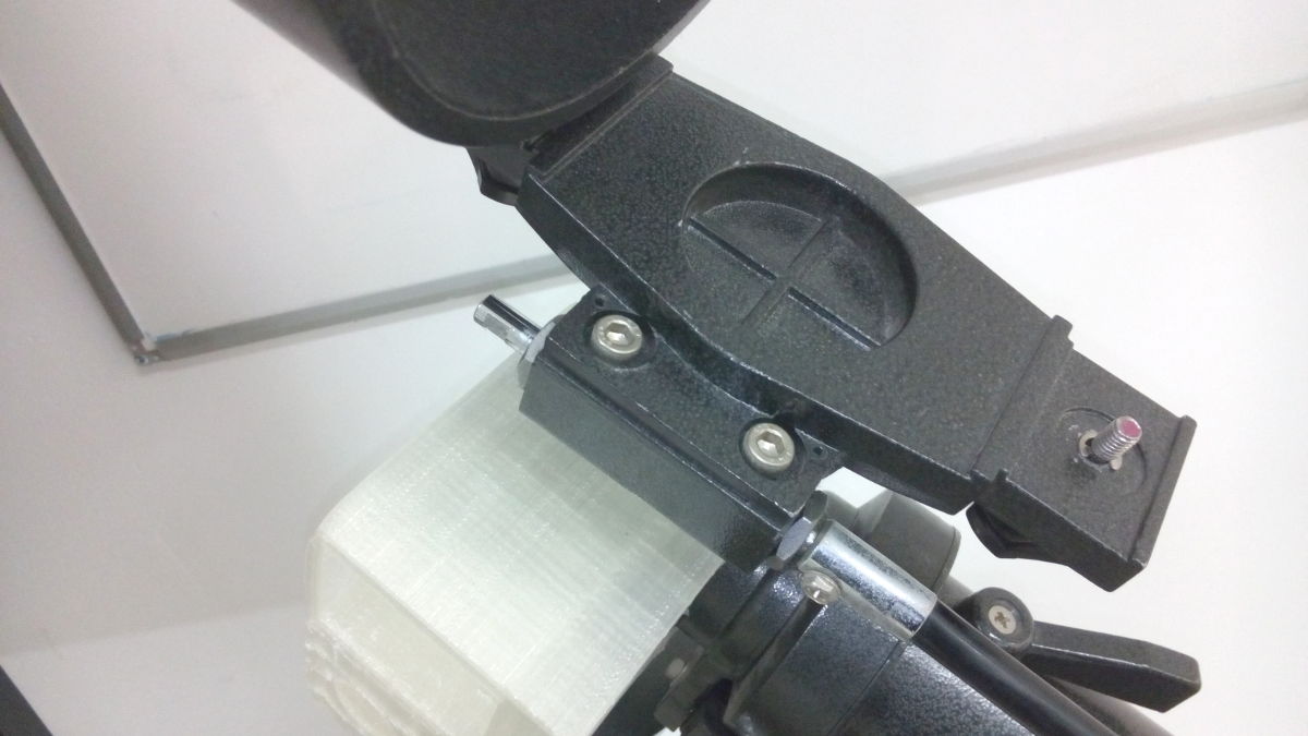
Here is how the motor holder should be fixed (we can not see the metal pin because it is in the hole).
Note: for the final part, I will certainly use ABS instead of PLA, because the motors could run hot on long-time use
HUGE mistake
Well, until now, all the mistakes I made was not very critical, but this one it THE one.
The motor attachement part I designed for almost two weeks will works only for the pola axis, because...
Wait for it...
The Declination axis ROTATES independantly from the polar axis. So the motor of the declination axis, in the attachment fixed on the POLAR axis, will NOT follow the declination shaft as it rotates.
...
a LEGEN-DARY mistake.
Fixing the mess - Declination and Polar motor holders
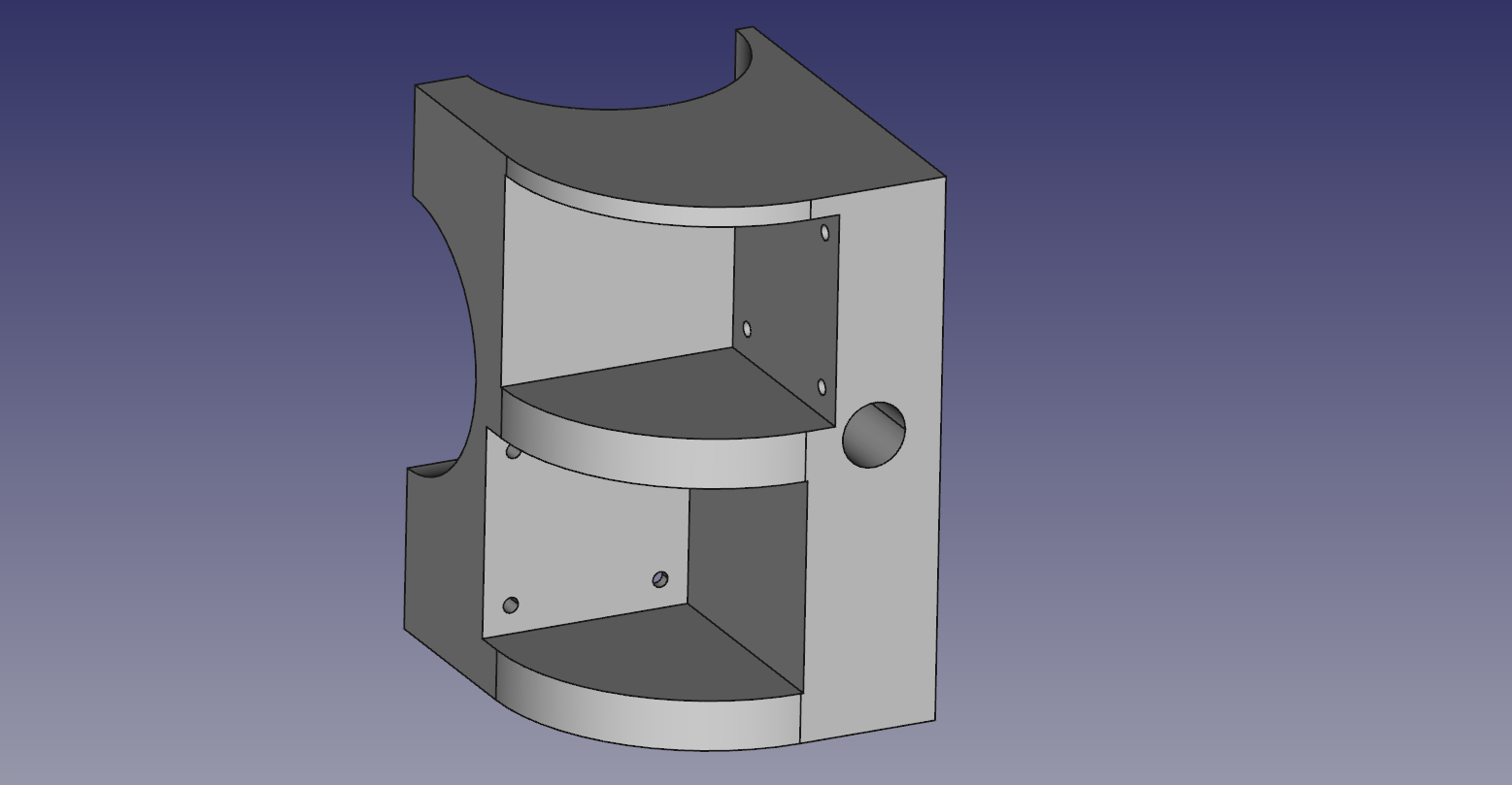
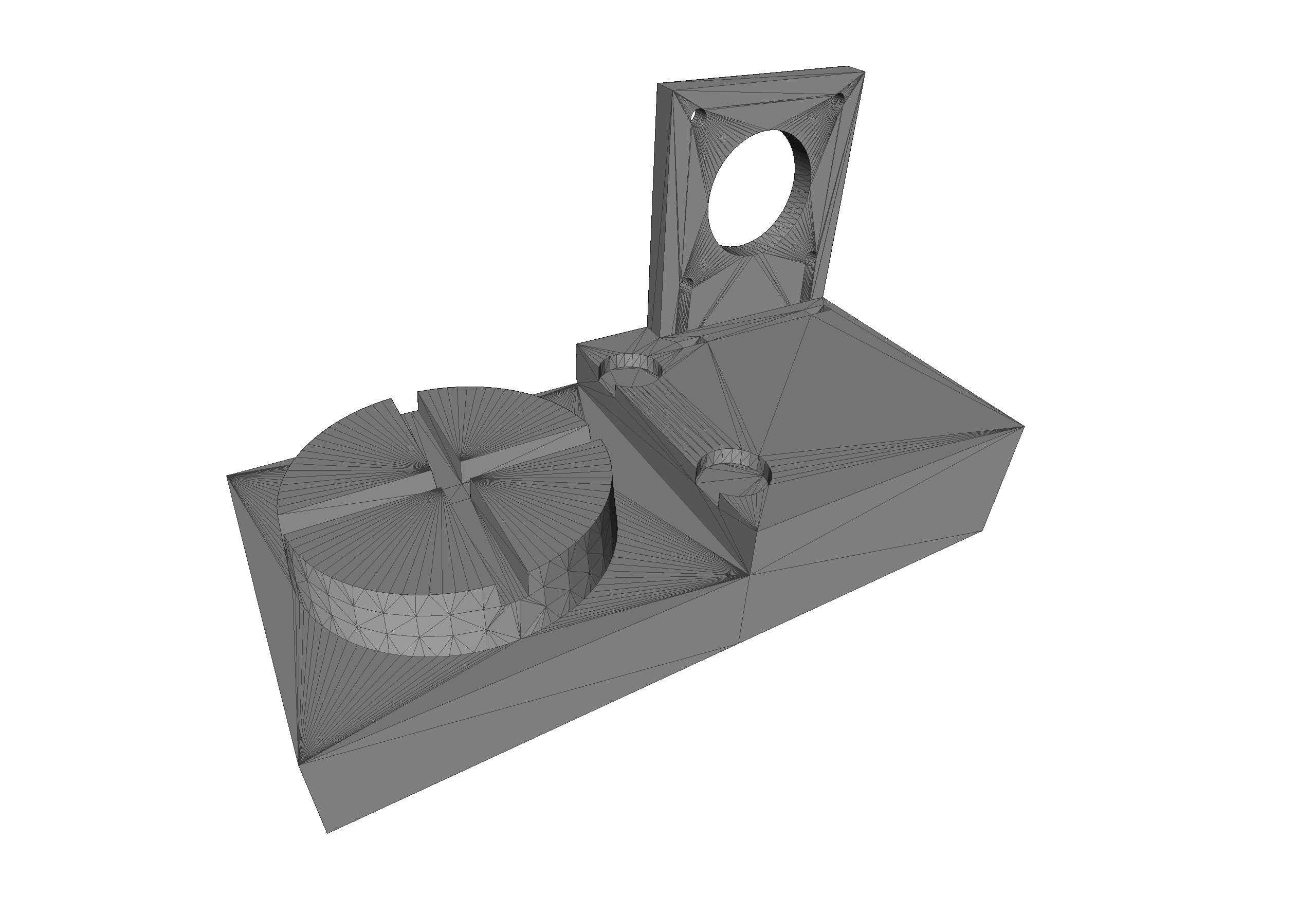
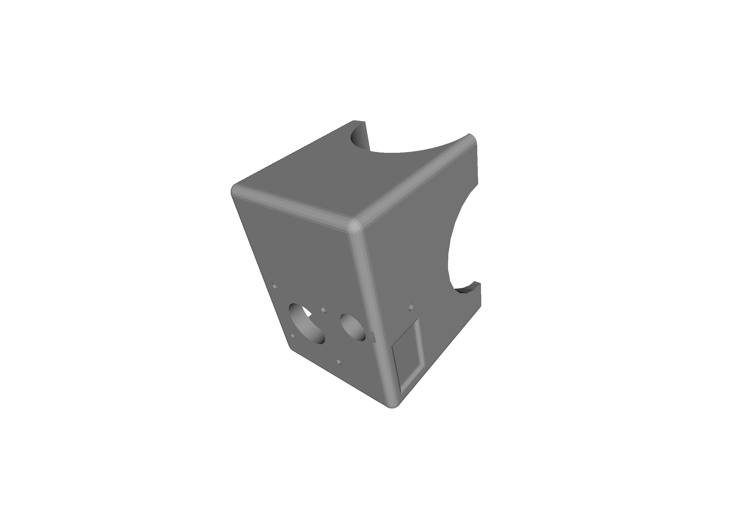 So here is how I have redesigned the part - the last iteration I hope.
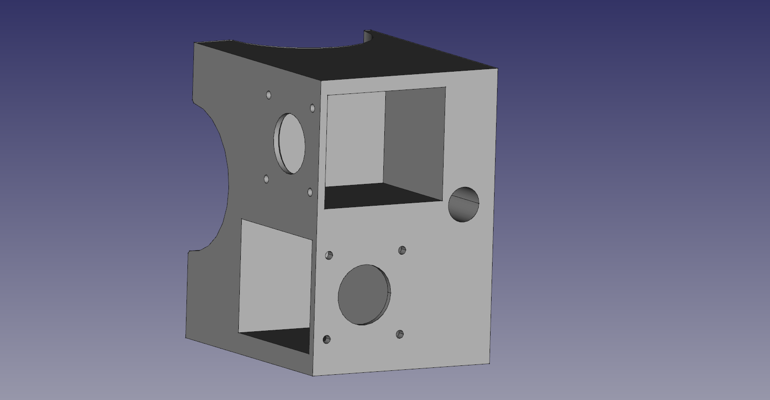
I have reduced the size (but not much), removed the useless motor pocket, and added a little window for the belt to pass thru (for alignement reason, the motor will be fixed on the outside). I also added 4 bigger holes on the back, to be able to actually use the screwdriver to fix the motor.
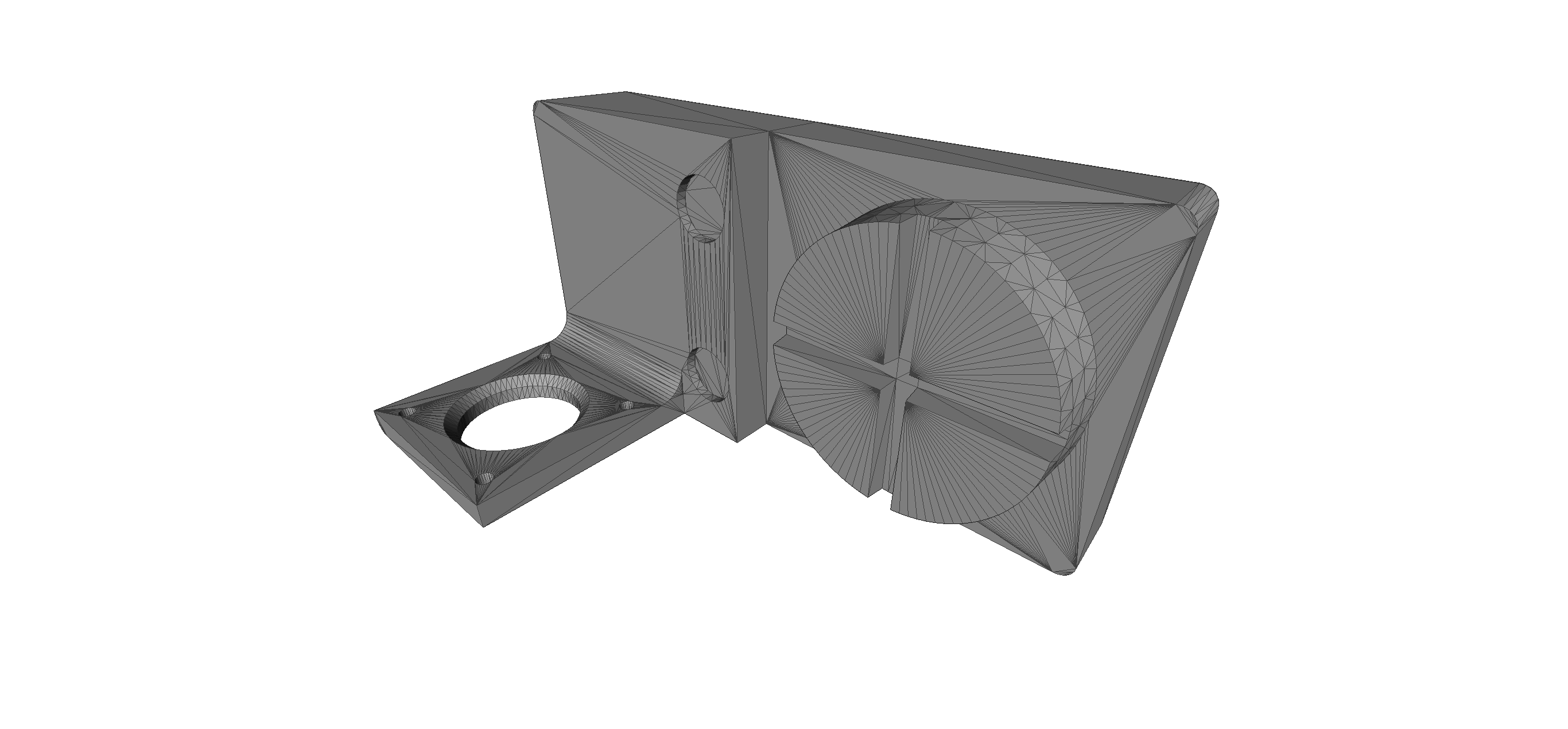
I also designed another attachment for the declination motor, it will be placed on the top of the telescope witch, fortunately, is machined in a way making easier the fixation of this part.
 After a rude battle with the 3D printer and a light redesign of the part to correctly print it, here we go (slightly delaminated part but still OK for test-fit)
 I also redesigned this part for two reason : better align two holes to avoid colision with two fasteners on the mount, and make the part that hold the motor amovible. This will allow for a more robust print, with an added benefit of an easier part exchange in case of problem (i.e. : only a little plate to re-print instead of the whole piece)
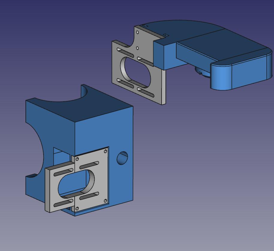
Yet another redesign
I was wrong, the two holders needed redesign because of belt issue
So on the declination holder (top right), I moved the motor on the opposite side to be able to use longer belt and, more importantly, larger toother pulley (on the last design, large pulley hits the motor).
I also moved the motor about 15mm ahead for an optimized alignement with the mount's shaft. In the same time, pocket for the motor fixation was made deeper - additionnal pieces could be printed to better align the motor without printing a whole new part.
The motor fixature was made longer and with slot instead of holes, this will allow me to slide the motor until the belt is tightened. Simple and reliable.
The polar motor holder has been redesigned in a similar way : a motor fixation plate (with slots) had been created with will be fixed on the holder
And finally, this is a working design. I just need to make the slots longer; but it should take some tens of minutes to be printed.
Pulleys
Ok, now that the holders design are pretty final, time to think about the transmission.I have thinked of a few methods :
- Direct drive using flexible couplers (Fab-made or aluminum) This method needs the motors to be perfectly aligned with the gearworms shafts. I think it's not reliable because it would introduce a big stress on the part where the motor is fixed. And I'm not sure the motor would have enough torque to move the whole thing directly
- Geared drive Would introduce backslash if gears are not perfectly made, as well as a lot of friction (and thus, noise)
- Toothed belts My favorite method : almost no noise, no backslash and belts can be tensionned using
I have the belts, I have the corresponding pulleys (some S2M ones) but unfortunatly, the pulleys didn't fit neither on the motors shaft, nor on the axis shaft...
First, I tried to drill the holes bigger (pulley inner hole was 5 or 6mm diameter, telescope shafts are ~7.5mm), but it didn't work because of the was the pulleys was made (a lot of empty space - certainly to save plastic on fabrication). I'm sorry, I didn't take pictures of that...
Motor shaft, on the opposite, have a smaller diameter (4mm). I first planned to use heatshrink tubing to make the shaft diameter bigger, but it'd would have introduced too many errors.
 So i decided to 3D print them using our Form1 printer.
I designed the first pulley in FreeCAD but at the middle of the work, I realized I was wasting my precious time, so instead I goes on thingiverse,
found this files,
raging about this crappy 3D Slash,
found this others files,
installed openscad
and after tweaking some variables, voilà !
And here are the results :
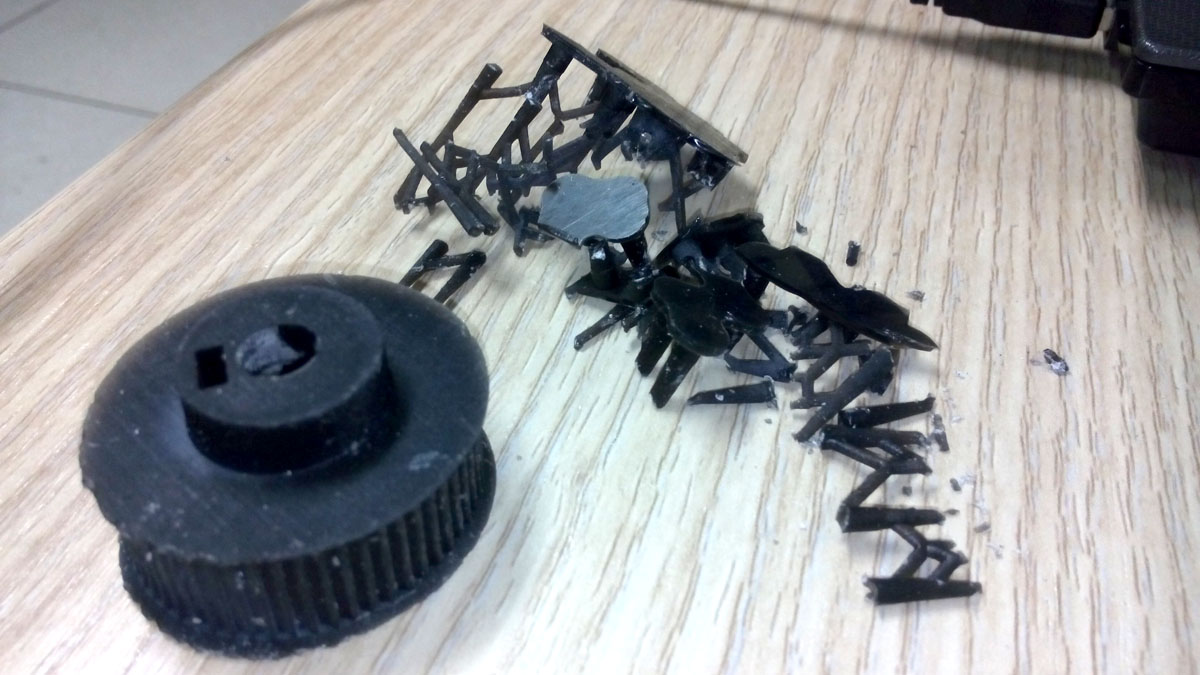

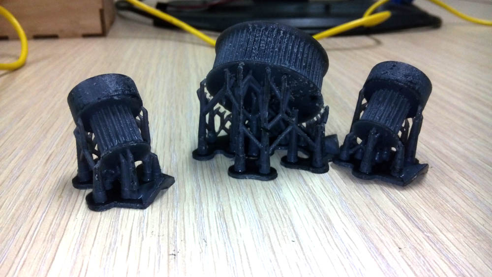
It took me about 4 hours (printing time included) but I saved a few euros by not buying aluminium machined pulleys
The pulleys was perfect, but unfortunately the toothed belts I've salvaged some month ago are too tight. I printed another set of two "big" pulleys (40 tooth instead of 60), but then the belt was way too lose. I had to find a way to tighten the belt (using a spring or something like that).
Giving up on the belt tensioner
I waste a lot of time by trying to tension the belts using smooth pulleys (3D printed with the Form1 too). The problem is that either the belt was too loose, or way too thighten. I ran out of time, so after a little break to cool down nerves & neurons, I came up with what I think should be the way to do : re-re-re-re-designing the holders.
Motor board box
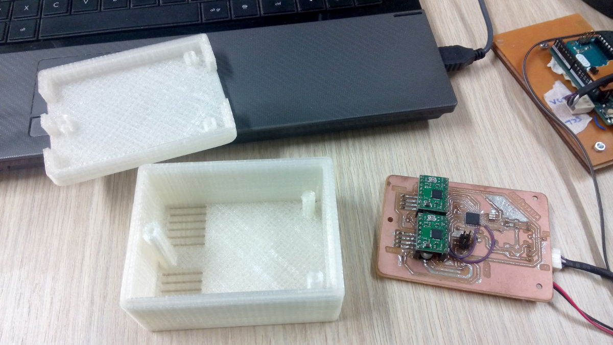
 I designed a "little" box for the motor board, witch should be fixed on the RA motor holder. This is to protect the board from a to high humidity. The board will be fixed on the top side of the box, with three screws to close the box and fix the board at the same time.
I made some vents to cool down the drivers.
I made this board when iteration 4 of the motor holder was thought to be the good one, so now, because almost all of the dimensions have changed, this box needs to be fixed somewhere else.
Top part of this box also needs to be made deeper because of the proheminent headers I used for the connection. But it's not critic for now
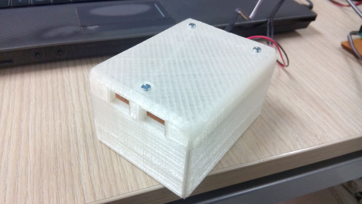
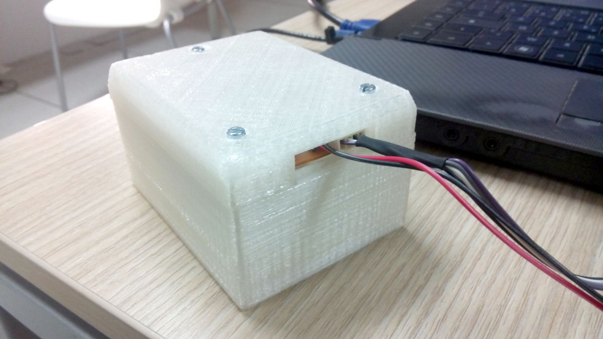
Here are pictures of the final box. On one side, there are the I²C connector and the motor's power supply, on the opposite side there are the two connectors for the steppers
I printed the box with a little border all around, to do some press-fit. I also added some vent in the bottom to ease the cooling of the drivers. But I will need to add a small fan and/or good heatsink on the chip because they are overheating after some minutes of use.
Hand controller enclosure
The hand controller enclosure have been made to avoid a big mess of wires. Initially, I wanted to 3D print all the part of the enclosure, but finally I choosed to 3D print only the bottom, and use the laser cutting machine to cut a piece of acrylic as the top part.
I love seeing what's inside a device

Here is the 3D printed prototype of the hand controller. Unfortunately, my printer cannot print this part at its original size, so I scaled it down of about 20 percent in the slic3r. That was an error. The part was then to tiny for the arduino + keypad + lcd + cables to fit inside.
So instead of re-print the part in the Fablab, I made the lasercutted hand controller.
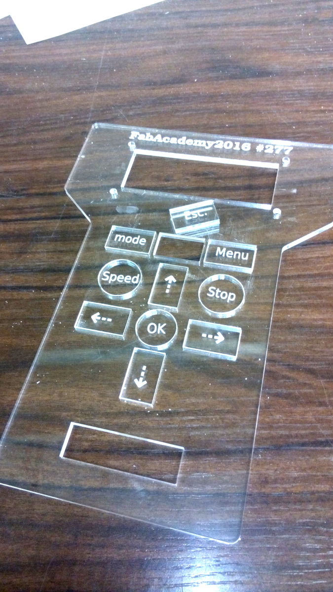
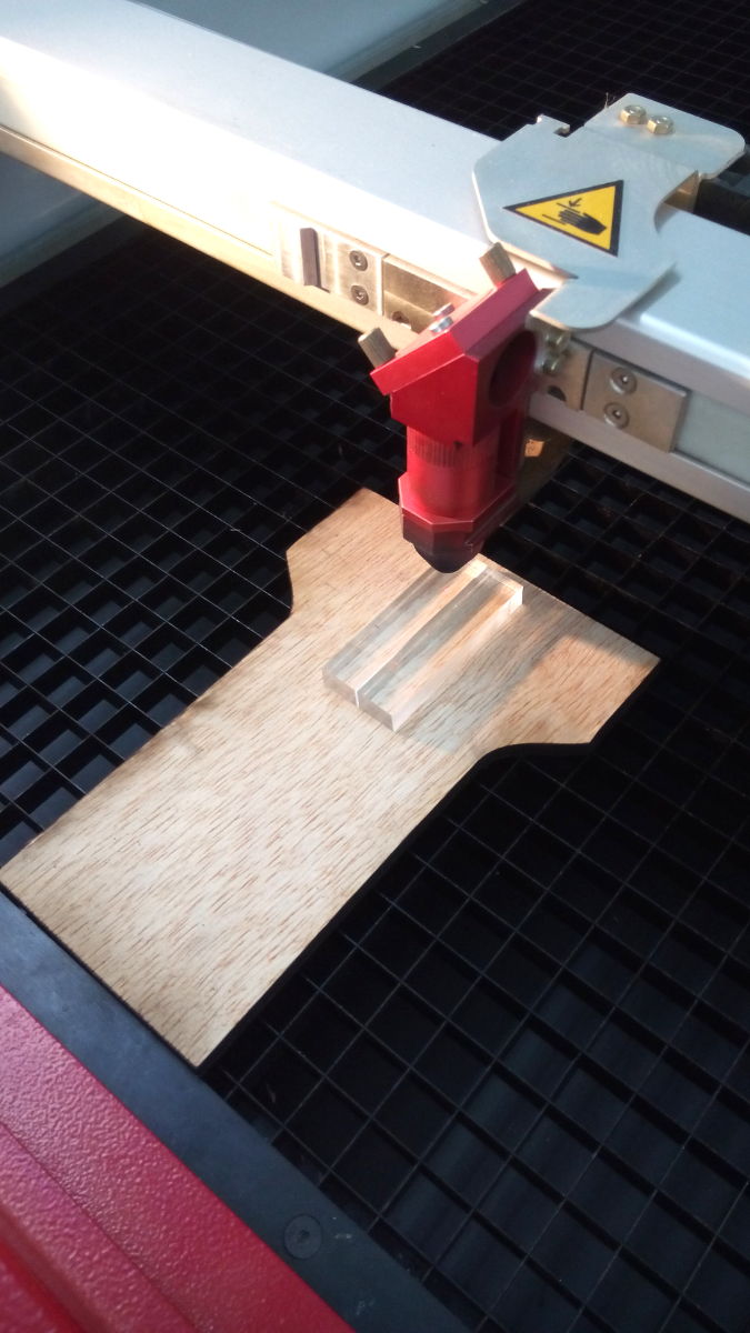
This is the top of the hand controller. It's made with 3mm thick clear acrylic, button have been engraved and stored for later use. I plan to use a transparent sticker to fix the buttons in place, but my first trys was disapointing. So for now, I simply push the button thru the holes.

Those are "layers" of the hand controller made in 5mm thick plywood. To save material, I cutted less layers than needed... I had a plan.
Not shown in the picture is the base plate. Same shape but without the cutoff inside
Those are two scrap pieces of 1cm thick clear acrylic, witch were cutted in a lot of 5mm little inserts. Those jigs was glued between the layers of plywood to make the hand controller deeper without using too much material.
They are placed on top of a scrap piece of plywood to avoid them to fall under the grid of the laser cutter. It was convenient, but on some spot, the laser was powerfull enough to burn the wood (but without passing thru it), that's why some insert have this brownish color
This is the final result. Boards and cables are properly packaged (even if, I agree, this packaging is not looking sexy).
Top plate is fixed using double side tape, all layers and acrylic inserts are glued using wood glue.
Keypad and LCD are fixed using nuts and screws on the top plate
We can see the yellow USB cable for the Arduino, and I²C cable going to the motor board (witch I should make a little longer to be more convenient)
We all agreed that this hand controller enclosure needs a better design, but it's a working prototype and for now, I'm OK with that.
Semi-Final result
 Here are the motors mounted in their respective holders.
At first, I wanted to use ABS (in blue), but the print goes wrong with the RA motor holder (all layers stripped off), certainly something wrong with temperature. There is the same problem on the declination motor holder, but the part is still good for use.
Anticipating this trouble, I printed another RA motor holder with my own printer, using PLA, and it's OK.
The only problem I could have is the PLA melting because of the motor's temperature rise in use. Wait and See.
I'll certainly do another ABS print later, but right now lets focus on more critical things.
On this picture, belt and motor board box are missing.
Title says "Semi final result" because this was tought to be the good design.
In fact, this was working. But I failed to easily tension the belt, so I gone with a redesign
Final assembly (but still prototype)

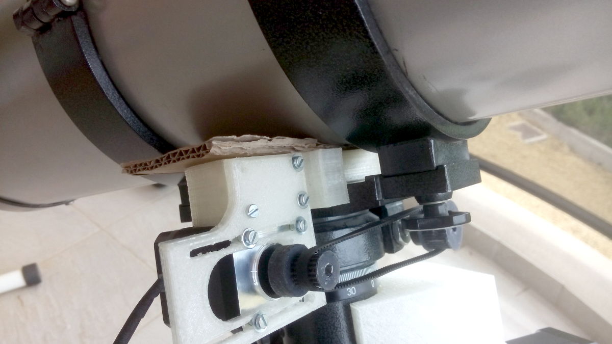 The two pictures above shows the two motor holders, with motor, pulleys and belt in place. This is the working design. Notice the piece of cardboard between the tube and the declination motor holder. It's there to maintain a pressure on the holder so it will not drift out while in use because the tube is strongly fixed. A piece of foam would be better but that's all I had on hand, and it work fine.
Unfortunately, the pulley on the polar motor brokes up on the first run :

It's my fault, I tightened the screw a bit too hardly.
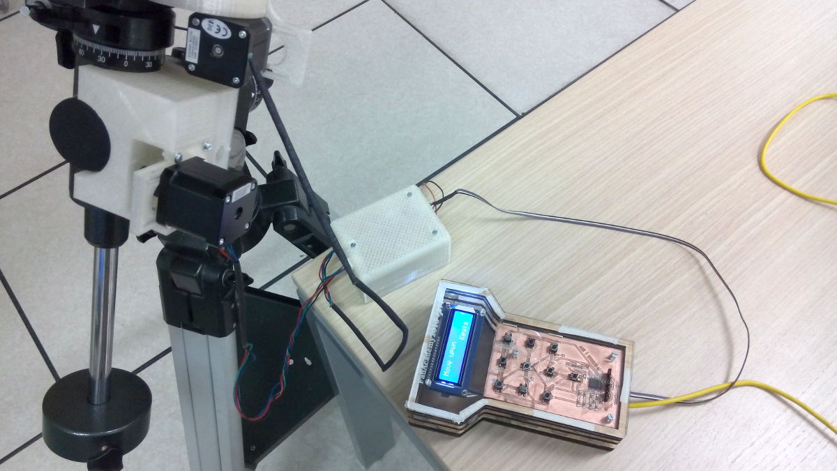
And finally, final assembly with all the packaging (no naked boards or floating wires, except the one going to/from the motor board and the hand controller)
2. Electronic side

For the electronic, I choose to use... wait for it... an Arduino ! (or at least an Atmel MCU based board)
Instead of simply use an arduino with shields, I think I will design a board(s) witch will contain everything needed.
There will be a main board, witch will be in charge of communication (With a computer), display (on a LCD), reading a home-made keypad and control the motors.
This main board will certainly be the handheld controller, and it will not control the motors directly but instead, I plan to use another "daugher" board witch will control the motors.
The Week 13 assignement is the base for that daugher board, that will be reused for the final project.
As I choosed to use I²C to communicate with all the component, my idea is to make this daugher board communicate using this protocol as well and Week 15 will be the week I'll make this communication to work, so she will embed a MCU and receive commands from the main board (in a still-to-be-defined format) and run the motors according to the commands. This will unload the main board for the steps, acceleration and timing stuff of the motors
And because I use I²C, I can happily forget a RTC Clock in the design phase, without losing my hairs because I need to redraw all my boards. Just plug an I²C RTC Clock, implement the code and go on (finally, instead of buying an already made breakout, I'll made my own)
For the Week16, we had to make communication between a host and a microcontroler, So I did an analyze of the source code of Stellarium and of the Meade's LX200 Protocol and began to code
It's not yet finished, but I got some success (and some trouble too)
Keypad
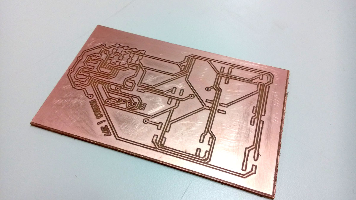
Since the begining, I wanted to make a keypad (based on thing like that)
Unfortunately, there was a mistake made when ordering the PCF8574 I²C port expander chip, another chip was ordered instead, totally useless for this application (it was an Analog demux if I remember). The instructor did another order, but we are still waiting for shipping.
I will solder the components when the chip will arrive.
Components just arrived so here is the complete board :
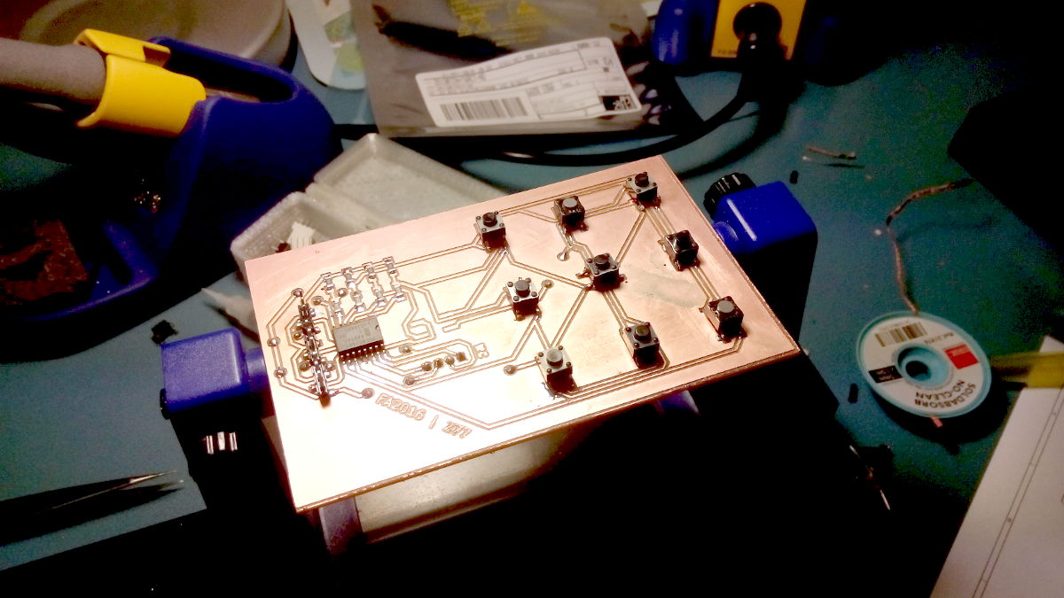
Sad that two of the push buttons are not/erratically working (the two with grey caps) - hey, that's the game when salvaging components.
LCD
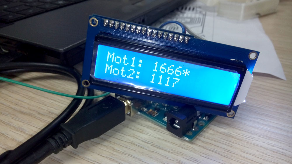
A little LCD is usefull for this project, but they require a lot of pin from the microcontroller to work. So I decided to buy a LCD I²C/SPI Backpack from Adafruit along with a 2 lines LCD module.
Adafruit gives a pretty good and easy to use librairy and I already managed to display some infos. Right now, it is used like a way to debug things, but later it will shows usefull informations (like name of the target, speed or DEC/RA values, etc...)
Cables
 Because most of my modules will communicate with I²C protocol, I needed cables to connect them together. I found a webpage describing what seems to be the official connector pinout, so I started with that as a base and wired all my boards using this pinout.
Unfortunately, I forgot to make those board daisychainable, so they only have one connector. Thats why I needed to make some cables especially for this.
I already have pins and housing to make connectors, so I used ribbon cable and a crimp tool (thanks to Frithjof) and patience to make dual-four-wires connectors
I had to make sure the cable will be long enough to connect the hand controller and the motor board (witch will be fixed on the mount)
Arduino connection shield

To ease the connection between the different boards, I made a little arduino almost-shield witch only contains two connectors for I²C, two pullup resistors and a jumper for enabling them.
This little shield is not full-width, this serves two goals : does not take too long to mill, and saves material. I used adjacent arduino pins as mounting points even if they are not used by the shield.
My apologies for the bad picture quality, but it turns out that I had only this photo of the shield and at the time I'm writing this, the shield is in a box at home.
Motor board
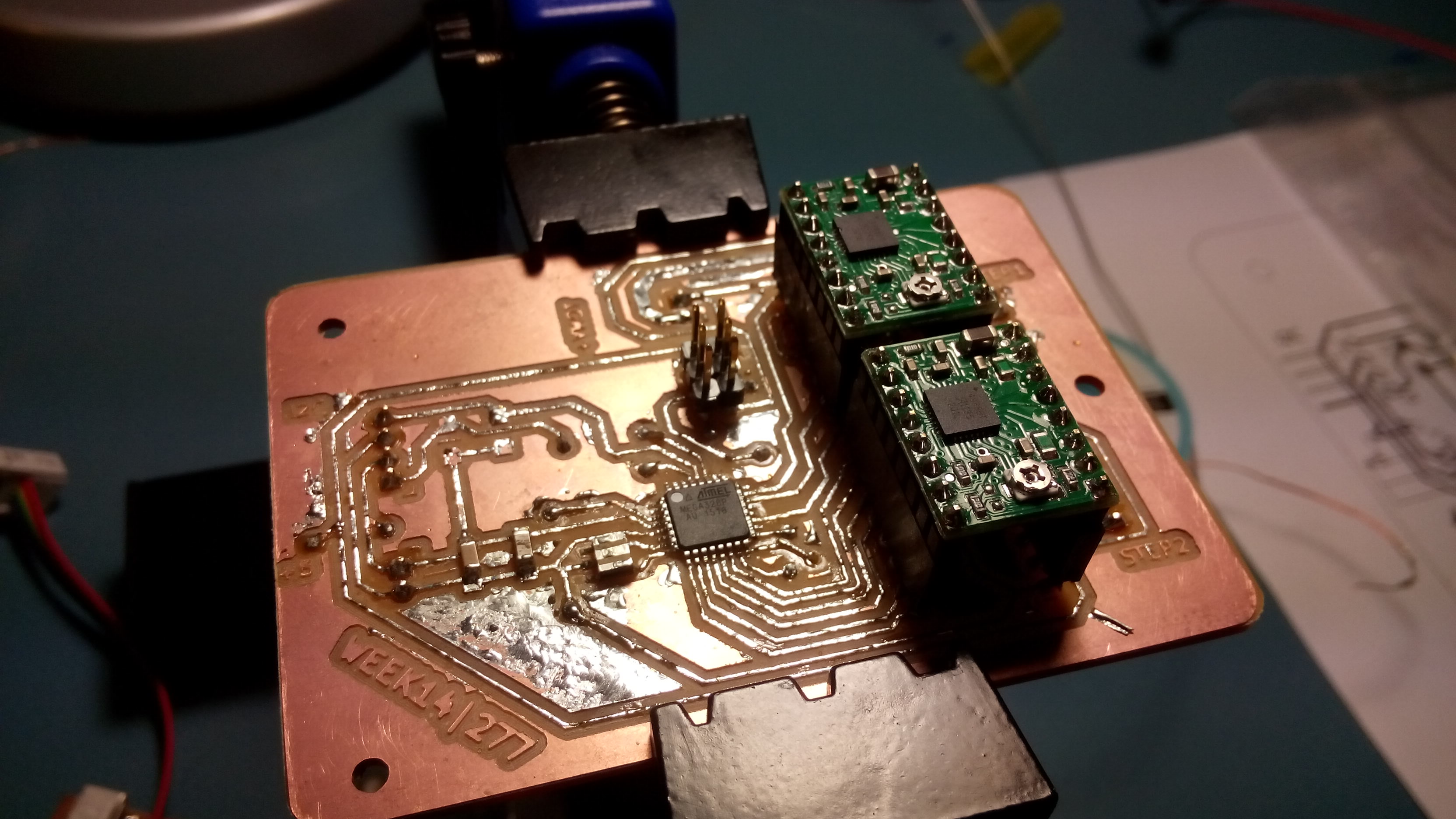
This is the motor board made on Week 15, I will let you look this page for more infos.
The board work really fine, even if programming her need to be done under Windows using Arduino IDE, it doesn't work on linux with Arduino-mk. I think (but not sure) it's due to a different version of GCC being used, or at least different optimizations.
Even if this board is working fine, there is a little problem anyway. Stepper drivers (two pololu A4988) are running hot quickly (about 10 sec. of continuous rotation of the motor).
This cause the stepper driver to enter in safe mode for a second every pair of seconds. Two little heatsinks would help but I didn't have them yet.
I could also cut a chipset heatsink with a saw, it would work.
Assemble !

So, right now, I have two boards made on weeks 6 and 15, a foetus of hand-controller unit designed in week 3, the keypad, motor attachment made between two exercises and tinkering on the code made since week 15... Slow but effective progress, I just need to clean all that and put it together.
Unfortunetly, it seems that my "main" board, made in week 6 as a few design flaws :
- Bad I²C pinout used
- SMD headers instead of thru-holes (fragile connexions)
- Randomly placed headers (hard to connect)
Those flaws are not critical, but actually, I uploaded a known-to-work code on this board (tested on an Arduino before), and nothing was working - still need to investigate but time is running out.
So that's why I will use an Arduino as the main board for now - other boards are still the ones made during the weeks exercises.
So, with all the board finally made, I wired them all using my cable, and begin some tests
Note : As you can see, the little connection shield is missing, I didn't made him yet when I took this picture
3. Coding
Code is my nemesis for this project. I totally under-estimted the difficulty of the mathematics stuff.
Right now, I have only made the different boards to communicate together (witch is a good thing), but I still need to make a proper code, managing a menu to be displayed on the LCD, managing all the calculations between equatorial coordinates, conversion in motor steps, and so on...
So, I applied the spiral method for coding too : as soon as a board was completed, I written some code to test her. I ended up with a few snippets of code for motors, I²C communication, Keypad, etc... that I just had to assemble in the same project.
And now, unlike for the Week15, I succeeded to make the Arduino makefile to work, so I can code under linux without the need for the Arduino IDE (but still need the Arduino core files because yeah, making I²C comms, stepper (A|DE)cceleration and things like that in pure C would take too much time).
The problem was some mistakes in the initial fullfilling of the local Makefile (wrong paths, mainly)
So, now, I write arduino code like always and just type "make" or "make upload" or "make ispload" depending on what I want to do
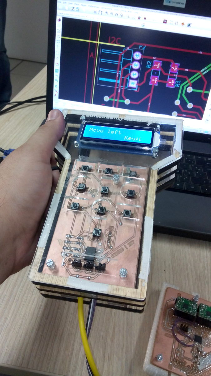
In this picture, we can see the Arduino, the LCD + LCD Backpack and my keypad board. The motor board is not wired because the lab power supply was not available at this time.
For testing purpose, the code sends random steps to the not-connected motor board, display them on the LCD screen, and as soon as I press a button on the keypad, the letter assigned to him shows up on the screen.
I had to make a little modification to the keypad library, so it sends a burst of letter when I keep a button pressed instead of only one letter. Basically, I just make the code react to a keyDown instead of keyUp.
This will allow me to keep - say - right arrow pressed, so the telescope will turn right continuously until I release the key.
For now, this code is very ugly and full of bug - but it seems to work.
I²C Communication
Motor board
The key part of this project is I²C, it's the spinal cord of all the boards. It was the key feature of the motorboard (and the keypad in another way) from the begining.
For this project, I made a little protocol using I²C, mainly for the main board and the motor board to communicate. I used a C structure to define some variables (type of command, speed, steps, etc...)
Here is a document (created during week 15) witch resume the different commands and values
Not all those commands are implemented in my code for now, but this document will be used as a reference.
To be able to send those datas on I²C bus, I used a C structures and a union
The union was needed to be able to send a given packets of bytes via the I²C bus. Sending directly the structure is not allowed, on the slave side, each received byte is then rearranged in the structure (using bit shift operators), and can then be accessed normally
 // exemple of reassembling with a LONG INT variable (four bytes)
    datas->distance =  (unsigned long)(receivedCommands[9] << 24);
    datas->distance |= (unsigned long)(receivedCommands[8] << 16);
    datas->distance |= (unsigned long)(receivedCommands[7] << 8);
    datas->distance |= (unsigned long)receivedCommands[6];
I still need to add some basic error check in the I²C frame to avoid / detect data corruption.
Reading the keypad
At first, the keypad didn't seem to function.
After some research, it appears that I was using a bad I²C address (0x70 instead of 0x38). The datasheet didn't say much about addressing of the PCF8574, so at first, I supposed that a floating address pin was pulled to ground - well, that's false.
To be sure, I uploaded an i2cscan sketch and boom! the keypad appeared with the good address on the Serial monitor.
In my main loop (on the main board), I do a regular poll of the keypad, as soon as a button is pushed, I take an action (stop/move the motors, set the speed, etc...).
I choose to use polling instead of interruption mainly to only use I²C connexion, using an interrupt means that I would have need to add a wire between the two boards. I choosed to use more MCU cycles instead of an additionnal wire (there are already so much ones into the hand controller...)
I use the library available into the arduino playground with some little modification (configuration was adapted to my custom keypad, and a little bit of code was changed to add support for long key presses)
Using the keypad is just a matter of declaring the keypad with the right number en rows and columns :
i2ckeypad kpd = i2ckeypad(addrKeypad, ROWS, COLS);
Initializing the object :
kpd.init();
And then, just read it :
char key = kpd.get_key();
Then, I do a switch...case statement to implement the key's functions
Reading of the keypad is done at the begining of the main loop, while the actual code is very light, it means that the reading is done really often, diving a pretty good responsiveness. As soon as the main code will implement strong mathematics function, this will certainly slow down the polling rate, witch will make the latency to grow proportionnally.
Displaying things
I used the I²C/SPI LCD Backpack from Adafruit, to save pins on the microcontroller ! Remember, before using an Arduino, I planned to use a board much smaller witch finally didn't work reliably.
Nothing too complicated for this, their Github repo and "examples" directory are pretty clear about how to use this library/backpack. Just a caveat : I can't manage the brightness of the backlight with, i.e. PWM. It would've be so cool to do that.
Well, I probably can do that by hacking the LCD breakout board itself, but again, it would require an additionnal wire running from the mainboard, to be soldered on the good spot.
What Went Wrong ?
Everything.
No seriously, EV-RY-THING ! Murphy was right about that.
Fortunately, not simultaneously.
This chapter is about what went wrong, either by my fault or by lack of luck, and how I solve those problems (or whitch workaround I used)
- Final project goal. Original goal was not possible given the time we had. Stepped down my ambitions. True that spiral development is a great thing.
- The motors holders. As you can read above, I had to run thru eight iterations (not all was printed) to obtain a good result. Sometime mistakes was obvious, other time they were hidden in the details
- Belts. Lost two days to try to tighten them using a time consuming method I was focused on, that was an error. Solved by adding slot in motors mount.
- Keypad. Our instructor ordered the wrong component (analog demux instead of I²C expender), lost two weeks waiting for shipping, compatible personal schedule and weirdness in DHL's method of shipping.
- Keypad. Salvaging component is great but risky. I just need to solder two other push buttons. But for now, I will just remap the keys.
- "Main" board. Too much flaws in the design, worked erratically, no time to make another one. Used an Arduino UNO R3 instead.
- Motor board. Work fine, but not when programmed under Linux (with Arduino-mk) even if compiling and uploading was OK. Same code uploaded with Arduino IDE under Windows doesn't show this issue.
Noticeably, programming the Arduino UNO under linux with arduino-mk worked great. - Coding. Takes me a few hours to be able to (almost) use Arduino-mk under linux.
- Coding, again. Largely under-estimated the complexity of code for this project. For now, I only implemented the support for the hardware (jeypad, lcd, motors...).
- Hand controller enclosure.
Lack of time, I focused on making the project to work even if it's ugly. Will be made in another spiral's ring.It's done, now. - Motors. On my first almost-successfull trys, they seemed to have not enough torque. Fortunately, with the last holders design,
I should be able to use the 60 tooth pulleys on mount shafts, for a gear ratio of 3:1 and so 3 time more torque.My bad, torque is OK even with 40-tooth pulleys - Breakage. One of the pulley broke on the first try when filming for the presentation, that's why only one axis is moving on the video,
I didn't have access to the formlab at this time but it should befixed for the live presentation. Anyway, pulleys made with resin are very fragile. - Not-so-perfect pulleys. belts regularly miss a teeth when running (approx. 1 miss every 3 or 4 turns). This is due to a very very light difference in tooth profile on pulley. vs. belts
- Miscellaneous things, like some bad PCB milling, wasted prints...
What Went Right ?
Surprisingly, some things came right on first try...
- Electronic boards. No electronic components were hurt during the FabAcademy (at least, not by me).
- Coding. Well, not all coding, but some critical things have worked suprisingly quickly and without too much quirks (like implementing "my" I²C protocol)
What I learned
During this FabAcademy, I mainly learned how to mill PCB (witch I never done before), 3D scanning and composite materials, even if the later two had not been used in my final project.
I also reinforced my knowledges in all other things, like laser cutting, CNC milling, programming, etc...
I also got some strong knowledges for some softwares (I never used FreeCAD before the FabAcademy). Solidworks is also a great tool but pretty expensive.
What I used
For this first prototype, I mainly used circuit design, PCB fabrication, 3D printing, laser cutting/engraving, interface communication and general coding.
For the next spirals, I will certainly use application programming (and/or reverse engineering) and maybe composite material, and of course, coding more deeply.
What's next ?
I still have a lot of things to do next.
- Redesign of the boards - they have a lot of flaws and are too big
- Have the boards made using PCB Fabrication services (OSH Park, Seeed...)
- Code, code, code !! menu, celestial calculations, serial communication, etc... a huge piece of code.
- Do a better hand controller enclosure
- A better way to attach the motor board box
- etc...