12. Output devices
The topic of this week is “Output Devices”. I learned how to use various kinds of output equipments such as motors, LED, displays.... This week assignment is also very important to examine my final project. Class video is here
assignment
- individual assignment:
- add an output device to a microcontroller board you’ve designed, and program it to do something
- group assignment:
- measure the power consumption of an output device
In the group assignment, we tested the power supply for some motors. Please see our week12 group assignment page.
In my final project, I will use lots of motors for making insect robots. So, in this assignment, I tried to examine how many servo motors I can move around with one microcontroller.
Checking Datasheet of ATTiny44
First, I checked the datasheet of ATTiny44 to find out which pins are assigned for PWM output. The following show which pins are where.

But, in the Pinout figure, we cannot find which pins are assigned as PWM output. So, I seek the details of the descriptions of each pin configurations. And, I found out the following descriptions.
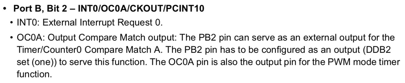
In the description of OC0A pin, it shows “The OC0A pin is also the output pin for the PWM mode timer function”.
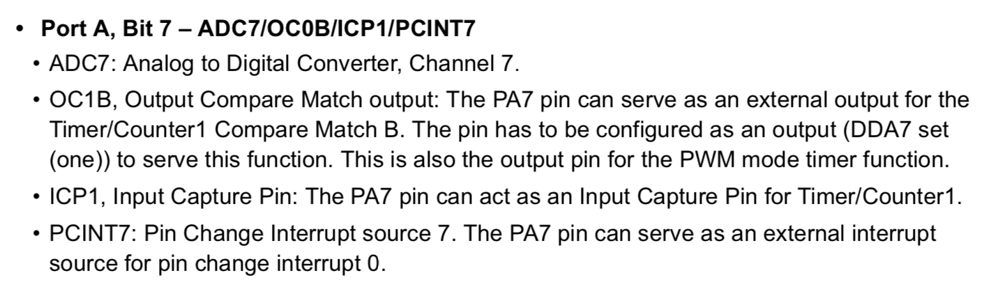
Also, I found those:
(the figure write “OC1B” but I think it would be a misprint of “OC1A”)
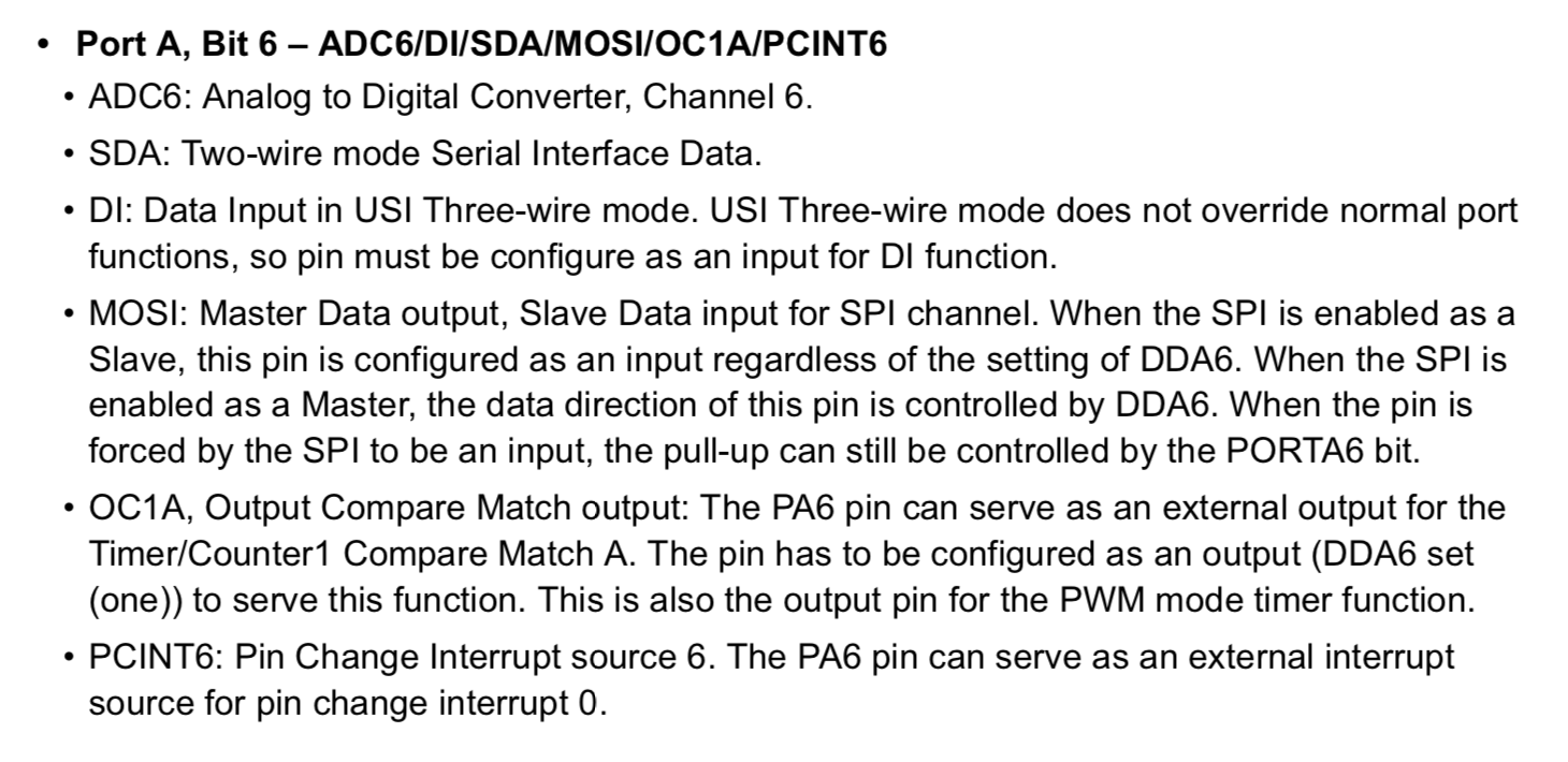
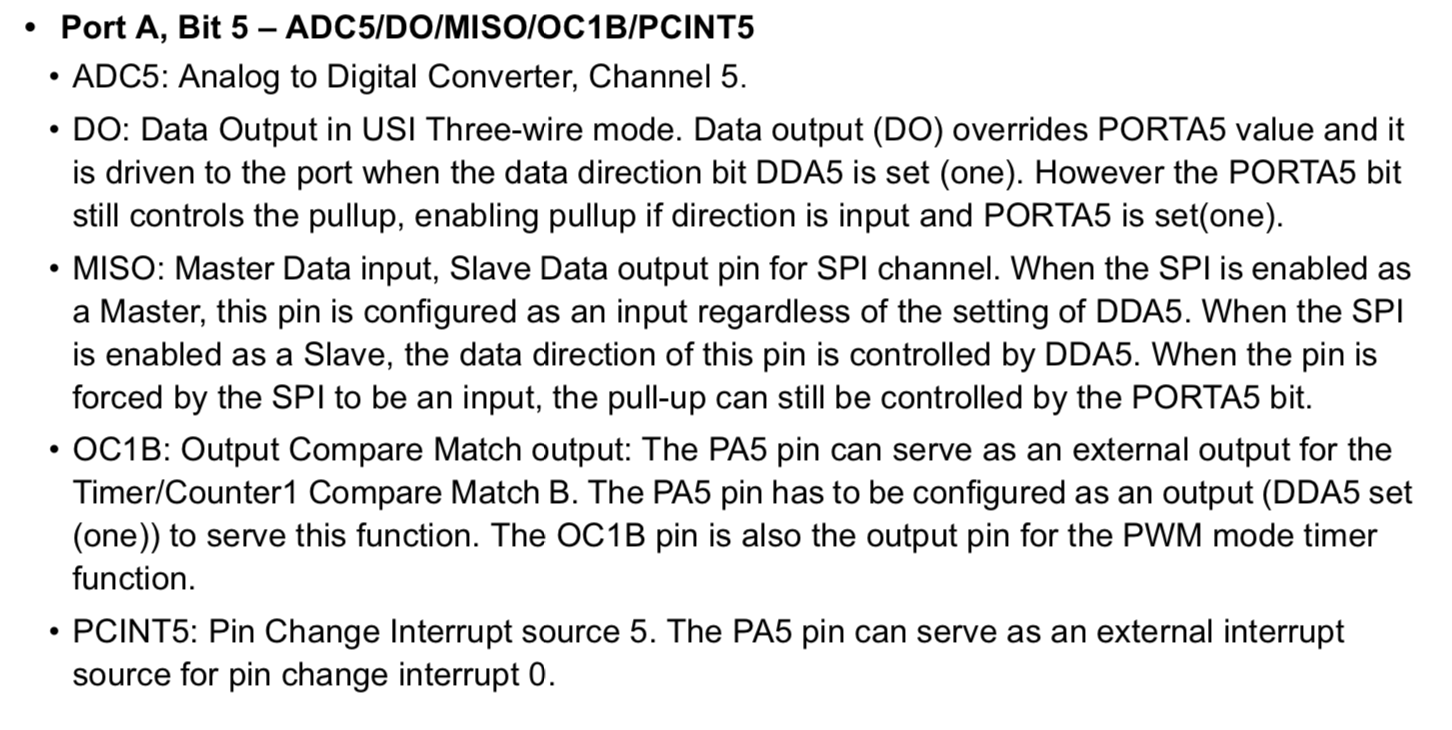
From those descriptions of datasheet, OC0A, OC0B, OC1A and OC1B are assigned as PWM output pins. Therefore, if I want to connect some motors to the microcontrollers, I could connect to PB2(OC0A),PA7(OC0B),PA6(OC1A) and PA5(OC1B).
Testing with breadboard
One of the big mistake in making input devices (last week assignment) is that I begun from designing my original circuit by EAGLE without checking its rightness. It occurs so many errors and I couldn’t fix them before starting review time.
Therefore, Kamakura instructors recommended me to start from designing circuits with breadboard. Breadboard is very useful to check whether the circuits could work or not.
First, I make Neil’s sample board that works two servo motors in software PWM. I used Tower Pro SG-90, that works in 4.8V. And, I also used a benchtop power suppuly.

Then, I uploaded sample C code. And, it could works well.
Then, I try to add one more servo motor. In the sample board, PWM line in each servo motors connect to PA6 and PA7. From the description of the datasheet, there are two more pins for PWM time counter (PA5 and PB3). I connect 3rd servo motor to PB3.

Then, I revise sample code to work servo motor connecting to PB3. First, I added port direction and pins.
#define PWM_portB PORTB
#define PWM_directionB DDRB
#define PWM_pin_2 (1 << PB2)
Then, in the main function, I set PB3 to PWM output.
clear(PWM_portB, PWM_pin_2);
output(PWM_directionB,PWM_pin_2);
Finally, in the main loop, I added the following.
set(PWM_portB,PWM_pin_2);

clear(PWM_portB,PWM_pin_2);
The revised code is here. Then, I uploaded it......
It works well.... !!!
Voltage drop check
I checked the condition of power supply. One servo motor use 4.8 Voltage for rotating. It will occur some voltage drop when using it. The more servo motors I use, the more voltage drop would occur.
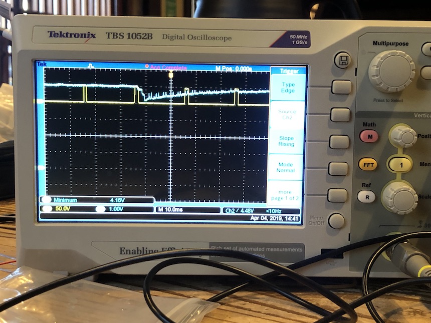
I use Benchtop Power Supply and Oscilloscope in the lab to check the value of voltage drop. First, I set the voltage rate on Benchtop Power Supply to 6.2v, and the voltage in the curcuit is 5.0v.
The following pic shows the graph of oscilloscope that connect three servo motors. It shows that the voltage is 4.16v.
The following pic show the graph of oscilloscope that connect two servo motors. It show that the voltage is 4.48v.
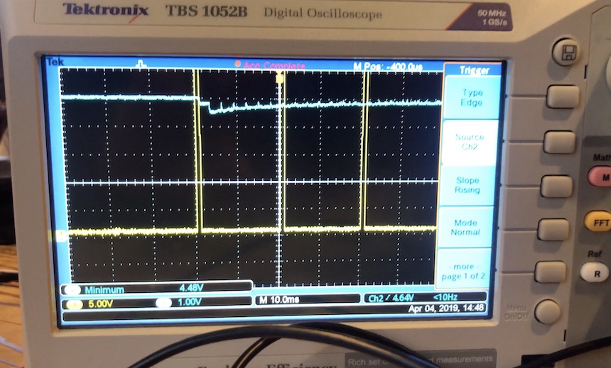
From these results, the value of voltage drop in one servo motor would be about 0.3v. If I add one motor to the microcontroller board, the voltage would be dropped 0.3v.
Designing and Milling
Through examining with breadboard, I confirmed the circuit and the program is correct. So, I start to design the board with Autodesk Eagle. The following parts is required to add to the board.
- ATtiny44 microcontroller x 1
- 5.0v regulator x 1
- 20MHz resonator x 1
- 2x3 Jumper Pins x 3 … two for connecting servo motor, one for connecting to ISP.
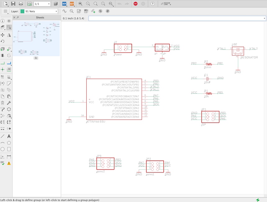
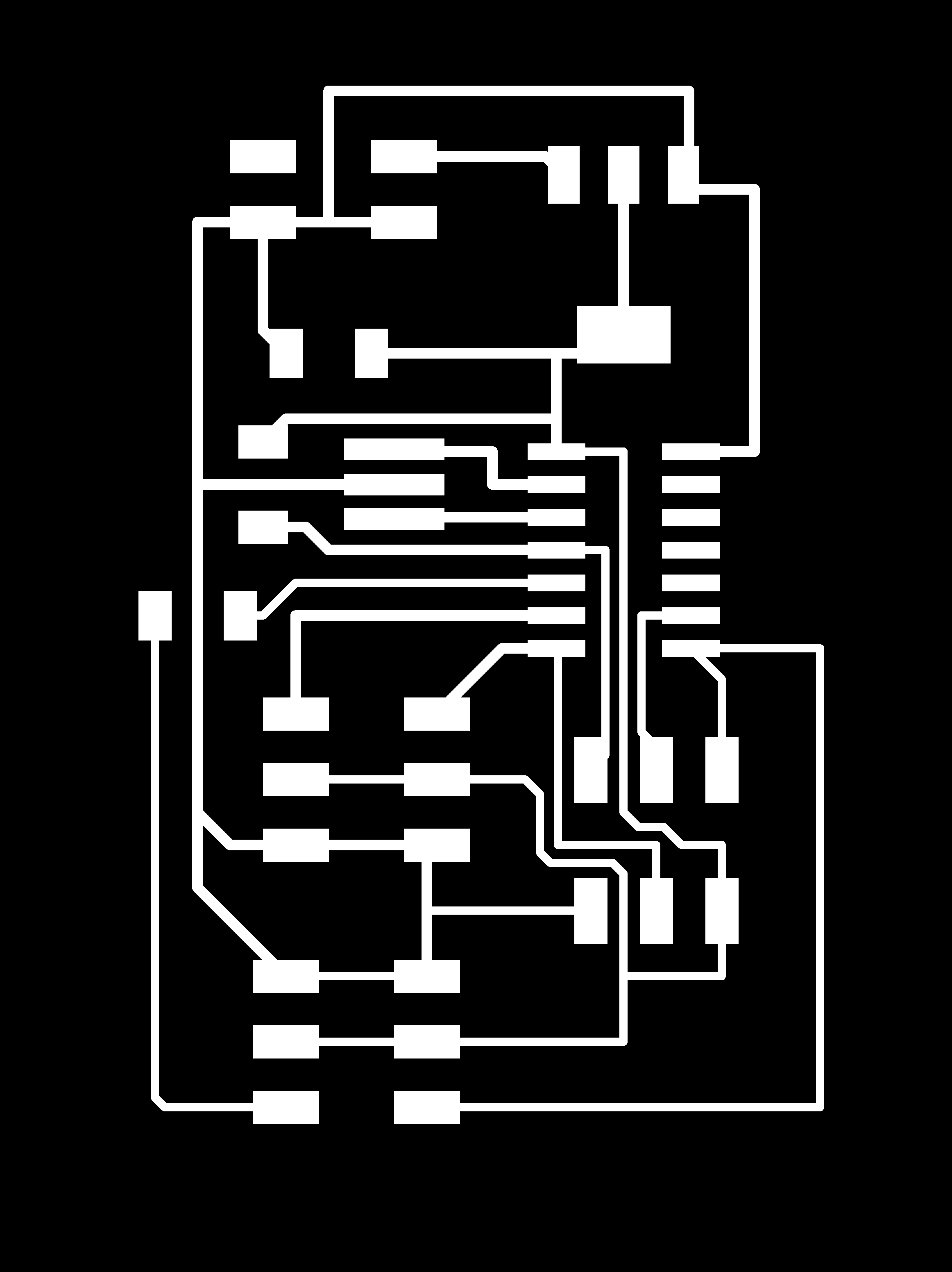
Also, designing the pattern of the board.

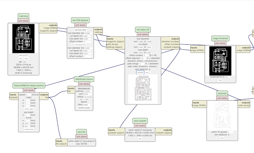
Then, exported in png file and read in mods to make CAM file for Roland SRM-20.
Milling the board....
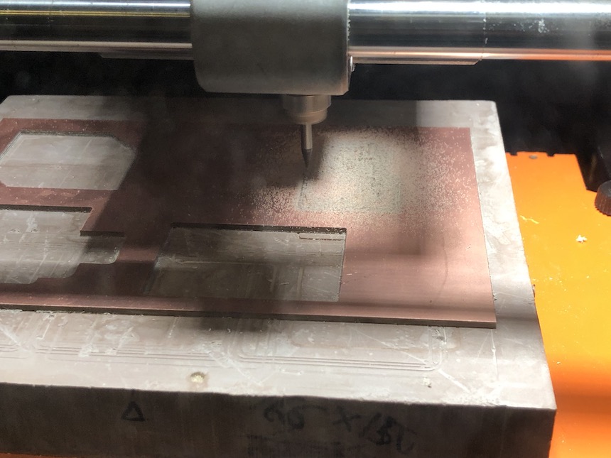
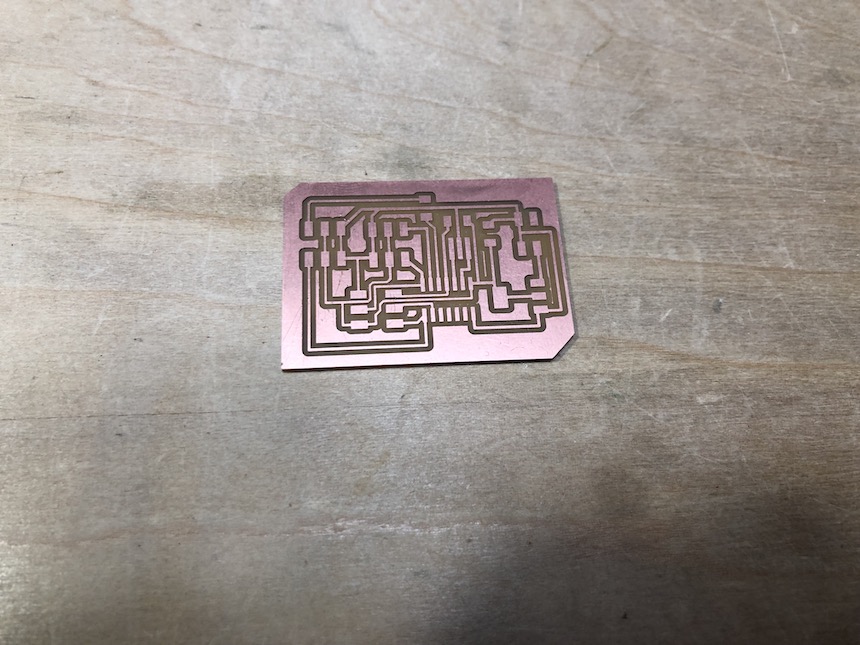
Then soldering the parts.

Writing the program for rotating three servo motors
After finishing soldering, I wrote the same program that I wrote for the breadboard version of microcontroller board.
Then tried to rotate three servo motors…
It works well !!!
Writing the program for rotating four servo motors
Then, I tried to rotate four servo motors in my designed microcontroller board. It would be simple to add some PWM port to rotate it, and the port would be PA5.
Here is the code for 4 servo motors.
#include <avr/io.h>
#include <util/delay.h>

#define output(directions,pin) (directions |= pin) // set port direction for output
#define set(port,pin) (port |= pin) // set port pin
#define clear(port,pin) (port &= (~pin)) // clear port pin
#define pin_test(pins,pin) (pins & pin) // test for port pin
#define bit_test(byte,bit) (byte & (1 << bit)) // test for bit set
#define position_delay() _delay_ms(1000)

#define PWM_port PORTA
#define PWM_direction DDRA
#define PWM_pin_0 (1 << PA6)
#define PWM_pin_1 (1 << PA7)
#define PWM_pin_3 (1 << PA5)

#define PWM_portB PORTB
#define PWM_directionB DDRB
#define PWM_pin_2 (1 << PB2)

#define loop_count 30

int main(void) {
   //
   // main
   //
   uint8_t i;
   //
   // set clock divider to /1
   //
   CLKPR = (1 << CLKPCE);
   CLKPR = (0 << CLKPS3) | (0 << CLKPS2) | (0 << CLKPS1) | (0 << CLKPS0);
   //
   // set PWM pins to output
   //
   clear(PWM_port, PWM_pin_0);
   output(PWM_direction, PWM_pin_0);
   clear(PWM_port, PWM_pin_1);
   output(PWM_direction, PWM_pin_1);
   clear(PWM_portB, PWM_pin_2);
   output(PWM_directionB,PWM_pin_2);
   clear(PWM_port,PWM_pin_3);
   output(PWM_port,PWM_pin_3);

   //
   // main loop
   //
   while (1) {
      //
      // 1 ms on time, both
      //
      for (i = 0; i < loop_count; ++i) {
         set(PWM_port,PWM_pin_0);
         set(PWM_port,PWM_pin_1);
           set(PWM_port,PWM_pin_3);
           set(PWM_portB,PWM_pin_2);
         _delay_us(1000);
         clear(PWM_port,PWM_pin_0);
         clear(PWM_port,PWM_pin_1);
           clear(PWM_portB,PWM_pin_2);
           clear(PWM_port,PWM_pin_3);
         _delay_us(19000);
      }
      //
      // 1.5 ms on time, both
      //
      for (i = 0; i < loop_count; ++i) {
         set(PWM_port,PWM_pin_0);
         set(PWM_port,PWM_pin_1);
           set(PWM_portB,PWM_pin_2);
           set(PWM_port,PWM_pin_3);
         _delay_us(1500);
         clear(PWM_port,PWM_pin_0);
         clear(PWM_port,PWM_pin_1);
           clear(PWM_portB,PWM_pin_2);
           clear(PWM_port,PWM_pin_3);
         _delay_us(18500);
      }
      //
      // 2 ms on time, both
      //
      for (i = 0; i < loop_count; ++i) {
         set(PWM_port,PWM_pin_0);
         set(PWM_port,PWM_pin_1);
           set(PWM_portB,PWM_pin_2);
           set(PWM_port,PWM_pin_3);
         _delay_us(2000);
         clear(PWM_port,PWM_pin_0);
         clear(PWM_port,PWM_pin_1);
           clear(PWM_portB,PWM_pin_2);
           clear(PWM_port,PWM_pin_3);
         _delay_us(18000);
      }
      //
      // 1 ms on time, channel 0
      //
      for (i = 0; i < loop_count; ++i) {
         set(PWM_port,PWM_pin_0);
         _delay_us(1000);
         clear(PWM_port,PWM_pin_0);
         _delay_us(19000);
      }
      //
      // 1 ms on time, channel 1
      //
      for (i = 0; i < loop_count; ++i) {
         set(PWM_port,PWM_pin_1);
         _delay_us(1000);
         clear(PWM_port,PWM_pin_1);
         _delay_us(19000);
      }
      //
      for (i = 0; i < loop_count; ++i){
            set(PWM_portB,PWM_pin_2);
            _delay_us(1000);
            clear(PWM_portB,PWM_pin_2);
            _delay_us(19000);
      }

      //
      for (i = 0; i < loop_count; ++i){
           set(PWM_port,PWM_pin_3);
           _delay_us(1000);
           clear(PWM_port,PWM_pin_3);
           _delay_us(1000);
      }


      // 1.5 ms on time, channel 0
      //
      for (i = 0; i < loop_count; ++i) {
         set(PWM_port,PWM_pin_0);
         _delay_us(1500);
         clear(PWM_port,PWM_pin_0);
         _delay_us(18500);
         }
      //
      // 1.5 ms on time, channel 1
      //
      for (i = 0; i < loop_count; ++i) {
         set(PWM_port,PWM_pin_1);
         _delay_us(1500);
         clear(PWM_port,PWM_pin_1);
         _delay_us(18500);
         }
      //
      for(i = 0; i < loop_count; ++i){
           set(PWM_portB,PWM_pin_2);
           _delay_us(1500);
           clear(PWM_portB,PWM_pin_2);
           _delay_us(18500);
      }

      for(i = 0; i < loop_count; ++i){
           set(PWM_port,PWM_pin_3);
            _delay_us(1500);
          clear(PWM_port,PWM_pin_3);
          _delay_us(18500);

      }


      // 2 ms on time, channel 0
      //
      for (i = 0; i < loop_count; ++i) {
         set(PWM_port,PWM_pin_0);
         _delay_us(2000);
         clear(PWM_port,PWM_pin_0);
         _delay_us(18000);
         }
      //
      // 2 ms on time, channel 1
      //
      for (i = 0; i < loop_count; ++i) {
         set(PWM_port,PWM_pin_1);
         _delay_us(2000);
         clear(PWM_port,PWM_pin_1);
         _delay_us(18000);
      }


      for (i = 0; i < loop_count; ++i){
           set(PWM_portB,PWM_pin_2);
            _delay_us(2000);
            clear(PWM_portB,PWM_pin_2);
             _delay_us(18000);
      }

      for(i = 0; i < loop_count; ++i){
           set(PWM_port,PWM_pin_3);
           _delay_us(2000);
           clear(PWM_port,PWM_pin_3);
           _delay_us(18000);
       }
     }
   }
… It works well!!!!
Week 12 Files
- EAGLE Schema File fabacademy_assignment_week12.sch
- EAGLE Design File fabacademy_assignment_week12.brd
- board trace file week12_trace.png
- board interor file week12_interor.png
- C code for rotating three servo motors hello.servo.44.addthreemotors.c
- C code for rotating four servo motors hello.servo.44.addfourmotors.c