9. Embedded programming
People who are really serious about software should make their own hardware. — Alan Curtis Kay (talk at Creative Think seminar, 20 July 1982)
The topic of this week is Embedded Programming. I learned basic architectures of ATTiny44 micro-controller through reading its datasheet. Then, in order to get used to workflow of programming to the micro-controller, I tried to write programs to a echo-helloworld board, which I made two weeks ago (in the assignment of “Electronics Design.”). Class video is here.

Assignment
- individual assignment:
- read a microcontroller data sheet
- program your board to do something, with as many different programming languages and programming environments as possible
- group assignment:
- compare the performance and development workflows for other architectures
In the group assignment, we tried to program on ARM micro-controller, and I tried to program on Raspberry Pi with different languages (Python and JavaScript).
Our group assignment page is here.
Reading data sheet of ATTiny44
The data sheet of ATTiny44 is here. The data sheet is too long, then I picked up some important part to program on the board.
Feature (p.1)
I picked the following information from this first brief page.
High Endurance, Non-volatile Memory Segments:
- 2K/4K/8K Bytes of In-System, Self-programmable Flash Program Memory
- 128/256/512K Bytes of In-System Programmable EEPROM (Electrically Erasable Programmable Read-Only Memory).
- 128/256/512K Bytes of Internal SRAM
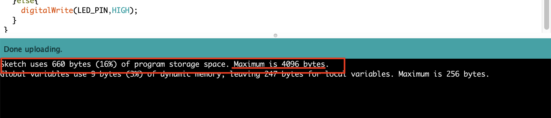
Those information give me how much the maximum size of compiled program should be. From this information, ATTiny44 have 4K Bytes Maximum Flash Memory for programming. And, I confirmed it when I write the program on the Arduino.
Speed Grade:
- 0-4 MHz @ 1.8-5.5V
- 0-10 MHz @ 2.7-5.5V
- 0-20 MHz @ 4.5-5.5V
From this information, the speed of micro-controllers depend on the voltage.
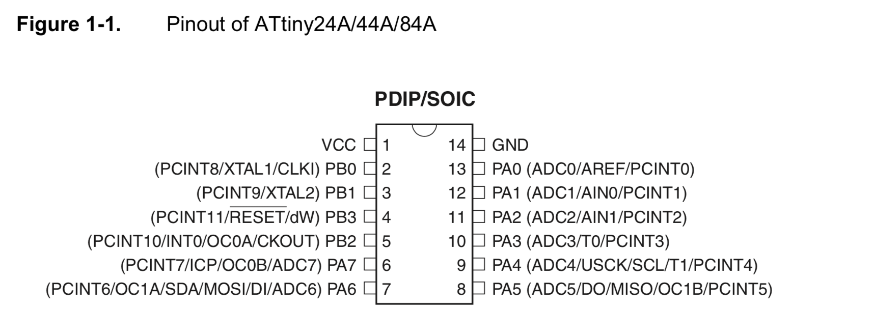
Pin Configurations and Descriptions (p.2)
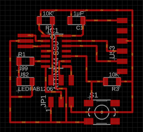
This is one of the important part because I could find out which pin connect to what parts on the board. In my echo-hello world board, Switch is connected to PA3 and LED is connected to PA7.
Schema of my echo-hello world board
Here are pin descriptions that wrote in p.3.
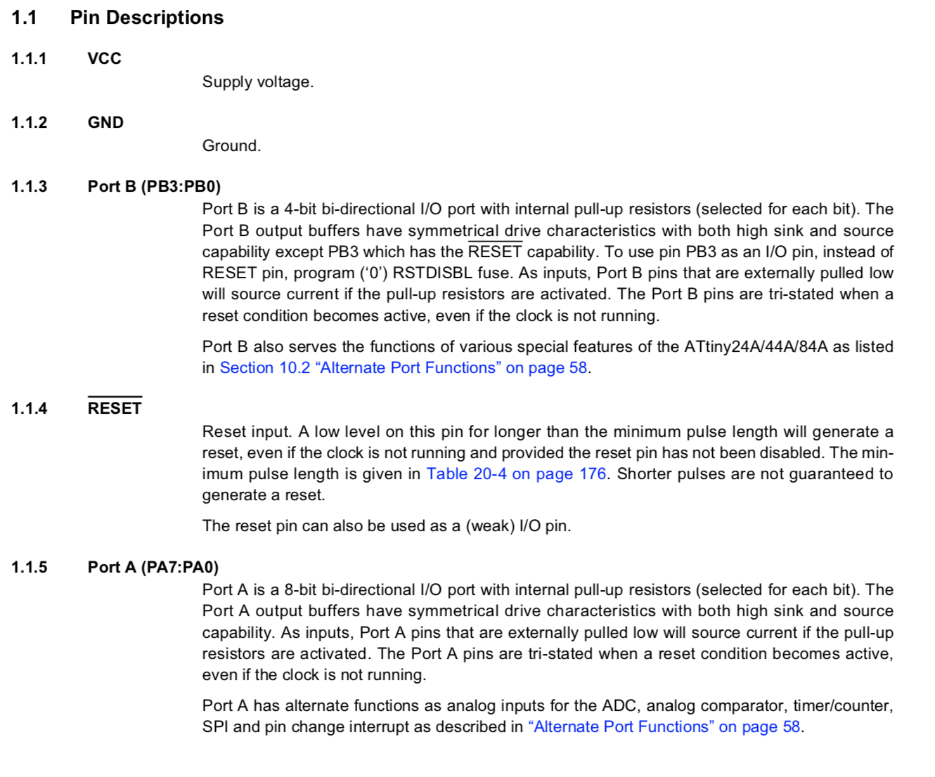
From these information, I could find
- PortB (PB3:PB0) is a 4-bit bi-diractional I/0 port with internal pull-up resisters.
- PortA is an 8-bit bi-directional I/O port with internal pull-up registers.
- “Bi-diractional I/0 port” means I can use those ports both Input and Output.
- Only Port A has alternate functions as analog inputs for ADC, analog comparator, timer/counter, SPI and pin change interrupt. If I want to use Analog Input/Output, I have to choose Port A.
I/O Port (p.53 ~)
As checked above, the ports are bi-directional I/O ports with optional internal pull-ups. Each ports have registers to pull-up/down and it is important to know that to control directions, on/off of input/output.
Configuring the pin
In p.54, configuration of the pins are explained:
Each port pin consists of three register bits: DDxn, PORTxn, and PINxn. As shown in “Register Description” on page 66, the DDxn bits are accessed at the DDRx I/O address, the PORTxn bits at the PORTx I/O address, and the PINxn bits at the PINx I/O address.

The DDxn bit in the DDRx Register selects the direction of this pin. If DDxn is written logic one, Pxn is configured as an output pin. If DDxn is written logic zero, Pxn is configured as an input pin.

If PORTxn is written logic one when the pin is configured as an input pin, the pull-up resistor is activated. To switch the pull-up resistor off, PORTxn has to be written logic zero or the pin has to be configured as an output pin. The port pins are tri-stated when reset condition becomes active, even if no clocks are running.

If PORTxn is written logic one when the pin is configured as an output pin, the port pin is driven high (one). If PORTxn is written logic zero when the pin is configured as an output pin, the port pin is driven low (zero).
From this explanation…
If I set the direction of the pin (input/output), I should configure DDRX (DDRA,DDRB) bit. For example, if I want to set output of PA7 pin that is connected to LED, in C-language, should write:
DDRA |= (1<<PA7)
If I set default pull-up/down of the pin (HIGH or LOW), I should configure PORTx bit. If the pin is configured as an input pin, the pull-up register is (automatically) activated. If I want to switch pull-up register off, I should configure to write logic zero in PORTx bit. For example, if I want to set PA7 pin (connected to the LED) to HIGH, I should write in C-language:
PORTA |= (1<<PA7)
Other register information are in p.66

Analog/Digital Converter
Analog/Digital Converters are important for reading values from sensors. Datasheet is helpful to find out which pins are configured as A/D converters.
According to the figure of pinout, the following pins are assigned as ADC.
- PA1
- PA2
- PA3
- PA4
- PA5
- PA6
- PA7
Those info works when I make an original PCB board included some input devices. Please also see week 11: assignment of Input Devices.
PWM: Palse Width Modulation Control
PWM (Palse Width Modulation) are also important for controling some motors (DC motors, servo, Stepper motors) from the microcontrollers.
To find out which pins are assigned as PWM output, I read details of each pin configurations and I could find the following descriptions:
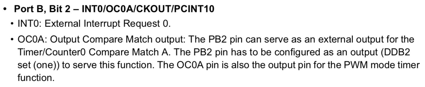
In the description of OC0A pin, it shows “The OC0A pin is also the output pin for the PWM mode timer function”.
Also, I found those:
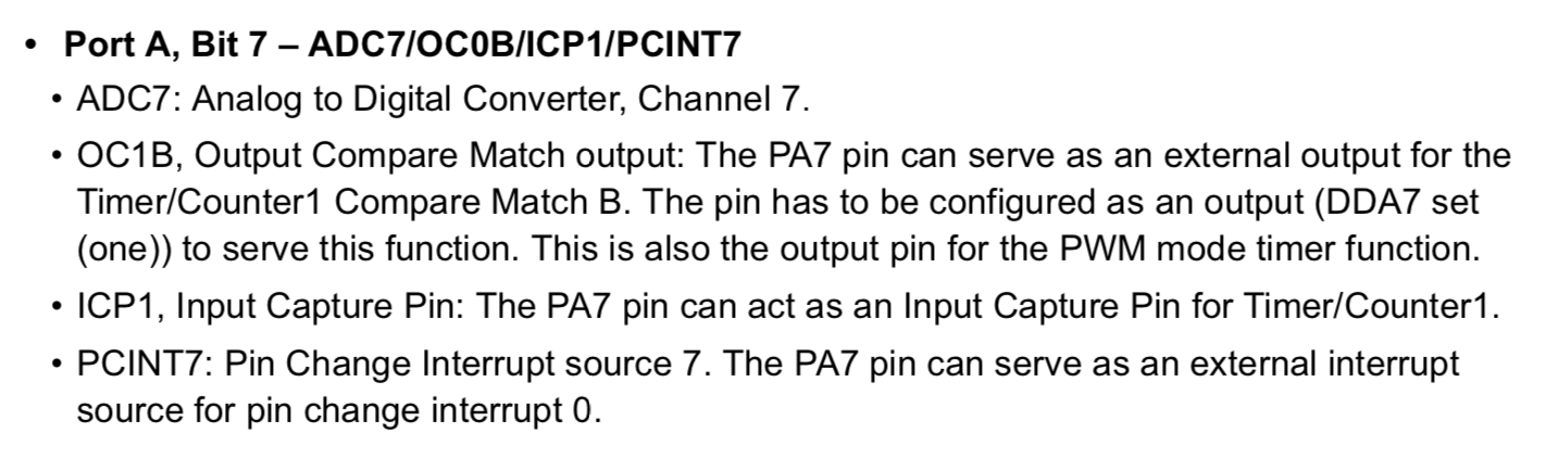
(the figure write “OC1B” but I think it would be a misprint of “OC1A”)
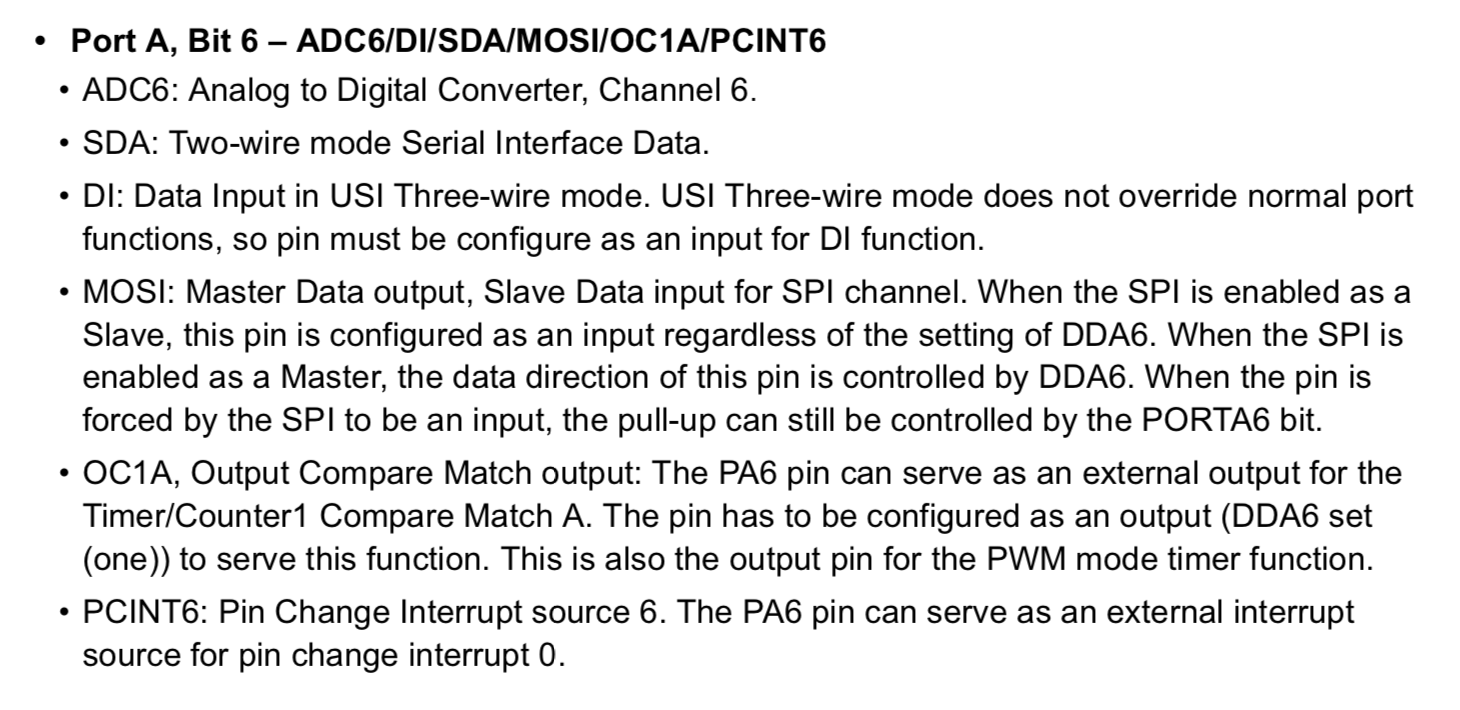
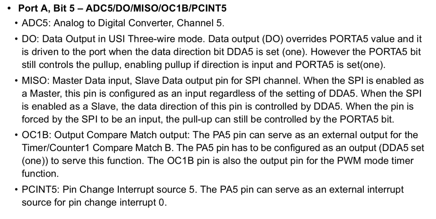
From those descriptions of datasheet, OC0A, OC0B, OC1A and OC1B are assigned as PWM output pins. Therefore, if I want to connect some motors to the microcontrollers, I could connect to PB2(OC0A),PA7(OC0B),PA6(OC1A) and PA5(OC1B).
Those info works when I make an original PCB board controlling three servo motors. Please also see week 12: assignment of Output Devices.
Programming on the board
Based on my finding from the data sheet, I tried to write programs in Arduino and C-language to
- Blink LED in one second intervals
- Bling LED when switch is pushed
Arduino
It is easy to write program for AVR micro-controller by Arduino because I just setup some libraries to install. With following the tutorial page, I setup the Arduino ATTiny support.
When programming on Arduino board, we should take care that the pinouts on the micro controller are not the same numbers in the Arduino code. According to the tutorial page, the correspondence of pin-out numbering between ATTiny micro controller and Arduino are :
| ATTiny44 Pin Number | Arduino Pin Number | Details |
|---|---|---|
| 1 | VCC (+) | |
| 2 | Pin 10 | |
| 3 | Pin 09 | |
| 4 | RESET | |
| 5 | Pin 08 | PWM |
| 6 | Pin 07 | PWM, Analog Input 7 |
| 7 | Pin 06 | MOSI, PWM, Analog Input 6 |
| 8 | Pin 05 | Analog Input 5, PWM, MISO |
| 9 | Pin 04 | Analog Input 4, SCK |
| 10 | Pin 03 | Analog Input 3 |
| 11 | Pin 02 | Analog Input 2 |
| 12 | Pin 01 | Analog Input 1 |
| 13 | Pin 00 | Analog Input 0, AREF |
| 14 | GND (-) |
LED Blink
Here is the code that just blinking LED.
fabacademy_assignment09_LEDBlink.ino
int LED_PIN = 7;

void setup() {
  // put your setup code here, to run once:
  pinMode(LED_PIN,OUTPUT);

}

void loop() {
  // put your main code here, to run repeatedly:
  digitalWrite(LED_PIN, HIGH);
  delay(125);
  digitalWrite(LED_PIN, LOW);
  delay(125);

}
The following movie shows the program works correctly.
LED Blink with Button
Here is the code that blink LED when switch is pushed.
const int LED_PIN = 7;
const int BUTTON_PIN = 3;

int buttonState = 0;

void setup() {
  // put your setup code here, to run once:

  // initialized the LED pin as output
  pinMode(LED_PIN,OUTPUT);
  // initialized the pushbutton pin as an input
  pinMode(BUTTON_PIN,INPUT);


}

void loop() {
  // put your main code here, to run repeatedly:

  buttonState = digitalRead(BUTTON_PIN);

  if(buttonState == HIGH){
    digitalWrite(LED_PIN,LOW);
  }else{
    digitalWrite(LED_PIN,HIGH);
  }
}
And, the following movie shows the program works correctly.
C
(I used my Ubuntu OS PC for writing and uploading C language program on the board.)
I also wrote C language program that has same functions with Arudino. First, I modified sample 5th line of Makefile as follow.
PROJECT=LEDBlink
SOURCES=$(PROJECT).c
MMCU=attiny44
#F_CPU = 20000000
F_CPU = 2500000

...
I changed F_CPU value from 20000000 to 2500000. In the default setting, the time interval of blink was 8 times longer than the period it should be. Typical solution of this problem is to use Atmel Studio 7 which is only available for Windows PC. I have to look for another way to avoid it. According to the document by Mr.Jun Kawahara (Kamakura 2018 Fab Academy student and our instructor in 2019), the solution would be divide the F_CPU value by 8, 20000000 to 2500000 as CKDIV8 remained programmed.
LED Blink
Here is the code to blink LED:
#include <avr/io.h>
#include <util/delay.h>
#include <avr/io.h>

int main(void){

  DDRA = 0b10000000;

  while(1){

    PORTA = 0b10000000;
    _delay_ms(1000);
    PORTA = 0b00000000;
    _delay_ms(1000);

  }
}
To upload this program on the board, I used FabISP as In system programmer, then did the following command.
make -f LEDBlink.c.make
sudo make -f LEDBlink.c.make program-usbtiny-fuses
sudo make -f LEDBlink.c.make program-usbtiny
And, the following movie shows the program is compiled and fused on the board, and finally LED blinked.
LED Blink with Button
Here is the code to blink LED when switch is pushed.
#include <avr/io.h>
#include <util/delay.h>
#define F_CPU 2500000

// LED_PIN: PA7
// BUTTON_PIN: PA3

int main(void){

  //DDRA = (1<<PA7); //PA7 output
  DDRA |= (1<<PA7);
  PINA |= ~(1<<PA3);

  while(1){
    if(!(PINA & (1<<PA3))){
      PORTA |= (1<<PA7);
    }else{
      PORTA &= ~(1<<PA7);
    }
  }
  return 0;

}
The following movie shows the program is compiled and switch start to work for LED blink/unblink.