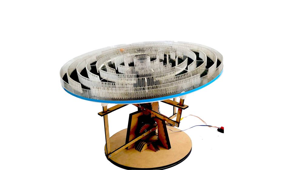
Mechanical Design
Marble Maze

Marble Maze: Video
Mechanism

- 2 axis mechanism
- includes Ball socket joints
- 20:10 Gears, Module: 2, Pressure Angle: 25
- weight carrying capacity : Around 4 kilos
- fastners : self locking mechanism and bolt
Machine Assembly
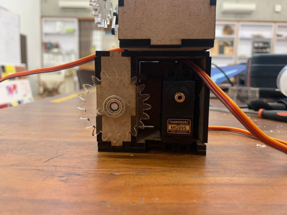
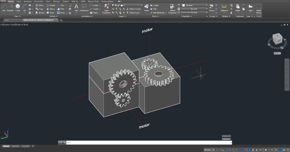
Gear Assembly
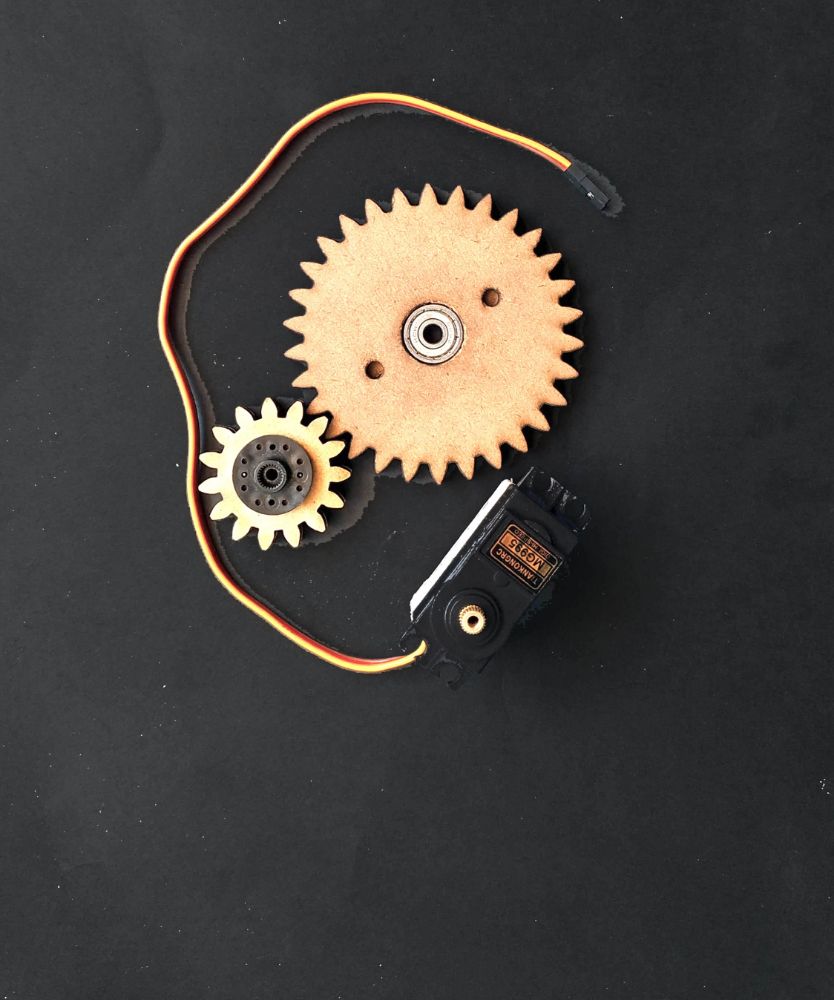
2:1 Servo Drive System
- MG995 Servo
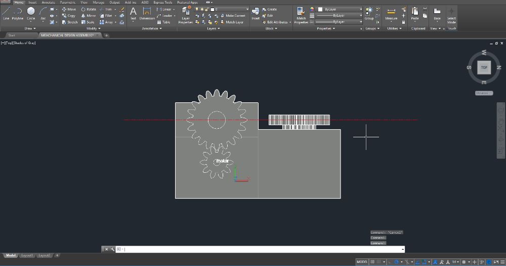
- Laser Cut Involute Gears
- 20:10 Gears, Module: 2, Pressure Angle: 25
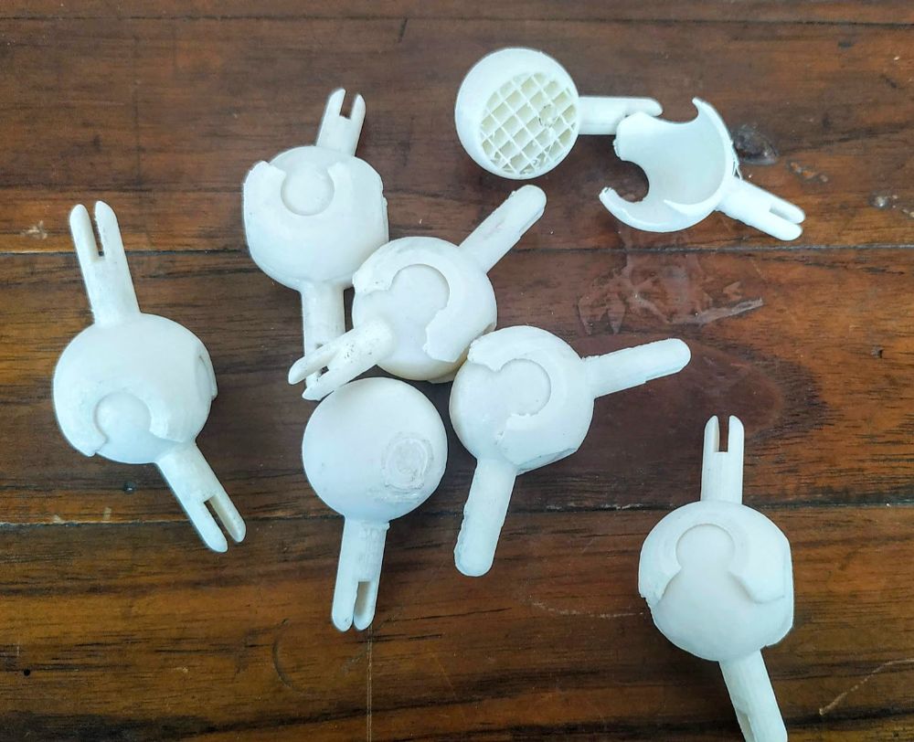
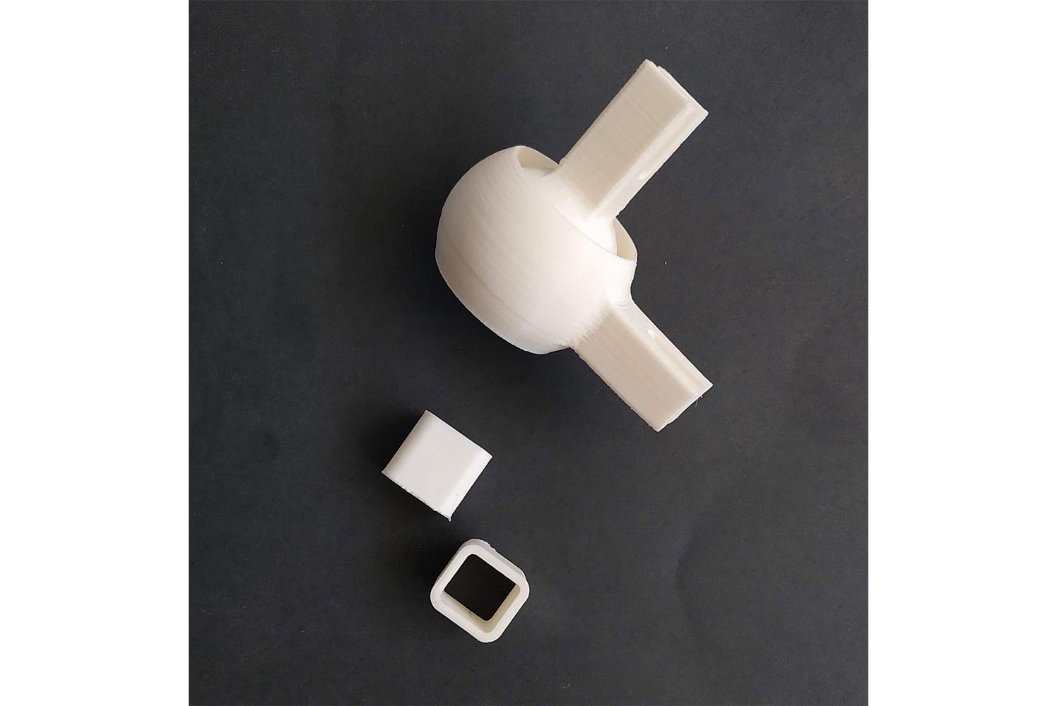
Ball Joints
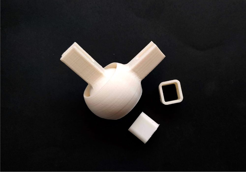
Ball Socket Joints
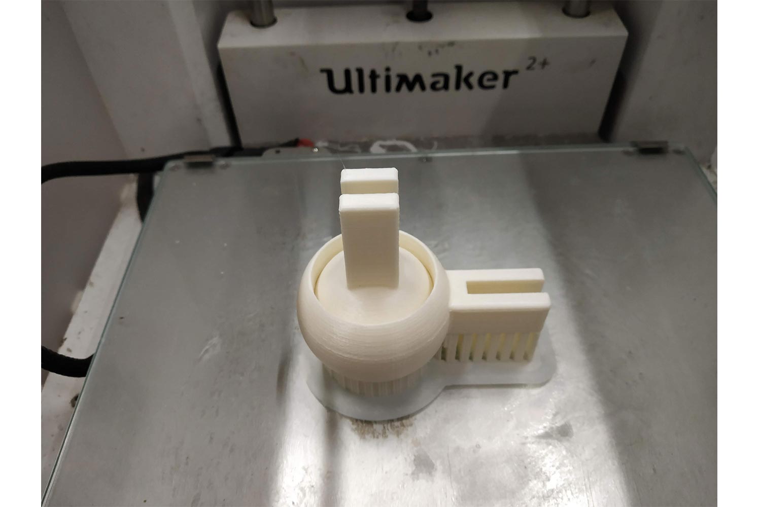
- 3D printed with ABS
- Interlocking Mechanism
- 40 degree freedom of movement
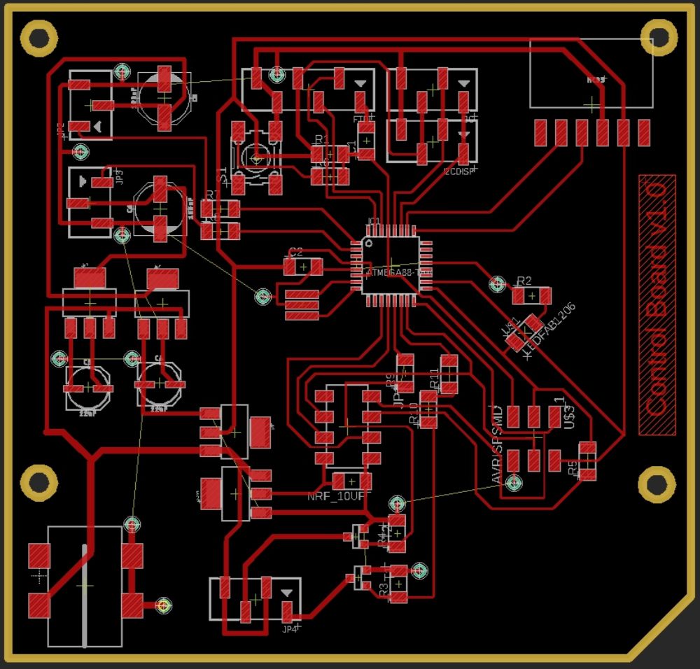
Mainboard
Control Board:
- Atmega328p running at 20MHz 5v
- Seperate power channelf or each MG995 Servo using lm2940
- nrf24l01 for communication
- Dual channel LED strip control using ADS355AN mosfets
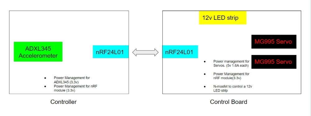
Controller 1: Accelerometer Control

Controller Board using Accelerometer
- ADXL345 accelerometer in i2c
- Atmega328p running at 8MHz, 3.3v in low power mode
- nRF240l01 for communication
- For electronics part visit Samuils website
Controller 2: Joystick Control
Controller Board using joystick
- Joystick Module
- Atmega328p running at 8MHz, 3.3v in low power mode
- nRF240l01 for communication
Acryllic Bending using Laser Kerfs

Acryllic bent using Laser Kerf
- 5mm thickness
- Parametrically generated living hinges
- Edge lighting used to illuminate the entire structure.
- For the Marble maze visit karan's webise.
Group Project Idea:
After spending weeks on deciding what to make ranging from an automated flamethrower to a vending machine, we finally decided on making a marble maze. Our inspiration for the project was the The [amazing] Maze made by Katie Levine and our regional instructor Ohad Meyuhas.

Katie Levine and Or Shoval's The Amazing Maze #FabAcademy @FabLabHub @FabFndn http://t.co/Hjy693p77B pic.twitter.com/jhczbnGDnY
— Fab Academy (@fabacademany) June 10, 2015
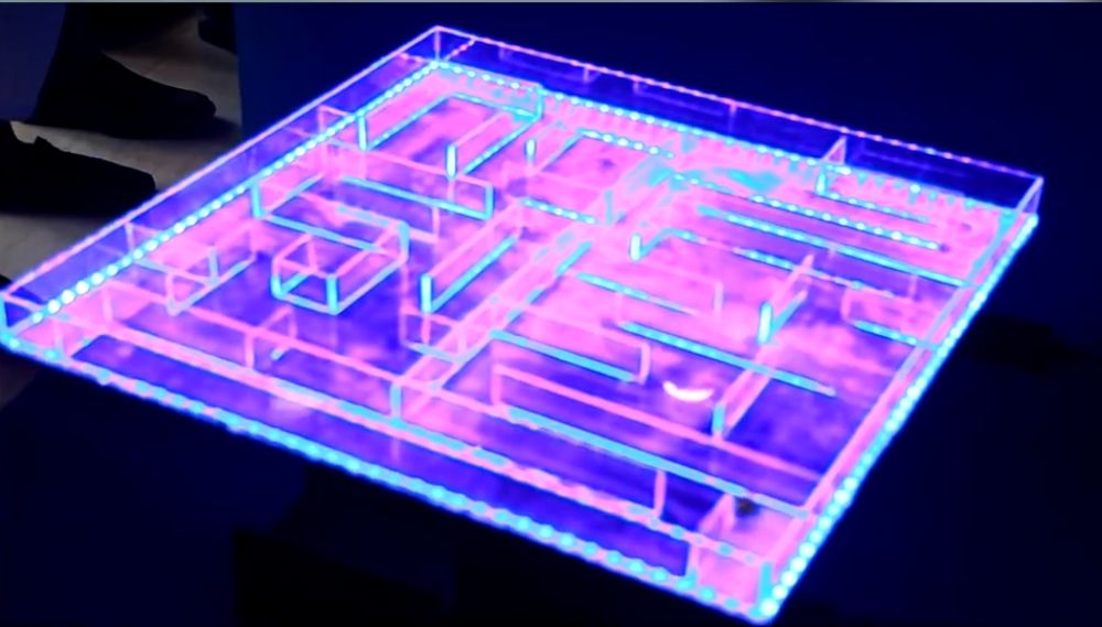
But! for our design of the maze, we wanted it to look 'Out of this world'. Our inspiration for the aesthetics of the project came from on of our members who previously made a similar maze. The Maze construction would be made out of acryllic and we would use LED strips and using Edge lighting, we would make something like this;

Having this goal for aesthetics, increased our mechanical complexity a bit, since we wont be able to keep the motor and the bearings along the sides of the maze, but place it below.
The Plan!
Since we were a group of five people here at CEPT, we decided to make two marble mazes, each uniquely solving the mechanism problem. One with a surefire simple solution we all knew would work, and the second was using a bit more complicated solution, that 'might work'.
The Simple Solution:
The First solution was to use 'one' simple ball socket joint and use two servos to control the tilt table on top of the ball socket.
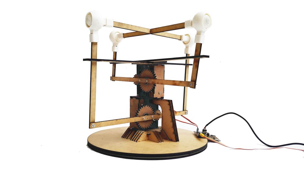
The Not so Simple Solution:
The Not so simple solution was to use four ball socket joints and a servo drive mechanism with a ratio of 2:1 in the bottom.
Work done this Week:
This week, we explored the 'not so simple' solution for our mechanism and made the electronics platform for the entire project. The work progress for this week was;
- Started making of the Marble maze
- Proof of concept prototype model of our 4 Ball Socket Mechanism using
- Servo Drive Mechanism for the mechanism with a 2:1 gear ratio.
- Electronics platform development for the Control board and the controller.
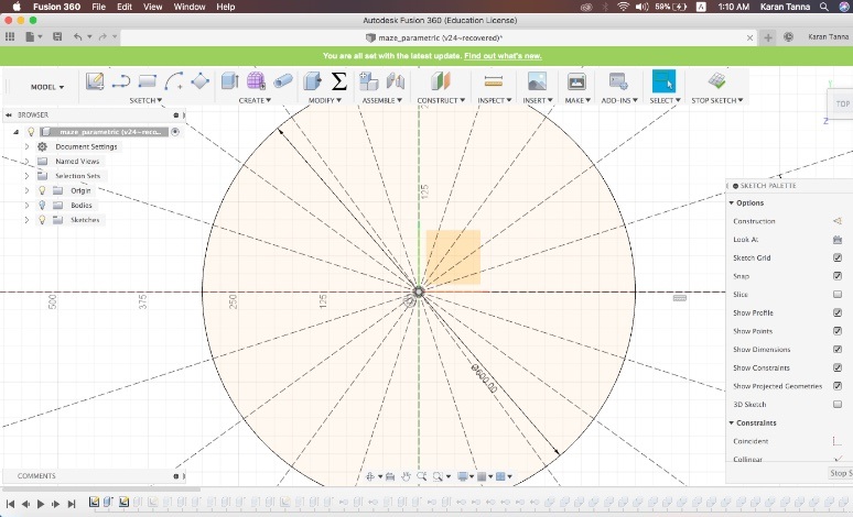
Making of Maze
1. First of all I defined Outer Diameter of maze. (i.e. 60 cm) The I defined geometry of it. Using construction lines with following parameters.
2.First I exruded all radial walls. Then In sketch layer I marked whatever I wanted to cut.
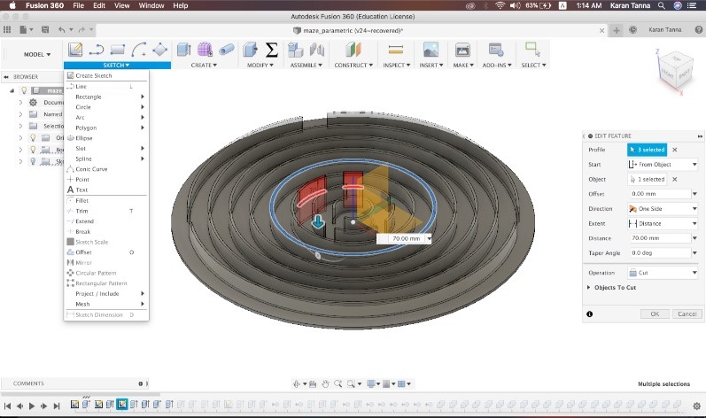
3. kept on going layer by layer from center to outwards. And then I extruded straight sections.

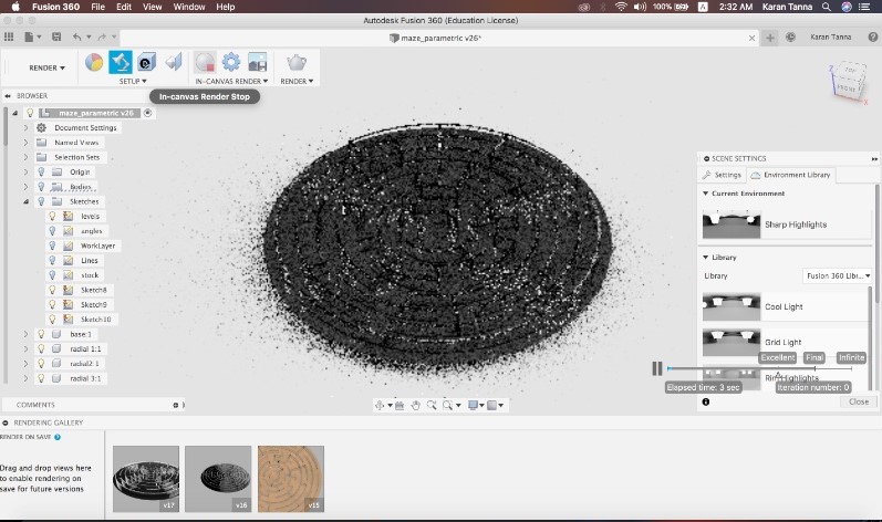
4. Then Once model is done we rendered it using Render mode i Fusion
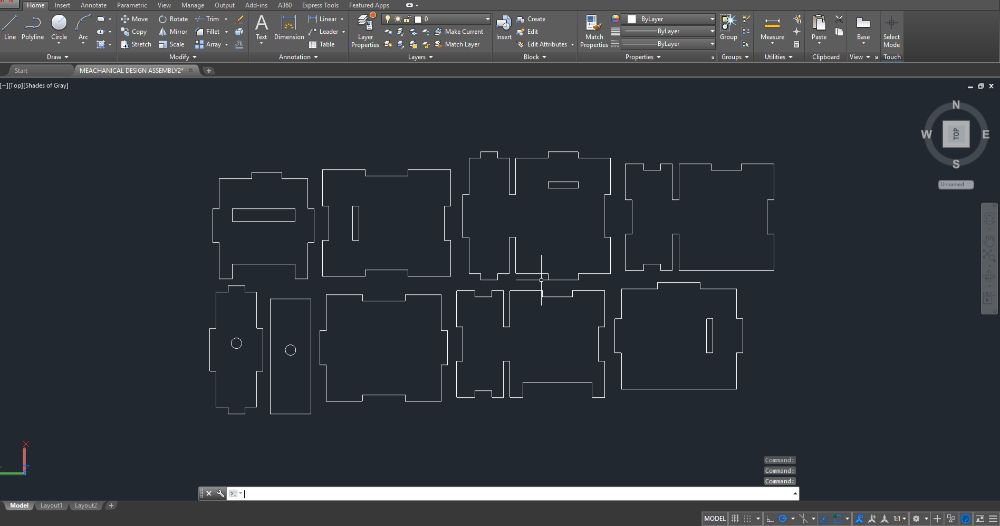
5. After exporting dxf I made some manual changes in Auto-cad where needed.

6. Then We fabricated it with laser.
Design of Mechanism


After Multiple iterations in 3D printing them, we found the right tolerance and settings. and came up with the following mechanism.
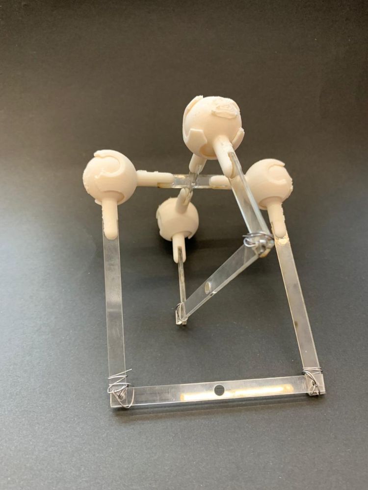
Demostration of 2-axis Movement using 4 Ball sockets:
And here is the code running on the example:
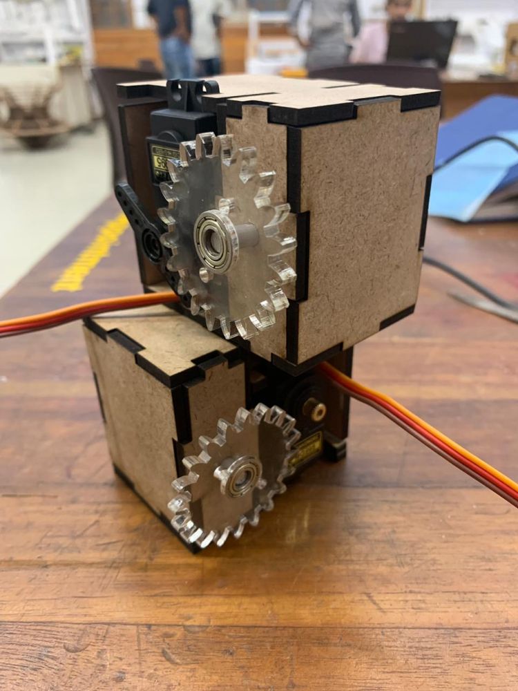
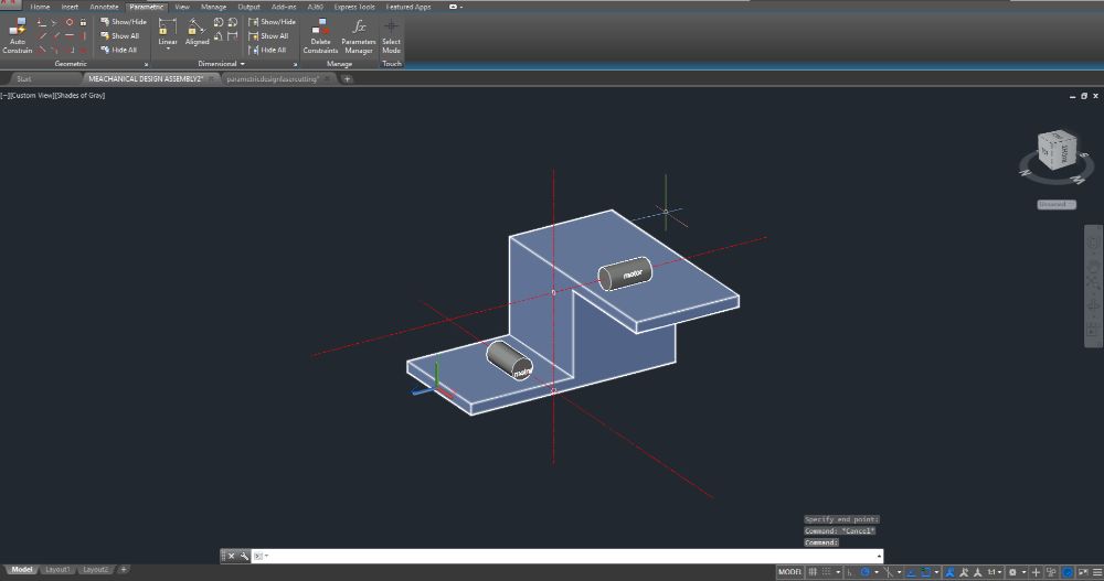
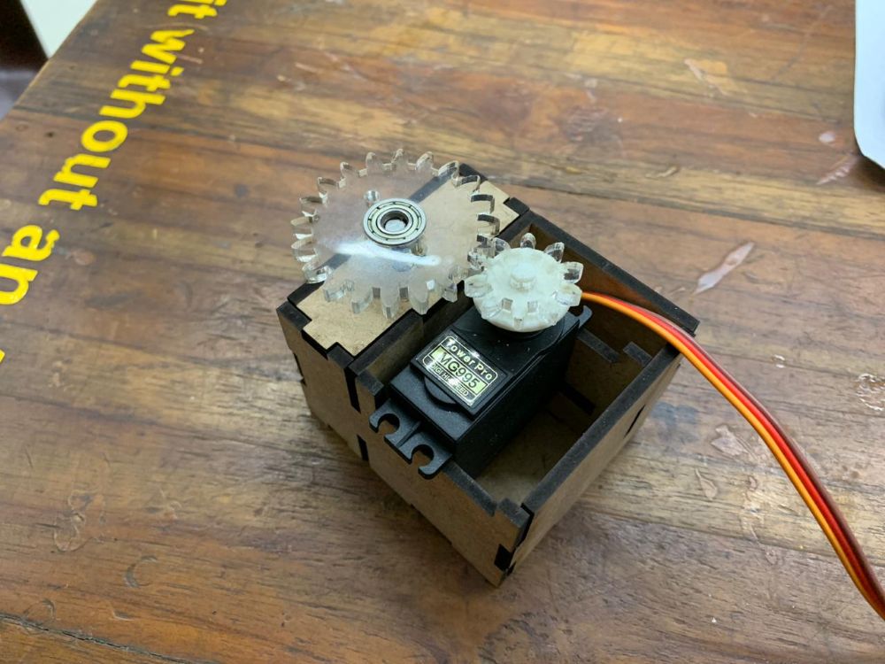
2. 2:1 Gear Drive for MG995 Servos:
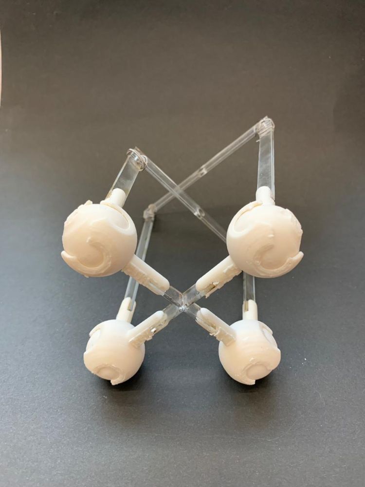
For 2-Axis movement, we needed the gears driving the board in the same vertical axis. The below image was our first sketch in making that.

But since the individual axis were open, the system was not stable. So for the second attempt, we connected the system at top so both would give stability to the other. Also, for the twisting, we added ball socket joints at the upper nodes.
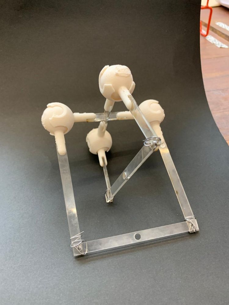
We also changed the design of the base to make it more stable. This was the new design
These are the laser cut parts for this updated base.
This is how it turned out to be.

Upper members of the Mechanism

1. Prototype Model for our 4 Ball Socket Mechanism:
We designed these ball sockets in Fusion 360.
Final Assembly of prototype

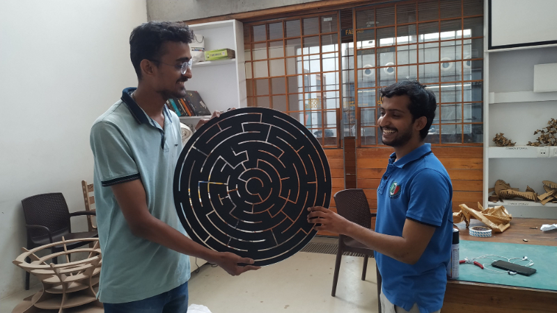
After comfirming thisn mechanism is good enough to work in final machine we started making our original marble maze .
Final model
laser cut parts

3d print parts
Mechanical parts assembly
Testing
Electronics Block Diagram:
After several hours of discussion, we figured the basic electronics block diagram for our circuitry.
Group 1:
Group 2:
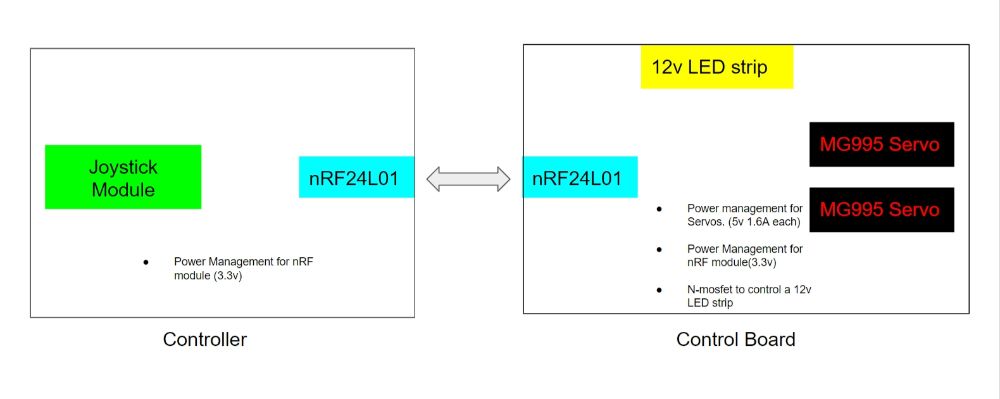
- Both Group Had different Mechanisms to move the Maze, but they both will be using the same two servos.
- Group 1 will be using an Accelerometer in a glove to control the maze while Group 2 will use a joystick module to control it.
- For aesthetics, we will be using 12v LED strips.
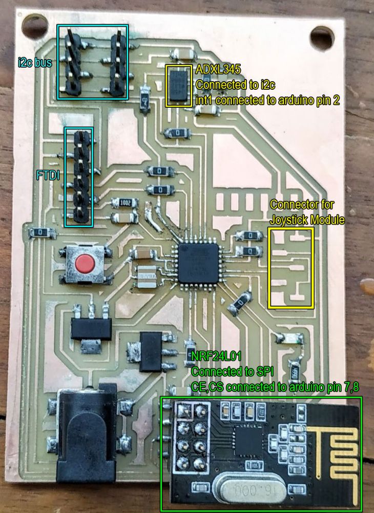
Electronics
Since I am a lazy person, I decided to make a single pair of boards which would work for both the groups. I made the schematics for the controller and the control board while considering that the control board will be the same for both the groups while the controller would have pinouts for both tht accelerometer and the joystick module and these are what I came up with.
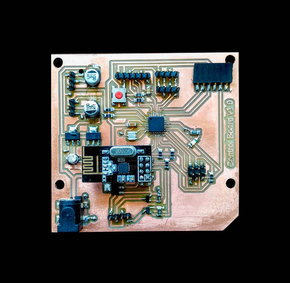
Control Board:

Features:
- Atmega328p 20MHz running on 5v
- Seperate 3.3v power for nrF24L01
- Seperate power management for MG995 Servos using LM2940
- Control Circuit for 12v LED strips using N-Mosfets
- Onboard Devices: nrF24L01, connecting port for HC-05
- Hardware i2c and Serial pinouts

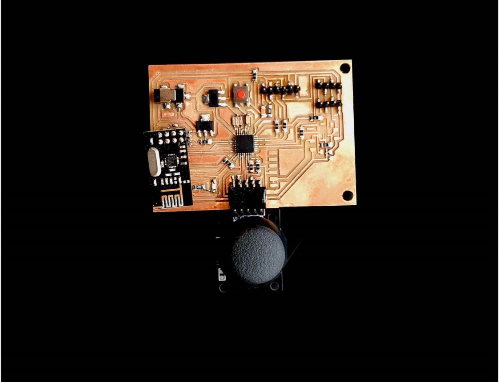
Controller Board:

Features:
- Atmega328p 8MHz running on 3.3v
- Onboard Devices: nrF24L01, ADXL345
- Hardware i2c and Serial pinouts
- Pinout to Connect Joystick Module