Electonics Design
Assignment
Test Equipment Available at the Lab:
The Electronics Test Equipment Available at the lab were;
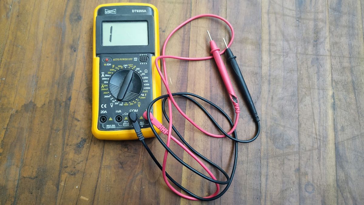
Luckily one of our group members had a better Multimeter and we decided to work with that,
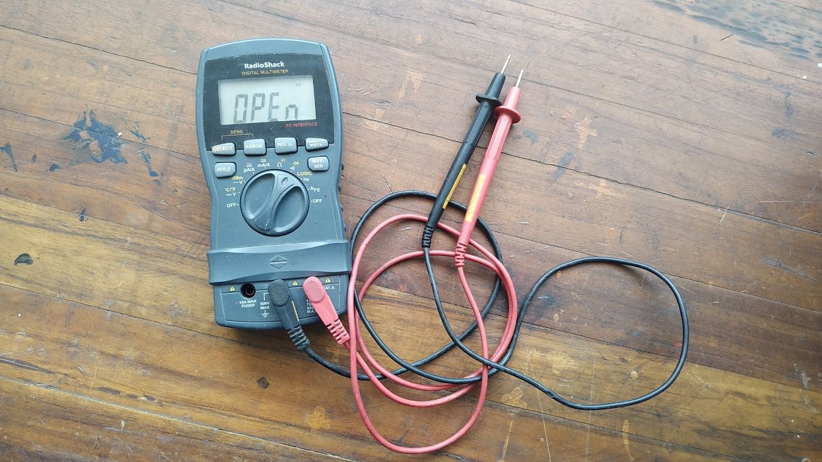
Using a Multimeter:
The most useful tool in our arsenal while working on electronics is the multimeter. It is the most basic means of knowing what's going on in a circuit. This specific multimter, the Radio Shack True-RMS 46-Range Digital Multimeter, has some history to it as well. It was bought by me back in 2015 when Radioshack was going bankrupt as a memnto of it's great service to the electronics community. It is an autoranging multimeter which means, there's minimal knob turning when working with it. There's a myriad of things we can do with it, but here I will cover the most basic and important ones.
For more on multimeters and how to use them, check out SparkFun's amazing tutorial on Multimeters.
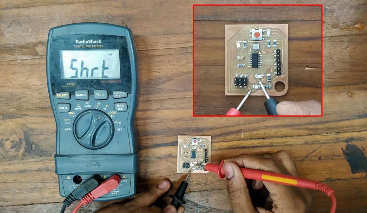
Checking Continuity:
Continuity check between two points can be used to detect shorts in a circuit. If there's a continuity between the two probes,
the multimeter will detect a short and beep. This is probably the most used function in a multimter. It is a very basic test that can
save you from frying your circuits.
To use it, turn the dial to the 'buzzer icon' and touch the probes where you want to check continuity.
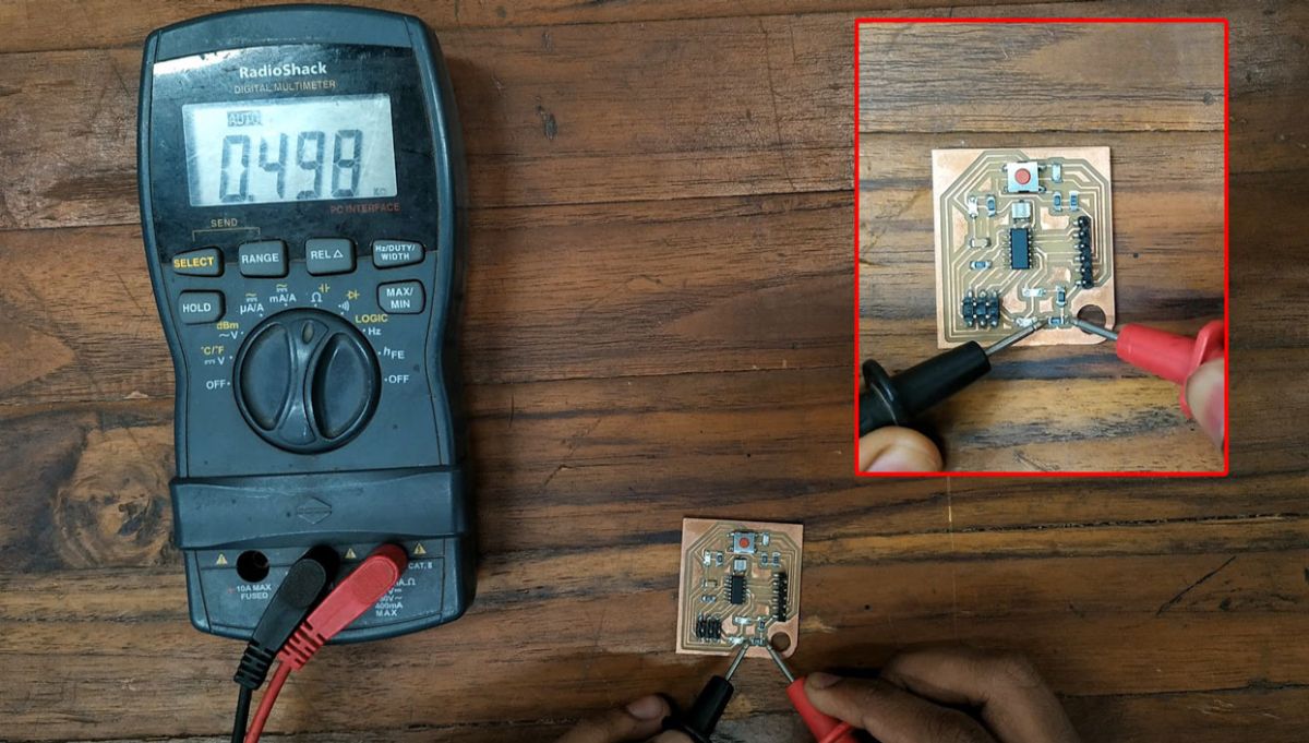
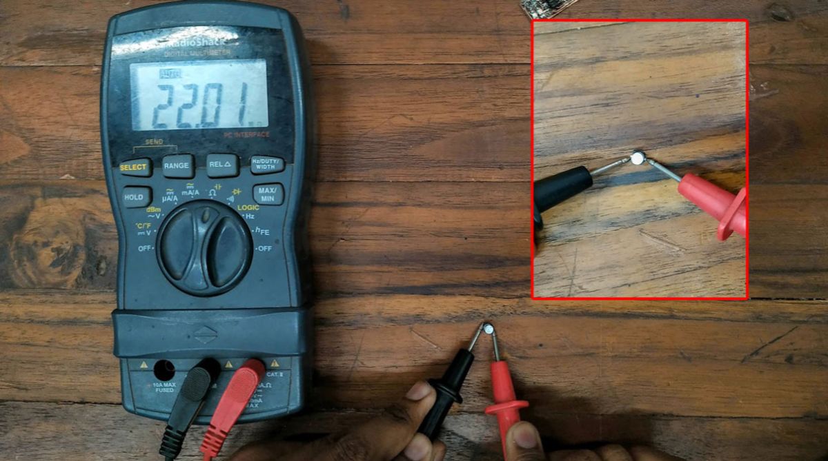
Measuring Resistance:
To measure resistance, move the dial to the 'Ω' icon. Touch the probes to both ends of the resitor you want to check the value of, and the resistor value will show up on the display. Since it is an autoranging multimeter, that's basically all you have to do to measure resistance.
Measuring Capacitance:
To Measure Capacitance, move the dial to the 'Capacitance icon' which is apparently in yellow color and co-incides with the
'Ohm icon'. To select the alternate, capacitance mode, you need to press the 'select' button. The unit should change from ohms to Farads, you're set to measure
capacitance.
Touch the probes to the two ends of the capcitor and the capacitance value should show up on the display.
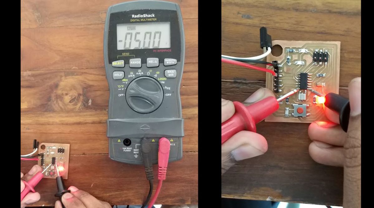
Measuring Voltage:
Voltage difference between two points can be measured by moving the dial to the 'DC voltage' icon and touching the probes on terminals where you want to measure it. Make sure it's in DC voltage mode, not AC to measure voltage in our case.
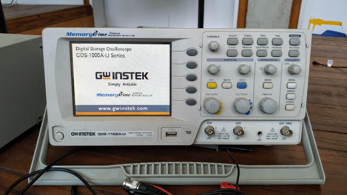
Using an Oscilloscope:
An oscilloscope can graph an electrical signal as it varies over time. Most scopes produce a two-dimensional graph with time
on the x-axis and voltage on the y-axis.
It gives you a view into the electrical waveforms in your circuitry which can not be debugged with a multimter such as communication errors,
PWM wavelength checking and all that.
Luckily Sparkfun has a video on Oscilloscope basics as well, which is very informative.
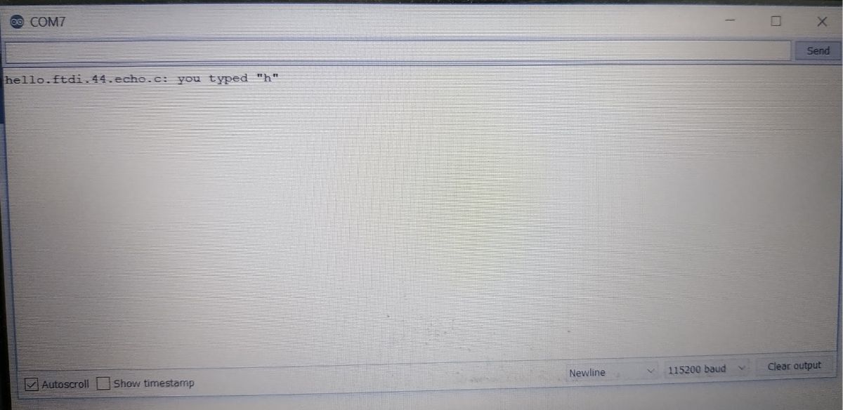
For our Test purpose, we will try to capture the Tx and Rx bits for Neil's Hello Echo code.
But Before that, we need to calibrate our scope.
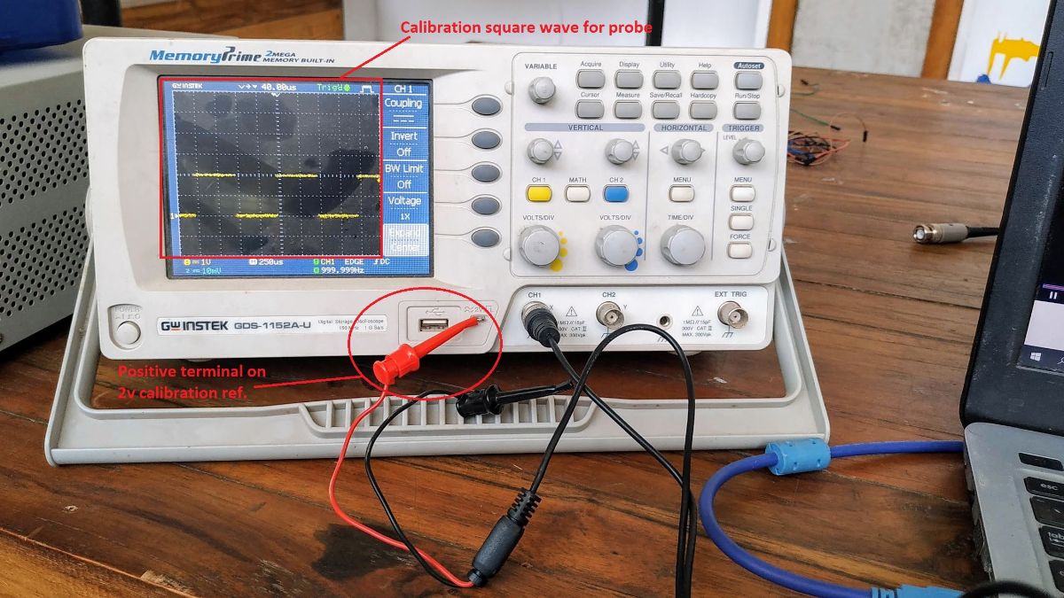
Oscilloscope Calibration:
Calibrating your oscilloscope for the probe you're using is the first thing you'd want to do. In our case, Calibration is done by connecting the positive terminal with the 2v calibration reference connector. It should generate a square wave on the display. Use the channel voltage knob, Horizontal and vertical knobs to align the square wave until it's nicely visible. It should look like this after calibration.
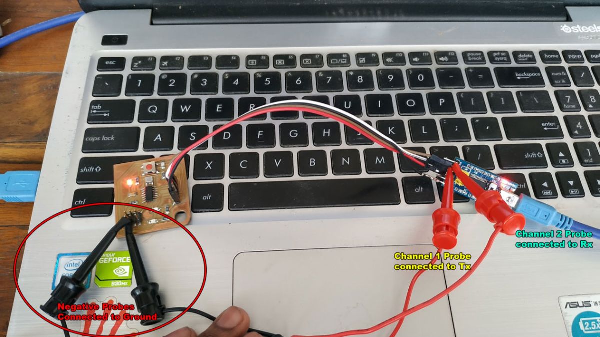
Connecting the Probes to the Circuit:
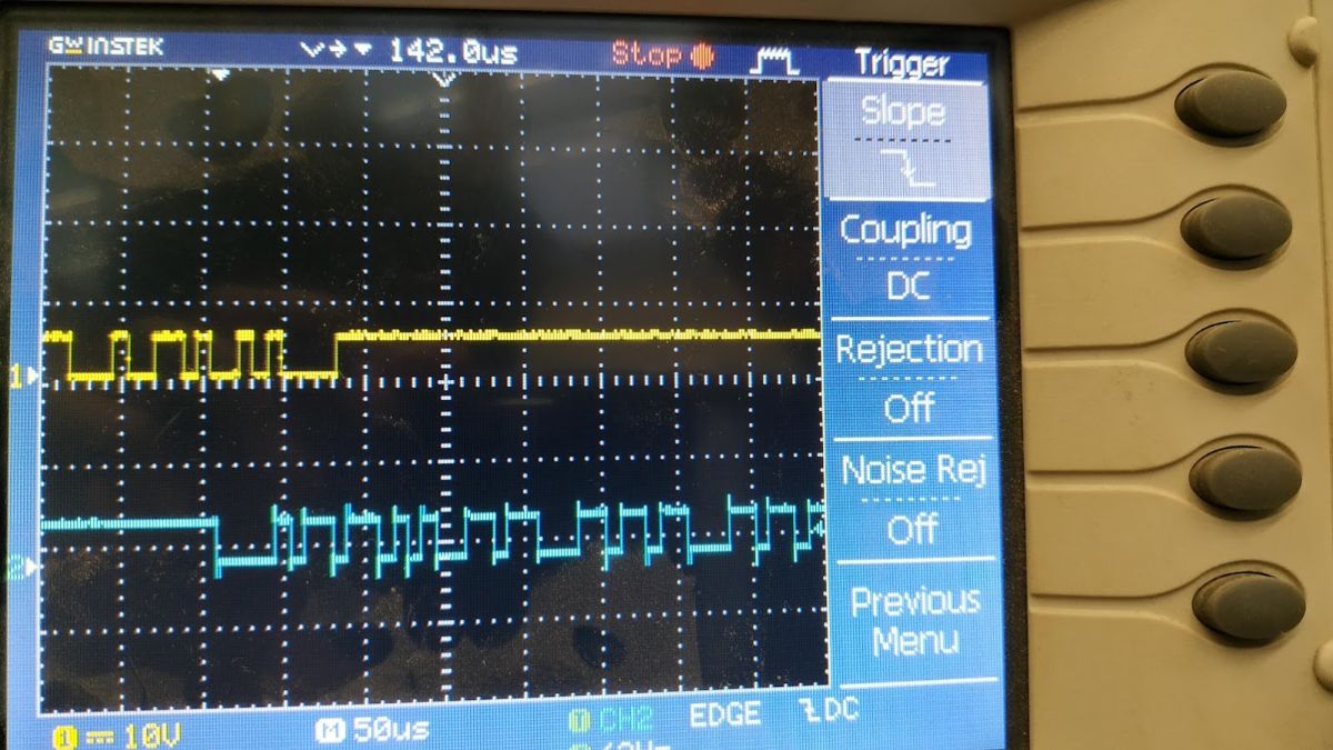
To connect the probes to our hello-echo board, we connected channel 1 to the Tx in the FTDI module, chanel 2 to the Rx in the FTDI module and the GND for
both probes to a GND pin.
Hello Echo Circuit ------------------------ Oscilloscope
Tx line-----------------------------------------Channel 1 probe - positive
Rx line-----------------------------------------Channel 2 probe - positive
GND---------------------------------------------Both Channel 1 and 2- negative
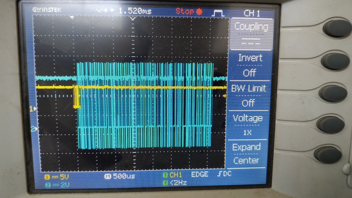
Captured Data:
To capture the data, we need to set the trigger voltage to be a bit lower than 5v, and press the single button on the scope. This will take a reading only when the trigger occurs and stop reading further data. This is done because the data transmission too fast and we need to capture an exact moment to see the bytes.