Week 12: Output Devices
2019.04.03
Individual Assignments:
- Add an output device to a microcontroller board you've designed and program it to do something. Incomplete
Group Assignments:
- Measure the power consumption of an output device. Incomplete
Week 12 Contents:
Charlieplexing
Efficient I/O
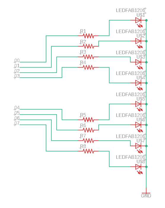
Charlieplexing is a multiplexing technique invented by Charlie Allen. It was created to lower the amount of I/O lines required. On the ATtiny44 there are 14 pins. VCC and GND immediately discount two pins, so we have 12. The MOSI, MISO, SCK and RESET pins can be used as outputs, but are used for the ISP, so we are down to 8 pins. How many LEDs can I drive with 8 pins?

If I just wired each LED to a pin I would use 8 pins to drive 8 LEDs:
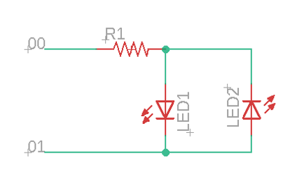
The simplest form of Charlieplexing allows two LEDs to be driven by two pins. There is no I/O saving over just directly driving the LEDs. I drew the following schematic to practice Eagle, but the information is from Best Microcontroller Projects. If 00 is driven HIGH and 01 set LOW then LED1 would light. If the pin voltages were reversed then the other LED would light.
The next step is to add one more pin. This allows control of 6 LEDs using tri-state logic. The three states are HIGH, LOW and INPUT. INPUT is a high-impedence state and does not allow (much) current to flow. This disconnects the pin from the circuit. So by driving the pins connected to an LED to HIGH and LOW and setting all other pins connected to the matrix to INPUT, any single LED can be lit. Rapid cycling of this technique gives the illusion of multiple LEDs being lit.
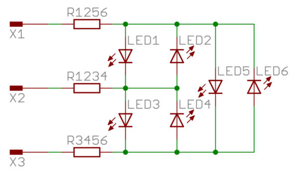 Image credit: Matthiaspaul, CC BY-SA 3.0.
The equation to work out how many LEDs can be controlled is (n)(n-1) where n is the number of pins. For the two LED example above this would be 2 * 1 and the six LED example would be 3 * 2. There is obviously a finite amount of LEDs that can be driven and there are almost certainly some other issues that I am not aware of that will limit the amount of LEDs that can be driven.
Technical Reference
ATtiny44/Arduino Pin-Out Numbering
To make the Charlieplexing attempt easier, I've gathered some technical information that I think I'll need. First of all, the ATtiny44 pin mumbers do not align with the Arduino pin numbers. The following table (taken from the FabAcademy Tutorials) matches up the pins.
| ATtiny44 Pin # | Arduino Pin # | Details |
| 1 | VCC (+) | |
| 2 | Pin 10 | |
| 3 | Pin 9 | |
| 4 | No number, no access? | Reset |
| 5 | Pin 8 | PWM |
| 6 | Pin 7 | PWM, Analog Input 7 |
| 7 | Pin 6 | MOSI, PWM, Analog Input 6 |
| 8 | Pin 5 | Analog Input 5, PWM, MISO |
| 9 | Pin 4 | Analog Input 4, SCK |
| 10 | Pin 3 | Analog Input 3 |
| 11 | Pin 2 | Analog Input 2 |
| 12 | Pin 1 | Analog Input 1 |
| 13 | Pin 0 | Analog Input 0, AREF |
| 14 | GND (-) |
Here's a quick image I drew of the polarity markings on SMD LEDs. There are lots more methods for identifying this, but the ones we have in the lab are covered by these markings.

Logging Data to an SD card
SD card module
The SD card is a 128GB microSD card connected through an SD card module. Note: The SD card has a 3.3v operating voltage, but the module has a voltage regulator and level shifter to allow the use of 5v.
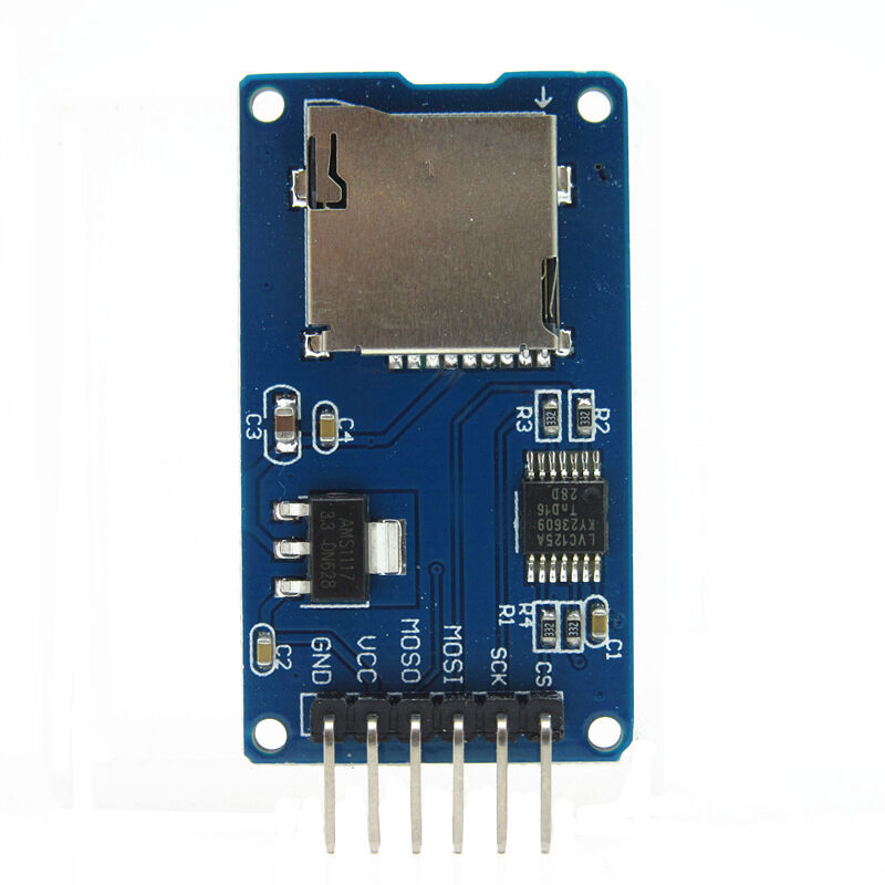 The connection of the SD reader/writer module is quite simple and uses the ISP header pins. There are 6-pins on the module: GND and VCC to power the module, then 4 pins for SPI communication. MOSI (Master Out, Slave In, marked as MOSO on this particular module), MISO (Master In, Slave Out), SCK (serial clock) and CS (chip select in place of slave select). The printing on the module is slightly wrong, but it's easy to work out what they meant.
According to the Arduino site the "Serial Peripheral Interface (SPI) is a synchronous serial data protocol used by microcontrollers for communicating with" peripherals or other microcontrollers (Arduino, 2019). It looks similar to the ISP (In-System Programming) pins (VCC, GND. RST, MOSI, MISO, SCK) but they are not the same. The SPI connection always has "one master device (usually a microcontroller) which controls the peripheral devices" (Arduino, 2019). The MISO, MOSI and SCK are the same on each device. The SS (slave select) line changes per device (the master enables or disables specific devices). "When a device's SS pin is LOW, it communicates with the master. When it's HIGH it ignores the master" (Arduino, 2019).
The respective Arduino pins are:
| Module Pin | Abbreviation | Arduino Pin |
| Clock select | CS | 10 |
| Serial clock | SCK | 13 |
| Master Out, Slave In | MOSI | 11 |
| Master In, Slave Out | MISO | 12 |
Formatting
Formatting the SD card needs to be done correctly for the Arduino to recognise the SD card. Windows will format anything above 32GB as exFAT - the Arduino can't read this. The card needs to be formatted as FAT32. The file names can only be 8.3 (example8.txt) else the Arduino returns errors. I don't usually say this, but I prefer to force the formatting in Windows Powershell - it is a lot easier than Linux fdisk which has way more control, but I don't really want it!
- Windows 10: Right click the Start button or press Win+X.
- Open PowerShell as admin.
- Use
format /fs:fat32 D:(replace D with whatever disk letter your SD card has been assigned by Windows).
Programming
The code opens a file object, starts serial comms and opens the stream to the SD card. There are lots of messages to explain what is going on - this is useful for debugging. In this demo version of the code I am just writing "this is the first line" and "this is the second line" to test that it works. In the final code I will write the data points from the displacement sensor. The code below is based on what I learnt watching this tutorial and this tutorial.
#include <SD.h>
#include <SPI.h>

// Define the file object
File myFile;

// Set the chip select pin
int pinCS = 10;

void setup() {
// Start the serial communication
Serial.begin(9600);
pinMode(pinCS, OUTPUT);

// SD card init
if (SD.begin())
{
// Message
Serial.println("SD card is ready to go...");
} else
{
//Message
Serial.println("SD card initialisation failed.");
return;
}

//Create the file
myFile = SD.open("data.txt", FILE_WRITE);

if (myFile) {
// Message
Serial.println("Writing to file...");

// Write to the file (data from sensor goes here)
myFile.println("This is the first line.");
myFile.println("This is the second line.");

// Close the file
myFile.close();

// Message
Serial.println("Done.");
}
else {
// Message
Serial.println("Error opening file.");
}

// Read the file
myFile = SD.open("data.txt");

if (myFile) {
// Message
Serial.println("Read from file:");

while (myFile.available()) {
Serial.write(myFile.read());
}
myFile.close();
} else {
// Message
Serial.println("Error reading file.");
}
}

void loop() {
}
References
Online
- How Charlieplexing Works [Accessed 04 Jun. 2019].