Week 9: Embedded Programming
2019.03.13
Individual Assignments:
- Read a microcontroller datasheet (ATTinyx4A datasheet). Complete
- Program your board with as many languages/environments as possible. Complete
Group Assignments:
- Compare the performance and development workflows for other architectures. Partially Complete
Week 9 Contents:
- What I learned this week:
Embedded Programming: Method A
Programming my board using C and avrdude
This is my echo.hello_world board remake. In this picture it was not programmed, but the board has a six core ribbon cable attached to the ISP header ready to start... Or so I thought.
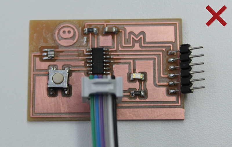
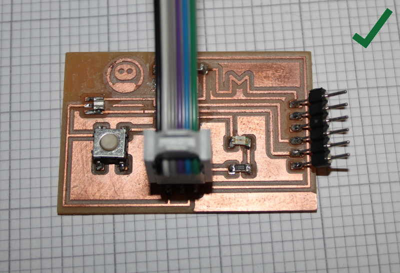
Actually the cable goes on this way, which doesn't make for such a nice picture, but it does work!
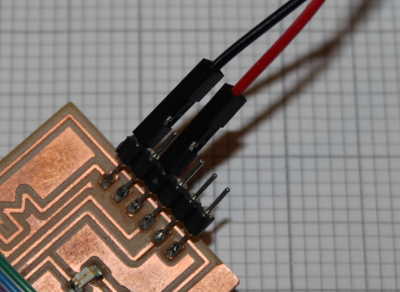
The next thing I did was power the board via the FTDI header. I am using jumper cables from GND (black) and VCC (red) on an Arduino plugged in to my PC. The Arduino is not involved in the programming at all, it's just a convenient means to provide 5V power here at home where I am without a power supply. I plugged the Arduino in to my PC to keep it away from the programming that I'm going to do on the laptop.
The programmer will be plugged in to a USB port on my Linux laptop - this will be used for both powering the programmer and transferring data. The other end of the ribbon cable shown in the first pictures of the board links the programmer to the board via the ISP headers on both PCBs.
To start the programming, I needed a program. I typed a very quick "Hello, world" C program and saved it as '020.testing.c'.

The following few commands are testing the 'Hello, World' program. There is a screenshot of the sequence and output in my terminal after the commands. First I checked that gcc (GNU C Compiler) was installed by using:
$ gcc --version
Once a C program has been written (in any text editor) the command for compiling a C program is:
$ gcc 020.testing.c -o 020.testing
The above line specifies the .c file, then using the -o (output) switch also specifies an output file. In the screenshot below I ran a list command just to see the new file in the directory. Then finally, to run the compiled program, I used:
$ ./020.testing
The output from the program is shown in the terminal, in this case:
Hello, World!
Here's the sequence of commands with the output from my terminal. The output from gcc shows it is installed and gives the version information. When the compiler runs there is no output beyond the creation of the file. Then, once the program is compiled it is run with a dot-slash (./) prefix.

Once I was happy that gcc was installed and working I checked the other two things I'll need to program the AVR chip: avr-libc and avrdude. On my Ubuntu laptop all three were already installed, but if required the following command would install all three:
$ sudo apt-get install gcc-avr avr-libc avrdude
I then plugged the programmer board in to my laptop. The image below shows the programmer:
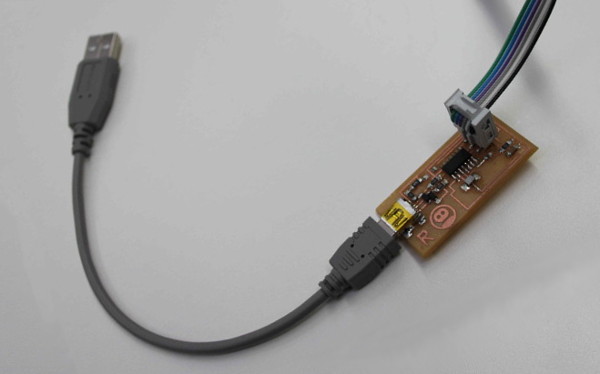
I then connected the board to the programmer, ready for testing. The black USB micro cable is plugged into my PC to provide power to the Arduino, which in turn passes the voltage on to the echo board via the FTDI header. The ISP header is connected to the programmer which is in turn connected to the laptop via USB to receive the data from avrdude (and power the programmer):

The dmesg command displays messages from device drivers. Short for 'driver message' the command shows the messages the driver generates when the USB device is plugged in. To run it, simply type:
$ dmesg
The top line below shows me disconnecting my programmer, then the lines below are the messages given when I plug it in again:
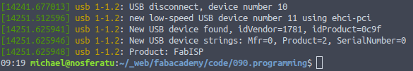
The next command also shows information about the USB devices connected to the system:
$ lsusb
The command lists USB devices. The output from my machine showing the programmer connected is:
Bus 003 Device 003: ID 1781:0c9f Multiple Vendors USBtiny
So, as far as Linux is concerned the programmer seemed to be working. It reported itself to the system as seen above. Now to consider the ribbon cable that connects the board to the programmer: I don't totally understand what these pins do (apart from the general conception that it is a serial communciation method) so the table below just holds what I understand so far. The ISP header pinout looks like this:

| PIN | Abbr | Meaning | Description |
| 1 | MISO | Master In Slave Out | Data output from the slave (board to be programmed) |
| 2 | VCC | Voltage Common Collector | Not a way to power the board! |
| 3 | SCK | Serial Clock | Signal that sets the timing for the serial communication. The side that generates the clock signal is called the 'master'. |
| 4 | MOSI | Master Out Slave In | Data output from the master (programmer) |
| 5 | RST | Reset | Does what it says on the tin. |
| 6 | GND | Ground | The 0V pin. |
Here's the ATtiny44 pinout. The button is connected to pin 6/PA7 and the LED is connected to pin 11/PA2 on the ATtiny44. The PA numbers are the ones to use in the program:

Programming the board
Here's a very simple blinker program - it just pulls pin PA2 high and low with a delay. I have just pulled parts of the program that Neil shared on the schedule.
				// Very simple blinker

				#include <avr/io.h>


				// F_CPU defines the frequency of the CPU. 1e6 is 1x10^6 or 1MHz.

				// It must be defined to give a value for the following include.

				#define F_CPU 1e6


				#include <util/delay.h>


				int main()

				{

				DDRA = _BV(PA2);

				PORTA = _BV(PA2);


				while (1)

				{

				PORTA = _BV(PA2);

				_delay_ms(1000);

				PORTA = 0;

				_delay_ms(1000);

				}

				}
I need to get this program on to the microcontroller on the board. There are three parts to the programming using the three items we installed earlier (gcc, avr-libc and avrdude):
- Compile a .BIN file from the .c file
- Convert the .BIN to a .HEX file
- Flash the .HEX file to the AVR chip
1. Compile
I saved the blink program above as blink.c - the following line creates a compiled binary from that file specifically for the ATtiny44:
$ avr-gcc -Wall -g -Os -mmcu=attiny44 -o blink.bin blink.c
Using the following command I checked the size of the binary:
$ avr-size -C blink.bin
This gives the following output, showing that the program is 104 bytes:
				AVR Memory Usage

				----------------

				Device: Unknown


				Program:      104 bytes

				(.text + .data + .bootloader)


				Data:          0 bytes

				(.data + .bss + .noinit)
2. Convert
I then converted the binary into a .HEX file using:
$ avr-objcopy -j .text -j .data -O ihex blink.bin blink.hex
This creates a new blink.hex file in the directory.
3. Flash
Finally I flash the program to the chip using:
$ avrdude -p attiny44 -c usbtiny -U flash:w:blink.hex:i -F -P usb
The -p switch is for 'part' and attiny44 is specified. The -c is the programmer, in this case usbtiny.
The output from avrdude:
				avrdude: AVR device initialized and ready to accept instructions


				Reading | ################################################## | 100% 0.00s


				avrdude: Device signature = 0x1e9207 (probably t44)

				avrdude: NOTE: "flash" memory has been specified, an erase cycle will be performed

						 To disable this feature, specify the -D option.

				avrdude: erasing chip

				avrdude: reading input file "blink.hex"

				avrdude: writing flash (104 bytes):


				Writing | ################################################## | 100% 0.06s


				avrdude: 104 bytes of flash written

				avrdude: verifying flash memory against blink.hex:

				avrdude: load data flash data from input file blink.hex:

				avrdude: input file blink.hex contains 104 bytes

				avrdude: reading on-chip flash data:


				Reading | ################################################## | 100% 0.07s


				avrdude: verifying ...

				avrdude: 104 bytes of flash verified


				avrdude: safemode: Fuses OK (E:FF, H:DF, L:62)


				avrdude done.  Thank you.
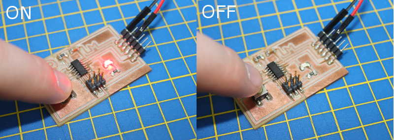
Success! Once the hashtag bars filled up and avrdude gave the 'done. Thank you.' message, the red LED starting flashing immediately.

Below is a video showing the very basic C program in action, just flashing the LED every 1000 ms. I need to work out how to take input from the button now...
Downloads (Programming the ATtiny44 with C)
Embedded Programming: Method B
Programming the ATtiny44 with the Arduino IDE
I am using Ubuntu 18.04 on my laptop. Ubuntu is using Snappy as a package management system as well as apt. The version of Arduino in the main respository is old, but the Snap version is 1.8.5, much newer. The problem is that, by default, there is no permission to use the serial ports. I tried a few of the standard remedies for this problem - added myself to the 'dialout' group and tried various chmod operations on /tty/ACM0, but to no avail. It was then that I noticed a 'permissions' button in the software centre on the Arduino Snap page. It doesn't do anything much at the moment on the desktop version, but apparently is due to be brought into use in the future. It didn't solve my problem, but it led me to the solution: The Arduino Snap can be installed in 'developer mode' with a --devmode switch.
$ sudo snap install arduino-mhall119 --devmode
Now the Arduino IDE has access to the serial port!
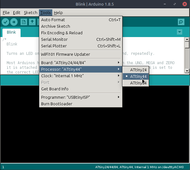
The next step is to get the ATtiny support installed for the IDE. I followed the instructions at High/Low Tech here. The instructions there are comprehensive, but the only bit I really needed was the boards manager section. To find it in the Arduino IDE choose File > Preferences and then at the bottom of the dialogue there is a field for 'Additional Board Managers URLs'. Paste the following URL into that field:
https://raw.githubusercontent.com/damellis/attiny/ide-1.6.x-boards-manager/package_damellis_attiny_index.json
Then I opened the board manager (at the top of the Tools > Board list) and found the ATtiny panel. I clicked install and it now looks like this:

Once the ATtiny support is installed the ATtiny boards appear in the Tools > Board list. I selected the ATtiny24/44/84 option. Then set the rest of the settings as per the image below (ATtiny44, 1Mhz, USBtinyISP):
The hardware is set up exactly the same as it was before - programmer plugged to the laptop, ribbon running from programmer to board via the ISP headers, power for the board through the FTDI header from the Arduino and the Arduino just supplying power (plugged in to PC).
I wrote an Arduino sketch to take input from the button. This just turns the LED on when the button is pushed. The button is connected to pin 7 as far as Arduino is concerned.

Morse Code
The final program I wrote this week displays the Morse Code for 'MICHAEL' when you press the button:
_ _ > . . > _ . _ . > . . . . > . _ > . > . _ . .
I made three functions: dash, dot and wordGap. Then made functions for each letter. The video below is a the program running on an Arduino simulator - I've switched on every LED I could find to make it obvious.
Here's the real board in use:Downloads (Programming the ATtiny44 with Arduino IDE)
ON/OFF: 090.arduino_button.ino (<1KB)
Morse Code: 090.arduino_button_function.ino (<2KB)
Datasheet
ATtiny44
The ATtiny44 datasheet explains everything you need to know about the 'universe' inside the AVR chip. I have to confess, I do not understand a great deal of what the datasheet says at the moment, but I'm trying to lay a foundation for understanding and have picked out some of the system functions that I read about.
Pin Descriptions
The first section describes the pins. The 'package' we are using is the SOIC (Small Outline Integrated Circuit) which is a surface mount IC (Integrated Circuit) as opposed to a through-hole DIP (Dual In-Line Package). The names for the Small Outline packages are usually identified with SOIC or SO prefixed or suffixed with the amount of pins. In the case of this AVR ATtiny44 it is identified on digikey.co.uk as '14-SOIC'. There are two ports: A and B, which make up 12 of the pins (8 for A and 4 for B). The last two pins are VCC and Ground.
| VCC | Supply voltage |
| GND | Ground |
| PB3:PB0 | Port B has 4 input/outputs with internal pull-up resistors. There are alternate port functions too. |
| RESET | Reset input - a low level on this pin for longer than than minimum pulse length will generate a reset. |
| PA7:PA0 | Port A is an 8-bit I/O with internal pull up resistors. |
Pull-up/Pull-down Resistors
Pull-up or pull-down resitors are used to stop 'floating' (indeterminate) voltages on a particular pin. The resistor pulls the voltage up or down to either high or low respectively. On the ATtiny44 the pull-up resistors are built in to the MCU to cut down on the amount of external components that are required.
Power Management and Sleep Modes
The chip has different sleep modes: Idle, ADC Noise Reduction, Power-down and Stand-by. You can set a bit in the MCUCR register to select a sleep mode. An interrupt is used to wake the MCU.
C Programming
Starting out with C
I'm going to cover the basic input, output, selection and iteration commands that should be enough to write basic programs.
Testing the C installation
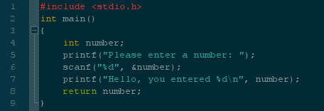
I took the really simple "Hello, world" C program I wrote earlier for testign the gcc. It is saved as '020.testing.c'.
The <stdio.h> line tells the compiler to include a common header (.h) file, 'stdio.h', when it compiles. The file name is short for 'standard input/output' and provides code for getting input and outputting (printing) to the terminal.
The void main() block (punctuated with {}) is the main function. The 'void' just means that the function won't return anything. Any arguments for the function would go in the round parentheses.
The printf function prints 'Hello, world!' to the screen. The '\n' is a carriage return.
I know the gcc compiler is installed and working as I used it earlier, but if I needed to check I could use:
$ gcc --version
I then compiled the "Hello, World" program. The following line invokes gcc and selects the '020.testing.c' file, compiles it and outputs (-o) as '020.testing'.
$ gcc 020.testing.c -o 020.testing
A quick ls shows that we now have two files - the original .c and the compiled program. To run the code use:
$./020.testing
C needs explicitly declared variable types. Some common data types include: int, char, short, long, float, double. To declare a variable:
int x = 15;
This declares a variable of type 'int' called 'x' and sets it to '15'.
Input
The next step is to take input:
Arduino IDE and LEDs
Playing around with programming an Arduino
I really loved using the Arduino IDE, so I got a bit distracted using a breadboard to play around with various LED flashing programs for the Arduino.
LED polarity
LED stands for Light Emitting Diode. As a diode LEDs have a polarity. Current can only flow through them in one direction, so the orientation of the LED is important. To determine which way to place the LED you can look at the legs. The long leg is the annode and the shorter one is the cathode. A mnenomic is PANIC: Positive is Annode, Negative Is Cathode.

It is also possible to determine the polarity from the lens/casing of the LED. The LED will have a flat edge on the casing, visible from the top – the flat edge is the negative side (cathode). LEDs require resistance to protect them from excess current. Resisters do NOT have a polarity so can be placed in any orientation. Without the resistor the LED would burn a bright, but very short life, very quickly becoming useless!
Arduino Prototype
There is a built in example called 'blink' in the Arduino IDE that shows the code for flashing an LED on and off. While playing with that I stumbled upon using a pin LOW as GND and a pin HIGH as VCC and I tried 2 LEDs wired in opposition to the same pins, lighting one or the other by pulling the pins LOW and HIGH. The video below shows the code running, pulling one pin high and the other low, then vice versa:
I've been thinking I could use LEDs to teach binary numbers to my high school students, so I wired up four LEDs to be able to show 4-bit binary numbers. To make the LEDs show a 4-bit binary number I wrote a function for each number, then just set four pins either HIGH or LOW.
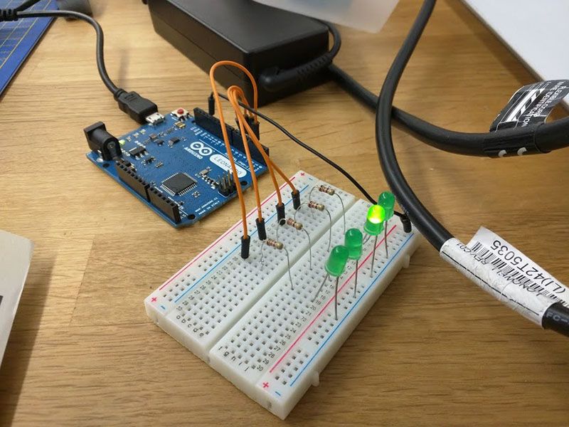
Now in full distraction mode, I programmed a binary counter. The LEDs in the video below are representing binary numbers from 0-15.
Getting a Shift On
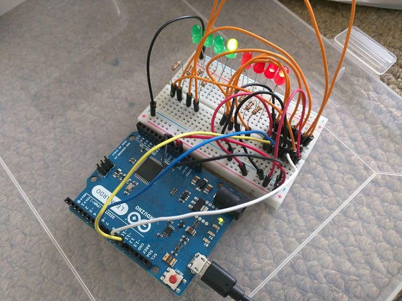
In my now indispensable 'Arduino's for Dummies' book (Nussey, 2013) I discovered shift registers. The one I have is a SN74HC595N which is described in the book (and the data sheet) as an "8-bit serial in, serial or parallel-out shift register with output latches; 3 state". As I understand it, this means I can send an 8-bit binary number over serial which the register will then output as parallel on 8 pins - allowing me to control 8 LEDs with only three (I initially thought two) pins. With a single ATTINY44 and two shift registers, I can control up to 16 LEDs using 6 pins.
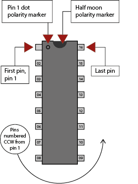
Pin Numbering
The shift register needs to be placed the correct way around. Figure A is a quick reminder of the most common ways to orientate a chip (Oskay, 2018) - the half moon notch or the dot showing the corner which holds pin 1. The pins are then numbered counter-clockwise with the last pin level with the first.
Figure B and the accompanying table shows the number and names of the pins. The table below describes the functions of the pins.
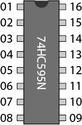
| # | Name | # | Name |
| 01 | Q1 | 16 | VCC |
| 02 | Q2 | 15 | Q0 |
| 03 | Q3 | 14 | DS |
| 04 | Q4 | 13 | OE |
| 05 | Q5 | 12 | STCP |
| 06 | Q6 | 11 | SHCP |
| 07 | Q7 | 10 | MR |
| 08 | GND | 09 | Q7' |
The Shift Register Pins
| Pin | Description | Use |
| Q0-Q7 | Output pins | Connected to the LEDs. |
| GND | Ground | Linked to GND on Arduino. |
| Q7' | Serial Out | Used to shift data to another 74HC595. |
| MR | Master Reclear, active low | This clears the shift register if pulled LOW. |
| SH_CP | Shift register clock plink | If pulled HIGH this shifts all the values forward one. |
| ST_CP | Storage register lock pin (latch pin) | When pulled HIGH (must be done straight after SH_CP goes LOW again) it outputs the new shift register values. |
| OE | Output Enable, active low | This enables the output when grounded and disables it when HIGH. |
| DS | Serial data output | This is the input pin for the new serial data. |
| Vcc | Positive voltage supply | This is the voltage supply for the LEDs. |
Shift Register Summary
The maximum number for 8-bit (1 byte) binary number is 255. This is 11111111 in binary. If you send this number then all outputs go to HIGH. If you send 10101101 then pins 0,2,3,5 and 7 go HIGH. You can cascade the 74HC595s using Q7'.
int latchPin = 8;

int clockPin = 12;

int dataPin = 11;


void setup() {

  pinMode(latchPin, OUTPUT);

  pinMode(clockPin, OUTPUT);

  pinMode(dataPin, OUTPUT);

}


void loop() {

for (int numberToDisplay = 0; numberToDisplay < 256; numberToDisplay++) {

  digitalWrite(latchPin, LOW);

  shiftOut(dataPin, clockPin, MSBFIRST, numberToDisplay);

  digitalWrite(latchPin, HIGH);

  delay(1000);

  }

}


// From 'Arduino's for Dummies' (Nussey, 2013)
Program highlights, with comments:
// Used to output the values from the register (release the latch)
int latchPin = 8;
// Used to 'shift' the values along by one
int clockPin = 12;
// Used to send new data to the register
int dataPin = 11;
// Set all the pins to OUTPUT.
				pinMode(latchPin, OUTPUT);

				pinMode(clockPin, OUTPUT);

				pinMode(dataPin, OUTPUT);
// Set the latchPin LOW, so that it doesn't output the register values while I change them.
digitalWrite(latchPin, LOW);
// The shiftOut function is built in to Arduino IDE, it requires 4 parameters (dataPin, clockPin, MSBFIRST/LSBFIRST, numberToDisplay). MSBFIRST/LSBFIRST means Most Significant Bit FIRST or Least Significant Bit FIRST. The function takes the value (numberToDisplay) and handles all the pulses to convert it to a combination of pins that fills the buffer.
shiftOut(dataPin, clockPin, MSBFIRST, numberToDisplay);
// Set the latch pin HIGH again to output the data.
digitalWrite(latchPin, HIGH);
Downloads (FabModules)
Obstacles
Floating point rounding
I have to admit I was thoroughly confused by this problem. I was trying to change the binary counter to create a Knightrider style K.I.T.T. car LED wave. To display this I wanted to count in the numbers that light the individual LEDs: 1, 2, 4, 8, 16, 32, 64, 128. When these light up in sequence the LED looks like it is moving from one side of the array to the other. When I finally sorted it out it looked like this:
The desired sequence is 2^1, 2^2, 2^3, 2^4, etc. I assumed I could use 2^n in the code, but apparently C considers ^ as the symbol for XOR. There is a function pow(base, exponent) which provides a floating point. This is where the severe confusion began...
The numbers I was getting out of the pow() function just weren't making sense: it counted 1, 1, 3, 7, 15, 31, 63, 127. After half an hour of checking and rechecking and reading various numbers out of the code, I stumbled upon some pertinent information on floating point rounding errors. The pow() function uses floats rather than integers. After falling down this particular rabbit hole, I can report: infinite real numbers cannot be properly represented in finite computer memory and rounding errors occur. With the tiny numbers I am dealing with I can add 0.5 to force the numbers to round up. The following statement fixes my issue:
int power = 0.5 + pow(base, exponent);
While researching the pow() function I came across the concept of shifting, which is basically moving bits into the next column of a binary representation. So a 1 in the 1 column shifts left to the 2 column. This can be coded like: 1 << 3. This would shift the bit into the 8 column. This code is more efficient because there is no multiplication being carried out.
Here is the full code:
int latchPin = 8;
int clockPin = 12;
int dataPin = 11;

void setup() {
  pinMode(latchPin, OUTPUT);
  pinMode(clockPin, OUTPUT);
  pinMode(dataPin, OUTPUT);
}

boolean wave = true;
void loop() {
  for (int numberToDisplay = 0; numberToDisplay < 8; numberToDisplay++) {
    int power = 1 << numberToDisplay;
    digitalWrite(latchPin, LOW);

      if (wave == true) {
        shiftOut(dataPin, clockPin, MSBFIRST, power);
      } else {
        shiftOut(dataPin, clockPin, LSBFIRST, power);
      }

    digitalWrite(latchPin, HIGH);
    delay(50);
  }
  wave = !wave;
}
References
Offline
- The Fab Charter [Accessed 30 Mar. 2018].
Offline
- Donat, W. (2018). Make: Jumpstarting C. 1st ed. O′Reilly.