Week 6: 3D Scanning and Printing
2019.02.20
Individual Assignments:
- Design and 3D print an object (small, a few cm) that could not be made subtractively. Complete
- 3D scan an object (and optionally print it). Complete
Group Assignments:
- Test the design rules for your 3D printer(s). Incomplete
Week 6 Contents:
- What I learned this week:
- Obstacles and Solutions
- Downloads
- References
3D Printing
Overview
This week we are creating 3D printed models using CAD to generate a model and then the Creality CR-10 to 3D print using PLA. I have seen lots of 3D printed parts before, at various demonstrations or shows (Mini Maker Faire in Brighton), but I have never printed anything myself, so this is all very new. I understand the basic principle of building by layers and the associated issues with overhangs and detail, but a basic understanding of it compared to real-life experience are two very different things...
I have also practised CAD this week, trying a few different features in the modelling software by cutting shapes and patterning items. The shapes I have built would be hard to make with subtractive methods. If I were to mill the rocket from a solid block the machine would need more than the X, Y, Z axes of our CNC machine. The tool would not be able to access certain parts of the model (for example, around the fins and the exhaust). It would be possible to create a layered version of this from slices of lasercut material, but the process would be labourious and would require gluing or joining of the pieces. The additive manufacturing method produces a part with mechanical properties more similar to a single piece of material.
The advantages of 3D printing are numerous. As an additive technology, as opposed to subtractive, the process certainly generates less waste (beyond support materials, only what is required is added.
Workflow
Our machine (Creality CR-10) is not connected directly to a computer. There is a micro SD card slot on the control unit and work is transferred by sneakernet from the PC to the printer. The models made in Fusion360 are easy to export to Cura as an .STL file. Once the print settings are finalised, the files are then transferred to the printer.
Cura Settings
When setting up and printing a model there are a few things to think about. In a similar way to setting the DPI, colour and finish of a paper print, the settings will impact the resolution, strength, quality, time and cost of the 3D print.
Model 1: Retro Rocket
The first model is a gaming piece for a boardgame called Tiny Epic Galaxies. Each player commands a number of rockets - the wooden meeple-style pieces included in the game are essentially 2D, relying on the thickness of the wood to give them depth. The main issue here is the size. The original wooden pieces are around 2cm tall. The models could stand to be slightly taller, but not by much. I wanted to push the machine and see what it can produce at smaller sizes.
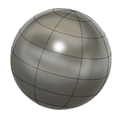
I used the 'Create Form' tool to sculpt the rocket body, starting with a sphere.
I then formed the fuselage using Modify > Edit Form to stretch out the sphere.
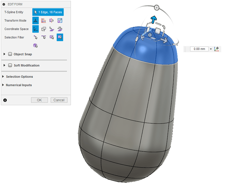
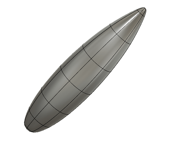
I played around with the 'Edit Form' tool, making selections and dragging parts out until I got a rocket shape I was happy with.
I then used a sketched rectangle as a cutting plane to slice the base of the rocket off.
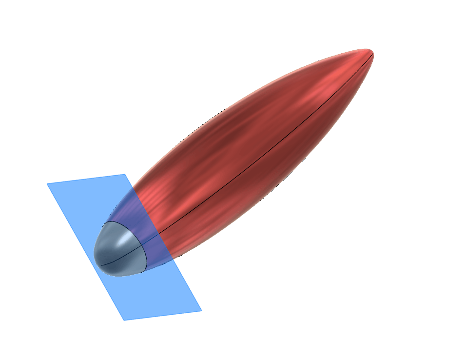
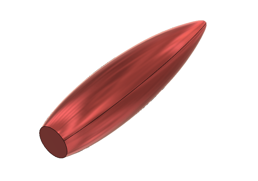
Once the original body was sliced, the two parts appear in Fusion 360 as two separate bodies. I hid the smaller slice.
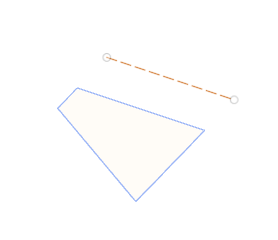
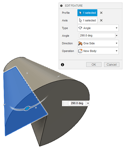
To create the thruster I sketched a shape and used Create > Revolve to make a drafted cylinder. There are other ways to create this shape too.
I then cut a cylinder out from the middle by first creating a circular sketch on the base and cutting it out of the first shape using extrude with a 'Cut' operation on the body.
I then used Modify > Press Pull to get it to a size I wanted.
I then aligned the thruster to the base of the fuselage.
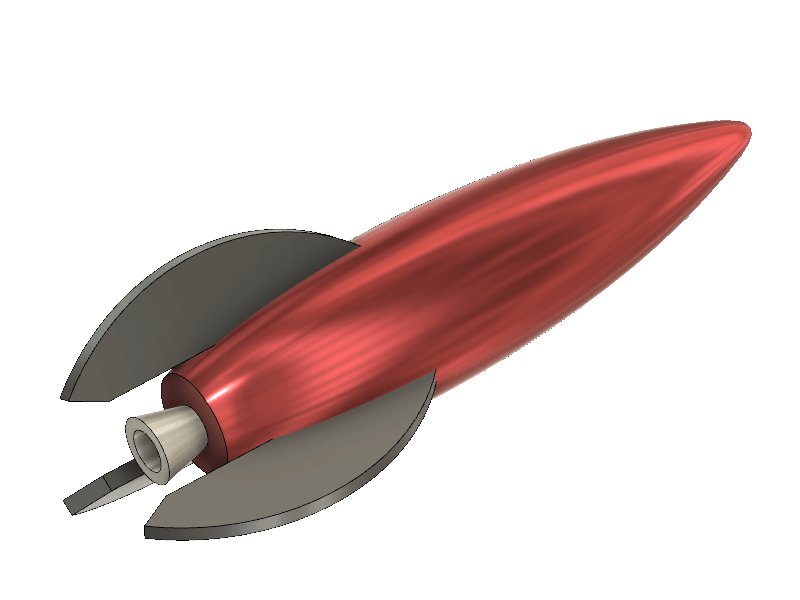
I then sketched a fin/wing, extruded it and moved it in to position. In the the 'bottom' view I used Create > Pattern > Circular Pattern to duplicate the fins around the fuselage.
The suppress option allows you to click on a 'checkbox' next to each pattern item when selected, any checked item will not be patterned.
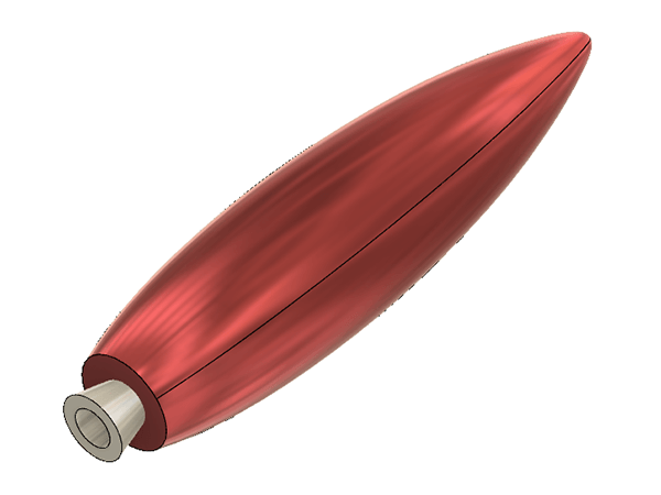
Here is the final model.
Screen capture of the model being orbited in Fusion 360:
I had to edit the model for 3D printing. I considered creating four fins rather than three and slicing the model vertically, then printing the two halves horizontally and gluing them together. In the end I sliced off the bottom of the fins to the level of the thruster, enabling me to print the rocket standing vertically.
In Fusion 360 the process to make a 3D print is to choose Make > 3D Print. This then allows you to select the bodies that you want to send to 'Cura', the 3D printing software. This is where everything came to a grinding halt this week as I could not get everything to export together as an .stl file.
The 3D print output would only let me select one body. One way to create this single unified body from all my bodies was to use Modify > Combine and select all the bodies. This created a new component with a single body. This could then be selected and outputted to an .stl file, at least that was the plan.
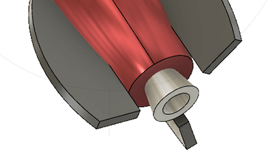
The problem I had was that whenever I tried to create this single component using 'Combine' it was creating two separate bodies. After a lot of head scratching and trying various things I realised that the thruster was not quite touching or overlapping the rocket fuselage, so was being created as a seperate body after the combine operation. I moved the thruster slightly in to the body of the rocket and was then able to combine everything and export the rocket as a single .stl item.
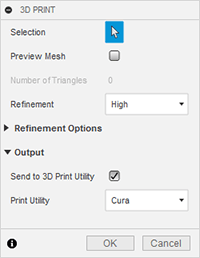
Click on Make > 3D Printer to bring up the dialogue box.
I chose 'Refinement: High' and selected 'Cura' as the 'Print Utility'. Then I clicked on the new component body (the single unified rocket) and pressed [OK] to send the .stl to Cura.
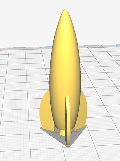
The rocket in Cura once it had been rotated to stand vertically on the bed.
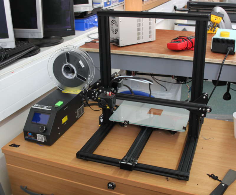
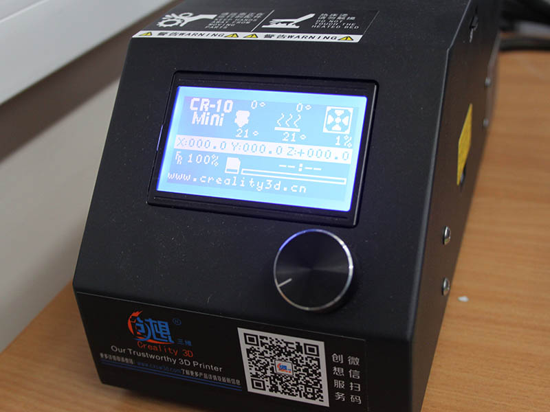
The 3D printer we use in the lab is a Creality CR-10. It's a heated bed, open frame printer.
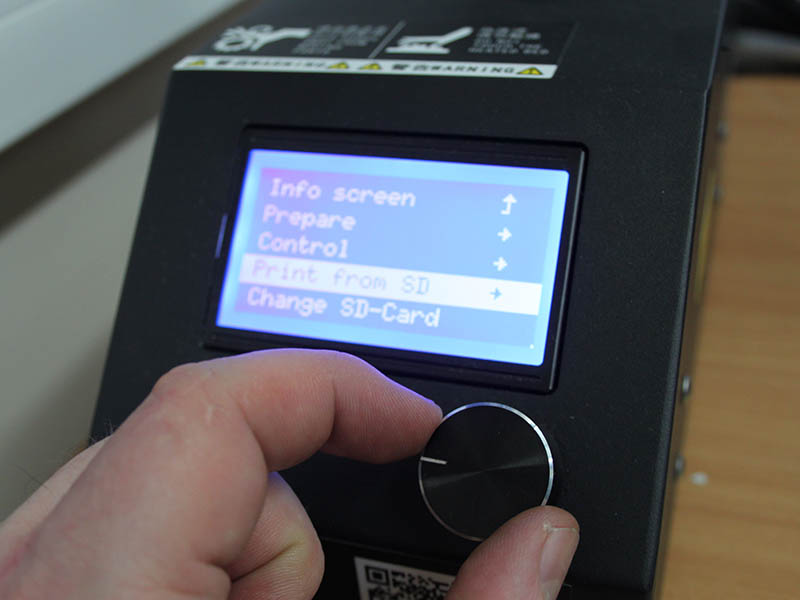
The files are printed from a micro-SD card. Using the USB adapter for micro-SD card, I saved the file to the micro-SD then plugged the SD card into the control unit for the Creality printer.
There was a slight confusion here, as I tried to use the 3D printer on my own and I thought the 'INIT SD' option would format the SD card. In actual fact it initialises it and allows you to see the files on the card. After you click the 'INIT SD' option, you get the 'Print from SD' option. Inside that option the machine displays a file list. I just selected my file. Cura gives the files odd names, but I renamed it 'rocket' for ease of use.
I made two prints of the rocket, one 40mm and one 60mm high with different resolution settings.

This is the 60mm rocket printed at 'Low Quality' (0.15mm layer height) from Cura. The print took 28 minutes.

Model 2: Antique Tap Dimmer Switch Knob
My flat has a dimmer switch for almost every light, but a lot of them are missing the knobs. The only ones I have ever seen are just round (smooth plastic or metal, either white, chrome or a solid colour, but always just a cylinder). I want to make something slightly more interesting. I have an antique/Victorian tap style knob in mind. I really like the organic shapes, but also the craftsmanship beyond utility.

Image from Pexels.com. See references for license.
CAD Model
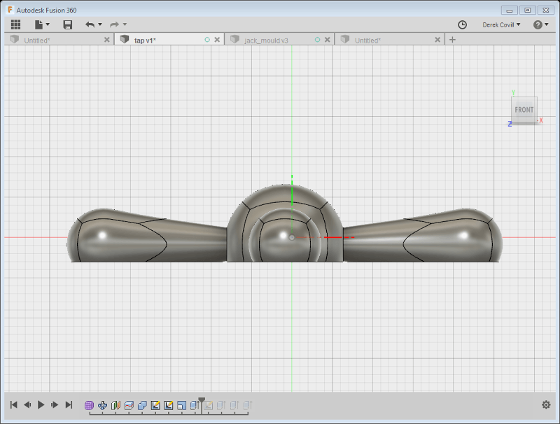
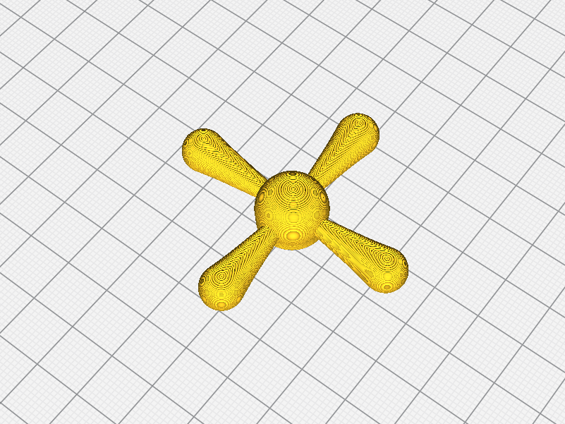
After measuring the boring cylindrical dimmer knob I modeled my brass tap style design in Fusion 360. First I created a 'quadball' and pulled one side out. The organic sculpting in Fusion 360 is very interesting and something I want to explore more. Kyle gave us a great introduction to the sculpting in Fusion 360 in the local recitation. The Fusion workflow is very different to other applications I have used. I generally just start drawing in Illustrator, but with Fusion I definitely needed to think about my parts and the parameters first. Getting some numbers in to the variables before creating any sketches helps a lot when building your model.

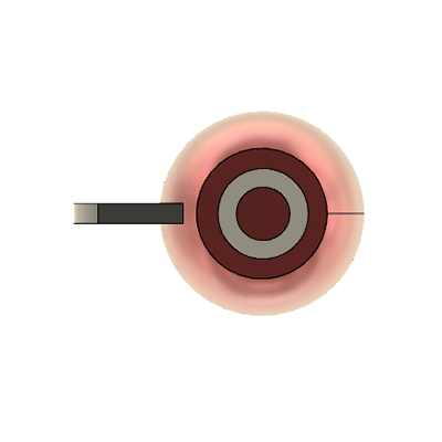
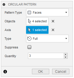
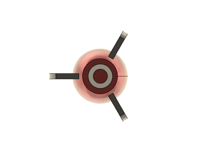
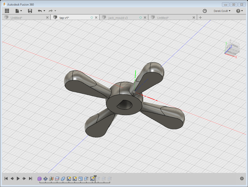
I drew a sphere for the centre part and used Fusion-360 > Model > Create > Pattern > Circular Pattern to duplicate the spline three more times around the central sphere (with Poppy's help!).

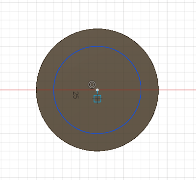
The dimmer knob should not stick out too far, so I am going to slice the bottom of the model off. I want to have a flat base, but leave enough curve under the sphere and the splines, so that this item could not be made with a 'subtractive' process. I will also need an extruded ring around the edge of the central part, but more on that later.

I used a plane offset by a few millimetres to slice through the five bodies, then hid the bottom sections.
The base is now flat.

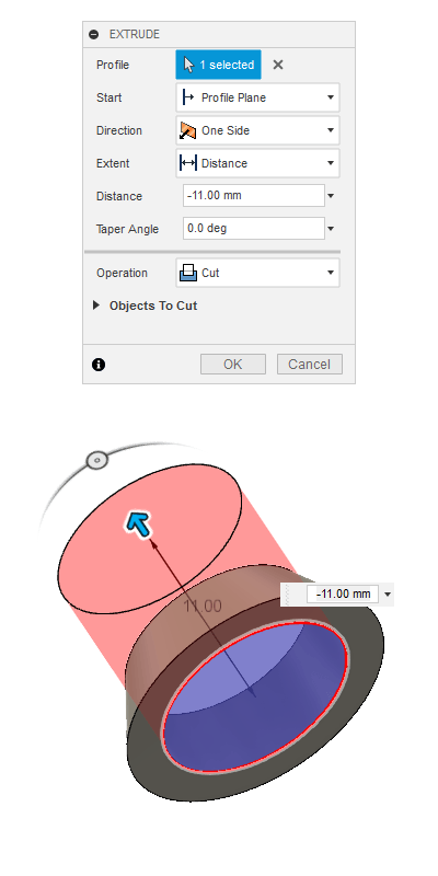
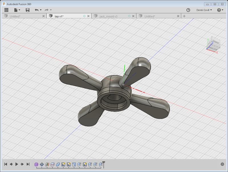
To be able to attach the knob to the switch axle I need a 'D' shaped aperture. The calipers show that this is 6mm diameter, with one edge sliced off to hold the knob in place. The measurement from the curved side to the slice is 4.8mm. I am going to expand these dimensions by .2mm to allow the knob to easily fit the switch axle. I drew, then extruded, the 'D' shaped switch axle aperture. This was extruded -8.75mm into the central part.
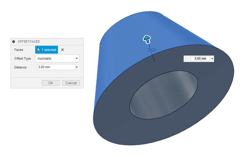
The switch axle has a nut around the base holding the switch axle to the switch plate. This is a bit ugly and the original knob had a slightly longer external casing to hide it somewhat. It can't be too long as the switch is operated on/off by pushing the knob in, but 3mm should be fine.
With the CAD finished I exported the model as an '.stl' file (an abbreviation of stereolithography). I then open the exported file in Ultimaker Cura.
The following image shows the 'brim' style of print I used. This creates a flat base that adheres better to the printing plate and stops the model tipping over during printing.
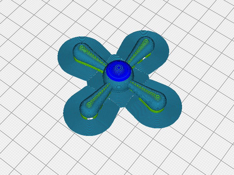
The green portions on the following images are the support structure that Cura has automatically added to make the base flat due to the ring I extruded around the base of the centre sphere.

The following is a custom view in Cura. Removing the 'shell' shows the support material that will fill in the gaps on the underside of the model.

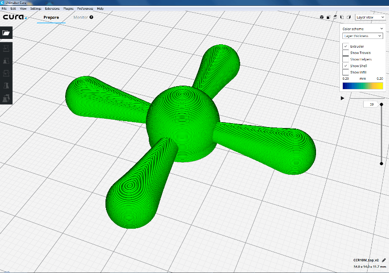
This final Cura image shows the detail of the layers.
The printer is a Creality CR-10 Mini (about £250). It seems to be a reliable machine. I have to admit that I was not very interested in 3D printing until now, but this is partly because of the low quality machines I have witnessed before. They were mostly homebrew machines and seemed to need a lot of maintenance and patience to produce useable prints.
The brim and the infill still attached.
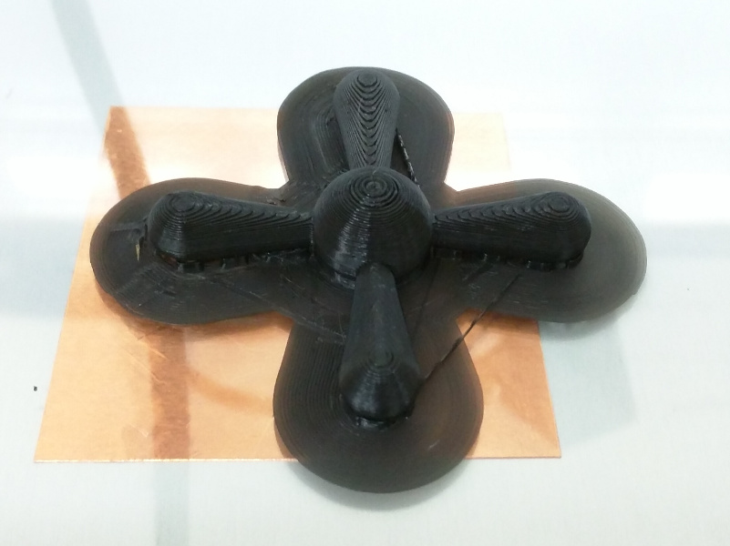
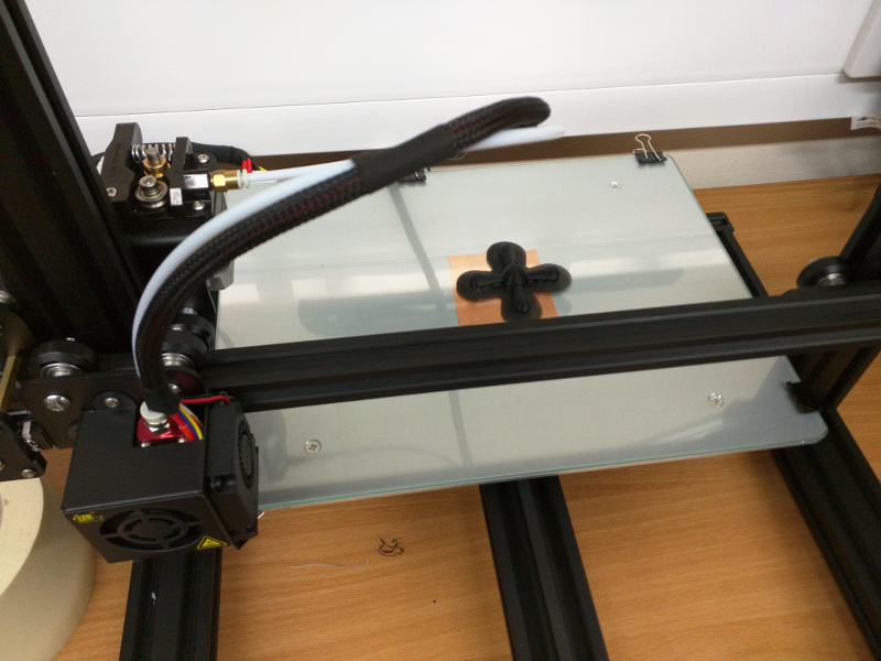
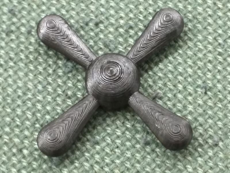
The final piece with support material and brim removed. Most broke off very easily, but I cut the last bits with side cutters. I also pulled the infill out from the the 'D' shaped aperture.
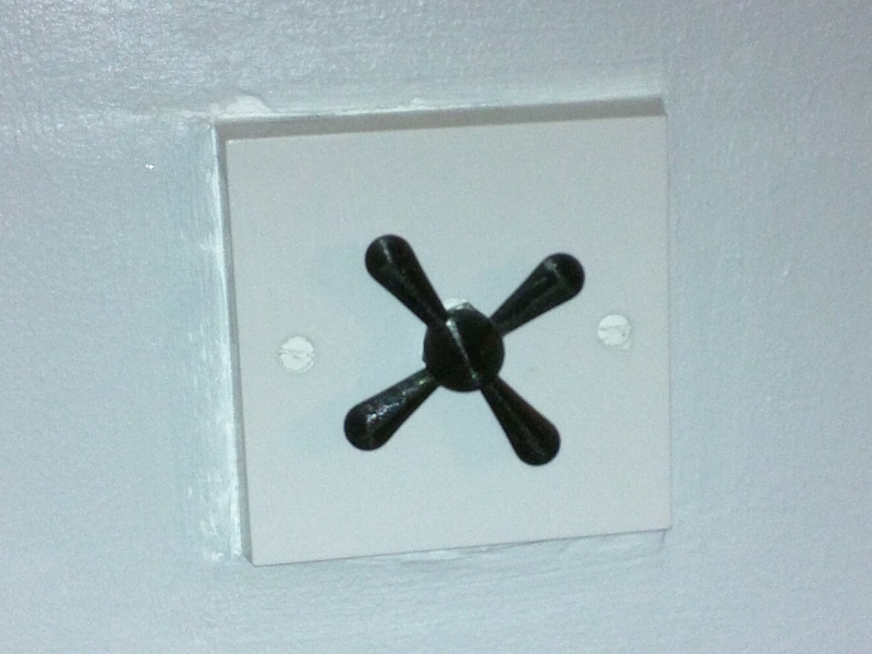
The knob in situ on the switch plate in my flat. The extra .2mm was perfect and the knob fits the axle tightly, but was easy to push on. It is actually slightly better than the mass-produced cylindrical knob I measured.
3D Scanning
Structure Sensor/iSense with an iPad Pro
The 3D scanning in the lab is carried out with a Structure Sensor based product that fits an iPad Pro. To understand how it works I read about 'structured light scanning'. In the simplest terms the device emmits infrared light patterns which are picked up by a camera. The way the light falls across an object enables the camera to determine distance from the scanner and form shapes.
The image below (The Paleontological Society, 2019) shows the deformation of a grid pattern that the camera of a 3D scanner using this method would be able to detect.

The Structure Sensor device actually uses 1000s of infrared dots to achieve a similar effect. It projects the dots on to the surface of the object to be scanned and reads the distance from each dot back to the camera, constructing a 3D object from the data produced. The precision of the Structure Sensor device as advertised on their website is 0.5mm at 40cm (0.15%) or 30mm at 3m (1%). The capture requires the user to walk around the object to capture data points from all angles which are then merged together to produce the final output.
Reflective and transparent surfaces would cause problems for this optical method. I spoke to Dan, a technician in the University of Brighton engineering department, about this issue and he told me that they would coat a reflective surface in a thin coat of something opaque that can be cleaned off after the scan if required. If the part is sacrificial then they would just paint it before scanning.
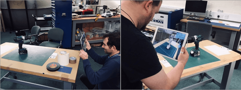
The 3D scanning process was much easier than I envisaged. Firstly I attached the scanner to the back of the lab's iPad Pro. The scanner is an attachment that fits over the camera and has a Thunderbolt connection to feed data to the iPad.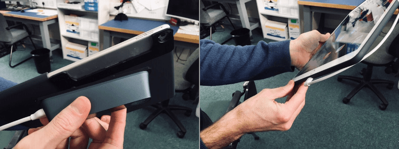
We are using an iPad Pro and the app we used is called 'iSense'. Once you start a scan you get a red 3D bounding box. The item being scanned needs to be completely enclosed by this red bounding cube.
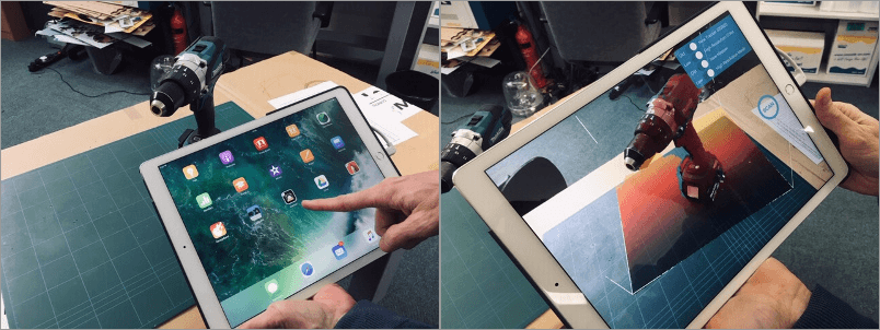
To scan the item we moved slowly around the item and pausing whenever the app requests a 'keyframe'.
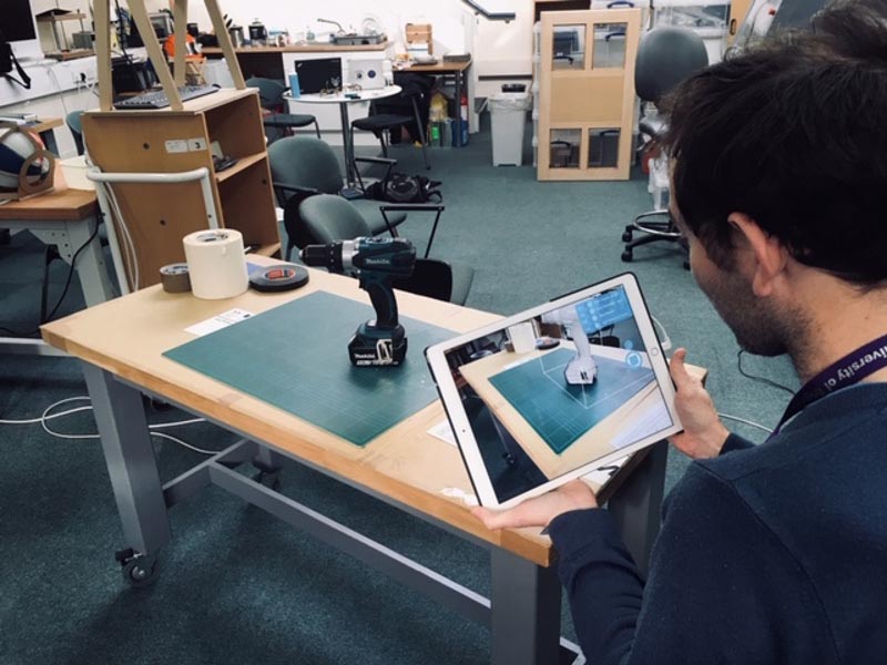
Move the iPad slowly lower and higher to capture details on the lower and upper sides of the item.
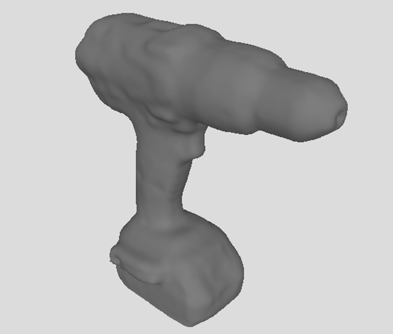
Here is the final model. This is exported as an .obj file.
Meshmixer
Manipulating .obj Files
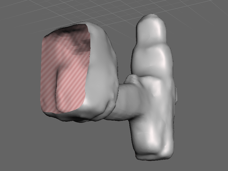
Meshmixer is a free application from Autodesk. I opened my drill scan and rotated it to see the bottom of the scan. Here are the missing parts of the scan that I am going to attempt to repair with Meshmixer.
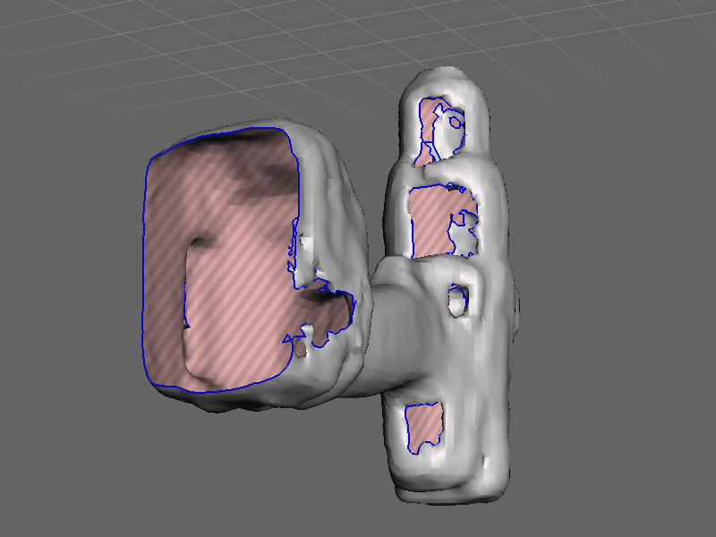
I used a combination of the sculpt brushes in Meshmixer to clean up the scan. I used the 'Unwrap Brush' to remove the fragments inside the drill shell.
Downloads
Right-click and choose 'Save Link As...' or similar to download.
Retro Rocket
Retro Rocket: Fusion 360 Archive (441KB)
Tap Shaped Dimmer Knob
Tap Dimmer Knob: Fusion 360 Archive (517KB)
Tap Dimmer Knob: .STEP (635KB)
Scanned Drill
References
Online
- All3DP (2019) [online] https://all3dp.com/. Available at: https://all3dp.com/2/advantages-and-disadvantages-of-3d-printing/ [Accessed 29 May. 2019].
- Pexels.com: All photos on Pexels are licensed under the Creative Commons Zero (CC0) license.
- The Palaeontogical Association (2019) [online] palass.com. Available at: https://cdn.palass.org/palaeomath_101/moribund/images/shape2/Fig8.jpeg [Accessed 29 May. 2019].