Week 15 - Networking and Communications
This was an interesting week to learn more about different communication protocols. I started this week by learning and summarizing some of the protocols I will use during the Fabacademy. As a scientist, I learned that SPI might be a suitable protocol as it is a synchronous protocol although many wires are required to communicate. Another advantage is that it can uses many slaves. I2C is also an interesting protocol as it requires just a few wires. Serial is also very simple but is asynchronous and cannot use many slaves like the I2C and SPI. In fact, the protocol we will choose to use really depends on our application and the devices we are using.
Serial, I2C or SPI ?
After Neil's lecture on Wednesday and to understand in more depth the different communication protocols, I discussed a lot with Axel the electronic technician in my lab and I followed these tutorials: Serial Communication, I2C, Serial Peripheral Interface (SPI)
USB (universal serial bus), and Ethernet, SPI, I2C, and the serial standard| Parallel VS Serial | Explanation |
|---|---|
| Parallel interface | Multiple bits are transferred at the same time on multiple wires (usually 8 or 16). |
| Serial interface | Bits are transferred one at a time. We can use as little as one wire. |
| Synchronous VS Asynchronous | Explanation |
| Synchronous serial interface | Data signal is paired with a clock signal. All devices share common clock and thus can be synchronize. Synchronous protocols are usually faster but require an important number of wires. |
| Asynchronous serial interface | Data signal is transferred without a clock signal. The good thing is that we can use a minimal number of wires and I/O pins. |
| Serial, I2C and SPI | Explanation |
| Serial Communication | Asynchronous communication between 2 devices. The 2 devices should have their serial protocols configured the same way. Baud rate sets how fast the data are transferred on the line (commonly 9600bps). Data are sent in packets of 5 to 9 bits. Start and stop bits can be used to mark the start and end of a packet. A parity bit can also be added to allow error verification. Serial bus need two wires sending and receiving. On each serial device there is a receiving pin RX and a transmitter TX pin. Serial communication can be (i) Full duplex meaning that data can be received and sent at the same time, (ii) Half duplex, data are received and transmitted on one wire in turn, (iii) simplex data are only transmitted or received on one wire (a LCD screen for example) |
| I2C | Inter-integrated Circuit Protocol. This asynchronous protocol allows multiple slaves. The master chip can communicate with slaves chips using a unique address for each slave. The huge advantage is that it only uses 2 wires but requires devices that can use this protocol. |
| SPI | Serial Peripheral Interface (SPI). It's a synchronous serial data protocol that is used in between a peripheral (slave) and a microcontroller (master) or in between two microcontrollers, one always being the Master. An advantage of this protocol is that it allows fast communication between devices.
This fast and synchronous data protocol makes it a suitable communication protocol for scientific data acquisition. |
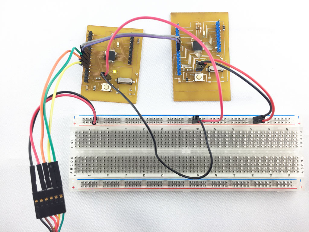
Using the Satshakits
As an anticipation for this weeks assignment, I've made two Satshakit on week13.
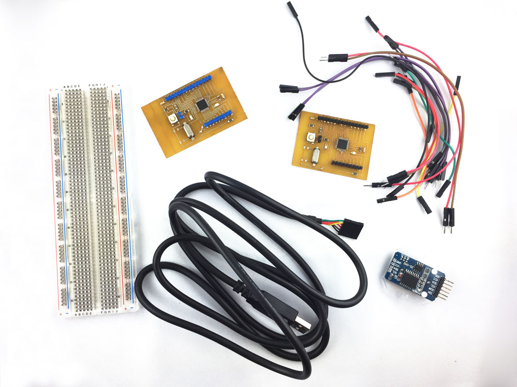
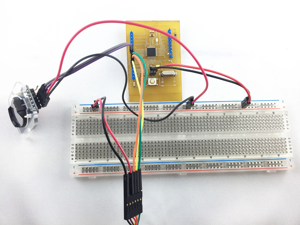
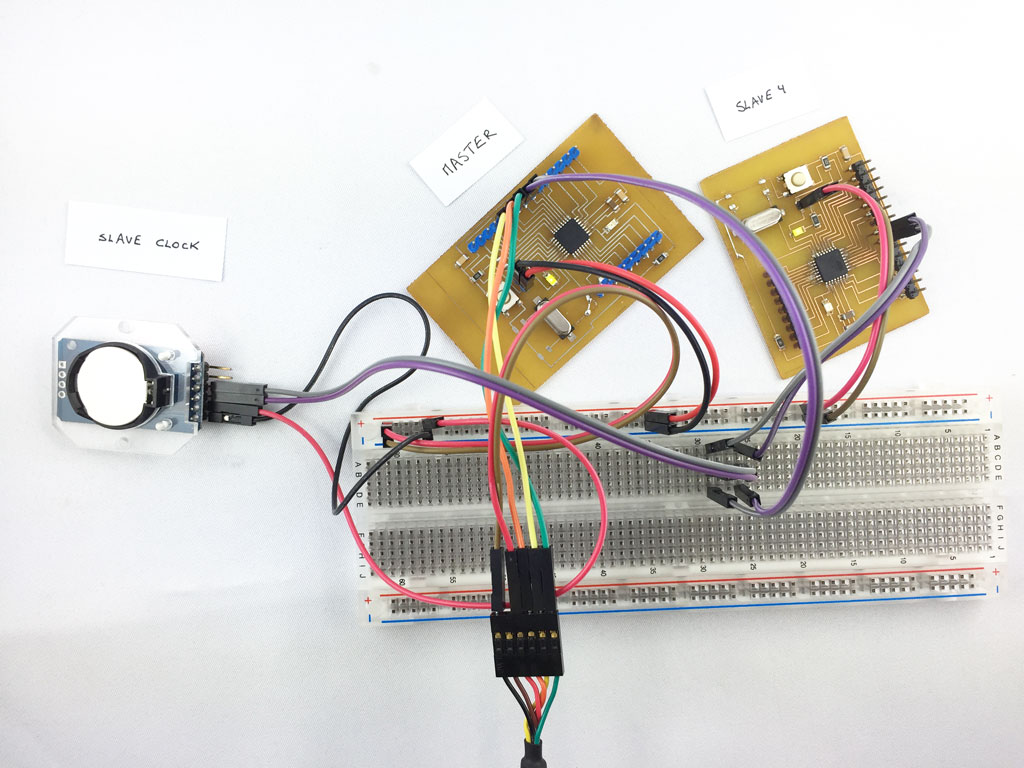
Here is the materials that I used for this assignment: two Satshakits, a FTDI cable, a pin board, a Real Time Clock DS3231, some wires and a laptop.
Master Writer/Slave Receiver
I started by reproducing a simple example that I found on our instructor's Fabacademy page that he himself got inspired from this "Master Writer/Slave Receiver" tutorial for Arduino.
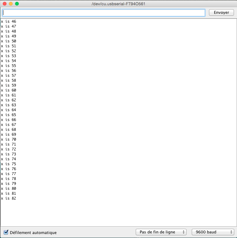
The master board sends a character to the slave. The slave receives this character and print it out on the serial monitor.
Master
      #include

    void setup()
    {
      Wire.begin(); // join i2c bus (address optional for master)
    }

    byte x = 0;

    void loop()
    {
      Wire.beginTransmission(4); // transmit to device #4
      Wire.write("x is ");        // sends five bytes
      Wire.write(x);              // sends one byte
      Wire.endTransmission();    // stop transmitting

      x++;
      delay(500);
    }
Slave
      #include

        void setup()
        {
          Wire.begin(4);                // join i2c bus with address #4
          Wire.onReceive(receiveEvent); // register event
          Serial.begin(9600);           // start serial for output
        }

        void loop()
        {
          delay(100);
        }

        // function that executes whenever data is received from master
        // this function is registered as an event, see setup()
        void receiveEvent(int howMany)
        {
          while (1 < Wire.available()) // loop through all but the last
          {
            char c = Wire.read(); // receive byte as a character
            Serial.print(c);         // print the character
          }
          int x = Wire.read();    // receive byte as an integer
          Serial.println(x);         // print the integer
        }
#include
void setup()
{
Wire.begin(); // join i2c bus (address optional for master)
}
byte x = 0;
void loop()
{
Wire.beginTransmission(4); // transmit to device #4
Wire.write("x is "); // sends five bytes
Wire.write(x); // sends one byte
Wire.endTransmission(); // stop transmitting
x++;
delay(500);
}
#include
void setup()
{
Wire.begin(4); // join i2c bus with address #4
Wire.onReceive(receiveEvent); // register event
Serial.begin(9600); // start serial for output
}
void loop()
{
delay(100);
}
// function that executes whenever data is received from master
// this function is registered as an event, see setup()
void receiveEvent(int howMany)
{
while (1 < Wire.available()) // loop through all but the last
{
char c = Wire.read(); // receive byte as a character
Serial.print(c); // print the character
}
int x = Wire.read(); // receive byte as an integer
Serial.println(x); // print the integer
}
Ok, it's working.
Connecting a clock in i2c
Here I simply use a Satchakit as the master and used the real time clock as a slave.
To make the real time clock to work, I downloaded the following library : DS3232RTC.
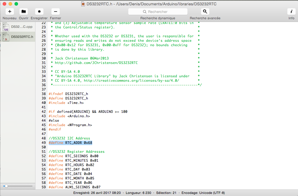
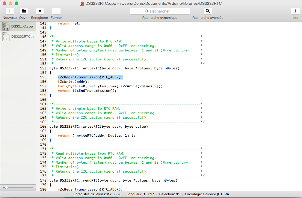
Behind the Arduino libraries
I wanted to learn more what was in the Arduino libraries and not use them as black boxes. I opened the library of the real time clock DS3232RTC and found where was hidden the code that uses I2C to communicate with the clock.
Setting up the clock
To set up the the clock at the right time, I used the SetSerial.ino example that I downloaded along with the RS3232RTC library and use Unix time stamp to set the clock at the right time. See the command and its effect on the 2 images below:
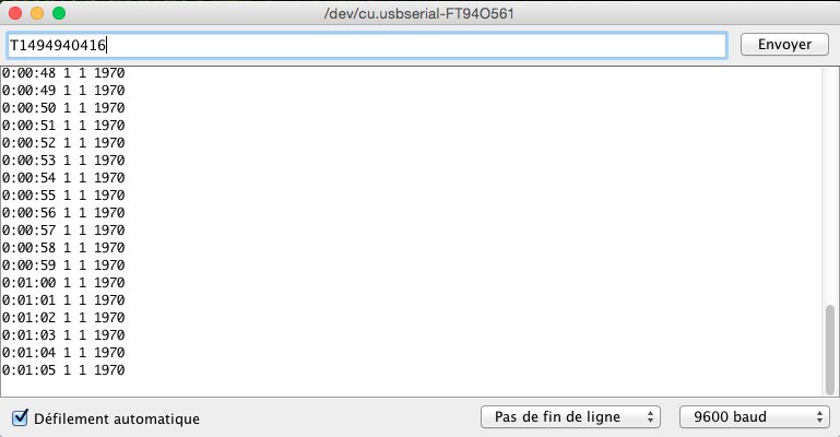
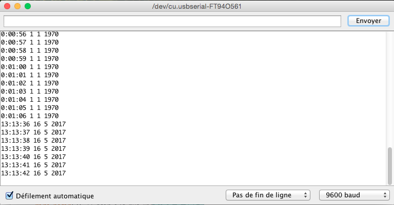
Unfortunately the battery of the clock is low and thus starts back at zero each time we unplug the power from the clock.
Master/Slave clock system
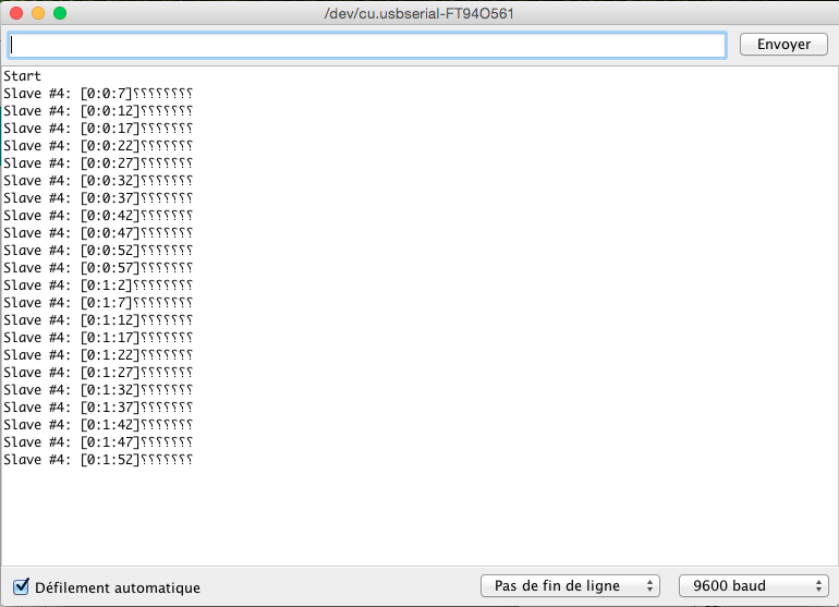
Here I made a simple exercise. The slave #4 on the image below gets the time of the realtime clock (also a slave with a specific I2C address) using I2C protocol. Slave #4 creates a message with the answer from the clock and sends it to the Master which will display it on the serial monitor.
Master
      #include < Wire.h>

          char message[25];

          void setup()
          {
            Wire.begin(); // join i2c bus (address optional for master)
            Serial.begin(9600);           // start serial for output
            Serial.println("Start");
          }

          void loop()
          {

            // Request data from slave #4
            requestValues(4);
            Serial.print("Slave #4: ");
            Serial.println(message);
            delay(5000);

          }

          void requestValues(int slave)
          {
              int i = 0;

              // Request value from slave
              Wire.requestFrom(slave, 15);

              //aquire the value until the register is empty
              while(0 < Wire.available())
              {
                message[i] = Wire.read();
                i++;
              }

              message[i] = '\0';
           }
Slave
      #include < Wire.h>
      #include < DS3232RTC.h>    //http://github.com/JChristensen/DS3232RTC
      #include < TimeLib.h>

      char message[25];

      void setup()
      {
        Wire.begin(4);                // join i2c bus with address #4
        Wire.onRequest(requestEvent);
        setSyncProvider(RTC.get);   // the function to get the time from the RTC
      }

      void loop()
      {
        delay(100);
      }

      void requestEvent()
      {

        int s;
        int m;
        int h;

        s = second(); //get the second value from the RTC
        m = minute(); //get the minute value from the RTC
        h = hour(); //get the hour value from the RTC

        sprintf(message, "[%d:%d:%d]", h, m, s); // this string contains the value of hours, minutes and seconds

        Wire.write(message); // send the message to the master
      }
#include < Wire.h>
char message[25];
void setup()
{
Wire.begin(); // join i2c bus (address optional for master)
Serial.begin(9600); // start serial for output
Serial.println("Start");
}
void loop()
{
// Request data from slave #4
requestValues(4);
Serial.print("Slave #4: ");
Serial.println(message);
delay(5000);
}
void requestValues(int slave)
{
int i = 0;
// Request value from slave
Wire.requestFrom(slave, 15);
//aquire the value until the register is empty
while(0 < Wire.available())
{
message[i] = Wire.read();
i++;
}
message[i] = '\0';
}
#include < Wire.h>
#include < DS3232RTC.h> //http://github.com/JChristensen/DS3232RTC
#include < TimeLib.h>
char message[25];
void setup()
{
Wire.begin(4); // join i2c bus with address #4
Wire.onRequest(requestEvent);
setSyncProvider(RTC.get); // the function to get the time from the RTC
}
void loop()
{
delay(100);
}
void requestEvent()
{
int s;
int m;
int h;
s = second(); //get the second value from the RTC
m = minute(); //get the minute value from the RTC
h = hour(); //get the hour value from the RTC
sprintf(message, "[%d:%d:%d]", h, m, s); // this string contains the value of hours, minutes and seconds
Wire.write(message); // send the message to the master
}
Ok, it's working.
As the battery of the clock is low, the clock always starts back to 0 when we plug back power (after unpluging).
The inverse question marks below are due to the length of the message that is longer than what is necessary to print the time.