Final project
The kit modules fabrication
For my final project, I decided to create different modules:
- a stepper motor driver module
- a power supply module
- a camera linked to a Raspberry Pi module
- different mechanical components for the kit
The stepper motor driver module
Overview
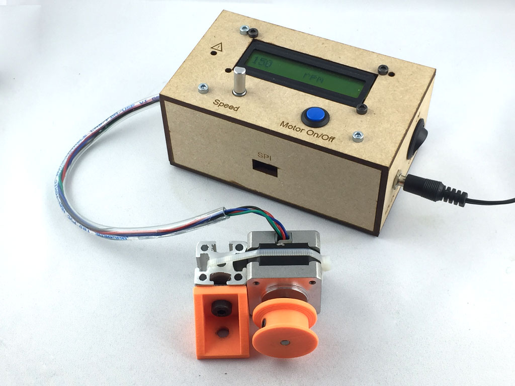
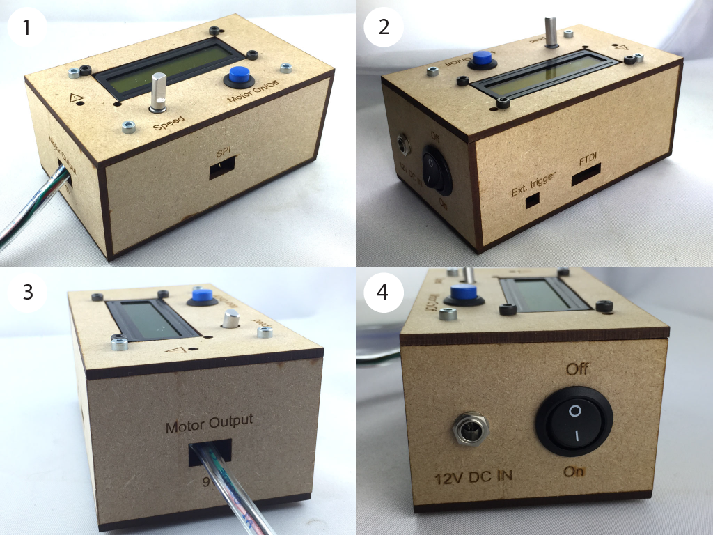
This module allows to control 10V stepper motors in speed and direction. For physics experiment, pros are when we want control of the speed and the rotation angle and cons are that torque is low and rotation speed is quite limited (here 175rpm). This module is standalone but can also be wired and controlled remotely from a central unit (a Raspberry Pi for instance). In the box there are a microcontroller ATMega328 and a Dual H drive motor driver DRV8833, a 5V and 9V current regulators. The module is powered up in 12V DC IN and regulates current in 5V to power up the microcontroller and 9V to power up the stepper motor. There is a power button on the side, a motor on/off button, a possibility to wire an external trigger, and a rotating button to control the motor rotating speed which is displayed on a LCD screen. The module is programmable using a FTDI cable and can be remotely controlled using Serial communication or SPI communication protocols.
Electronic design
Here, I'll explain all about the electronic design of the stepper motor module.
I wanted to make a module that is simple to use and allows lots of control possibilities. The module allows to control, in speed and direction, a stepper motor of 10V using a microcontroller and a dual H-bridge motor driver.
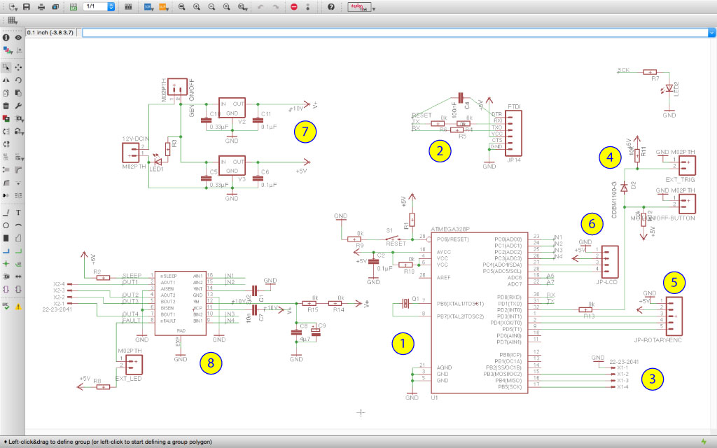
The electonic board is made of (the corresponding parts are annotated on the eagle schematic here below) :
- a microncontroller ATMega328P that is programmed to run the module (the design is based on the Satchakit made on week 13);
- a FTDI connection;
- a SPI connection;
- a motor on/off button and a possibility to connect an external trigger;
- 5 header pins to connect a rotary encoder (to control the motor rotation speed);
- 4 header pins to connect a LCD screen with an I2C communication protocol (to indicate the motor speed);
- 2 current regulators. The board is powered in 12V DC IN which is converted in a 9V DC current to run the stepper motors and a 5V DC current to power up the board;
- a dual H-bridge motor driver - DRV8833 (see week 10 for more information on the driver).
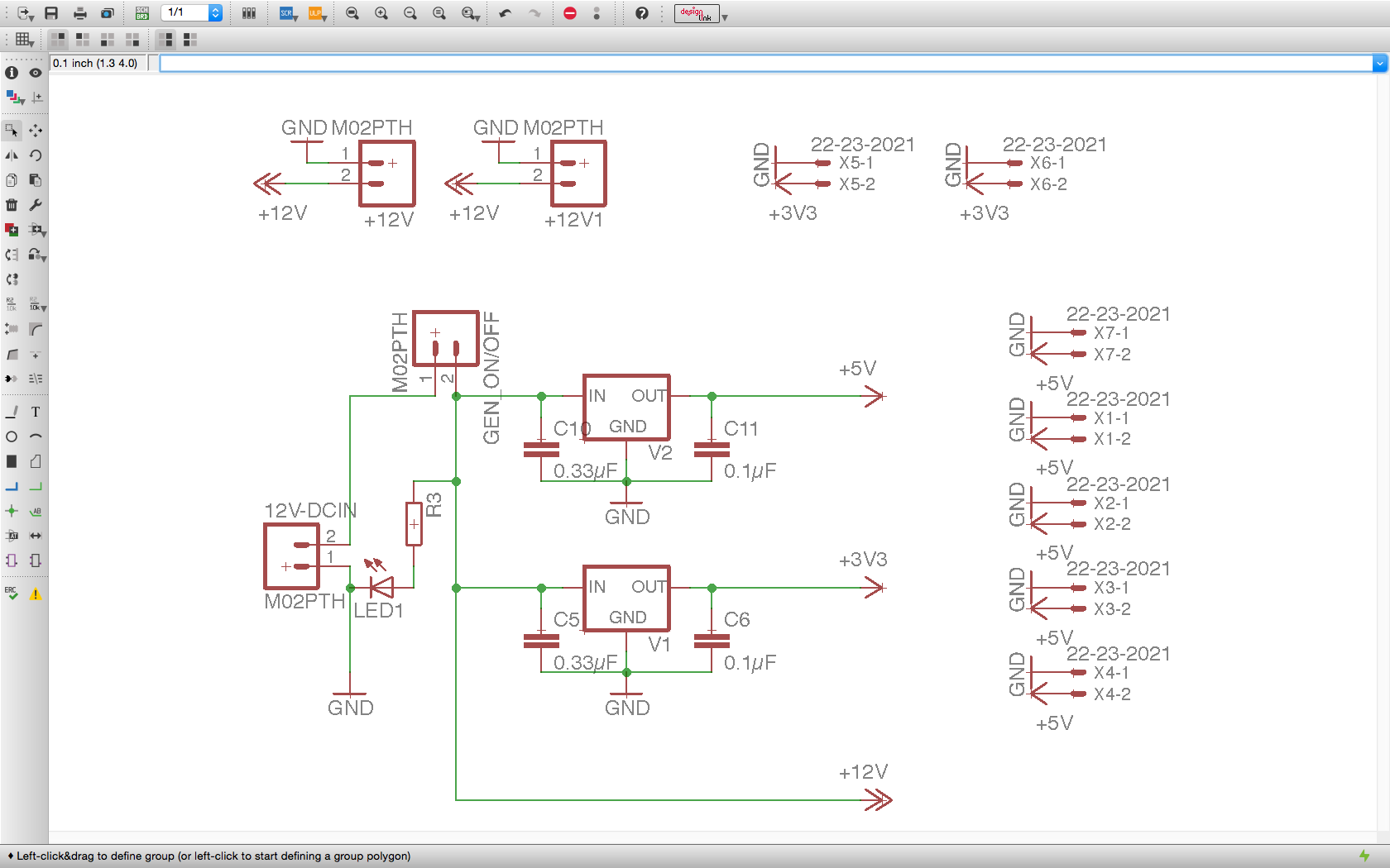
Here is the schematic that I made in Eagle.
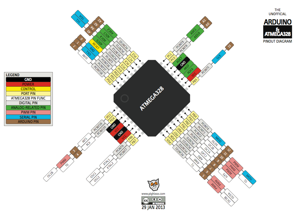
To build the electronic schematic I used the following pinout diagram that summarizes the pin functions of the ATmega328.
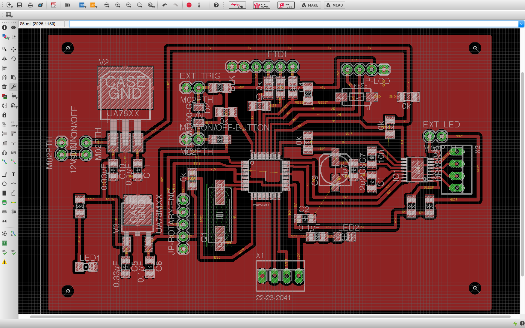
I then designed the board in Eagle from the schematic above. That was not an easy part as there are a lot of components.
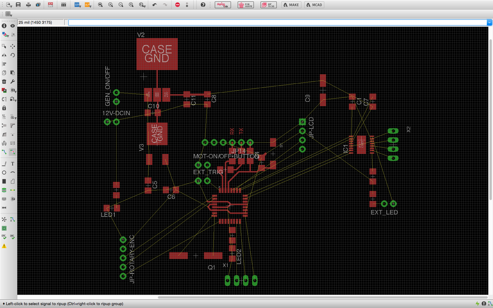
Here is the final board ready to be produced.
Electronic board fabrication
I decided to use chemical etching to produce the board (as explained on week 4) as it is very high resolution and we have a waste facility to dispose of the chemicals in our university.
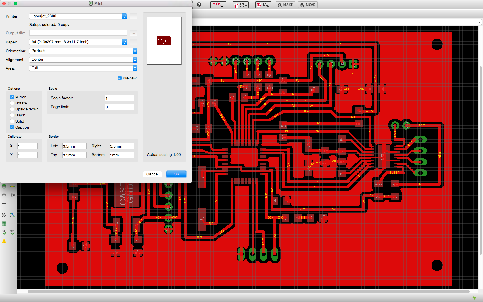
First, I printed the mask on a transparent sheet using a laser printer. I used the high resolution setting and the mirror option.
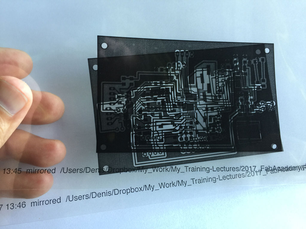
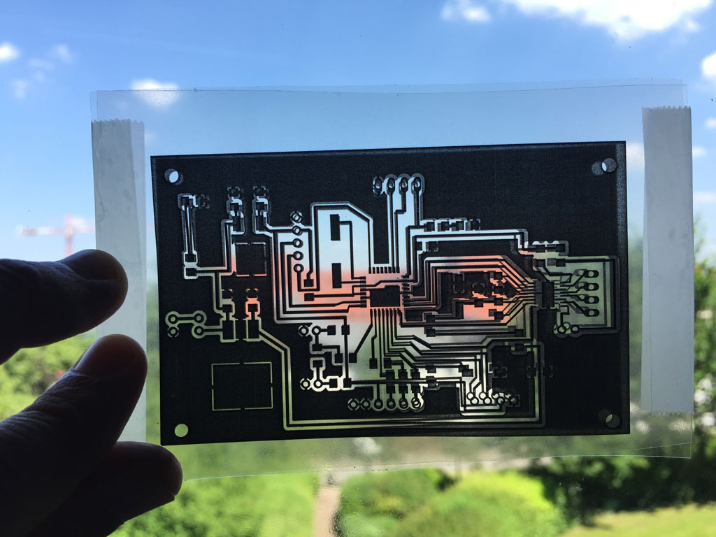
To make a good mask (that block UV where it is dark), I printed and aligned two masks.
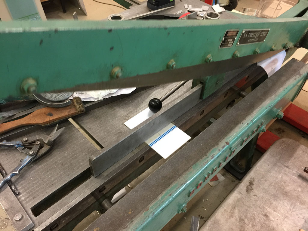
We cut the PCBs at a suitable size.
We then layed down the mask on the UV lamp.
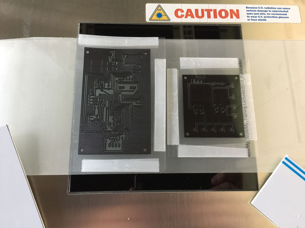
and place the PCB with the photosensitive resin on top of the mask. We switched on the UV light and waited for 12 minutes.
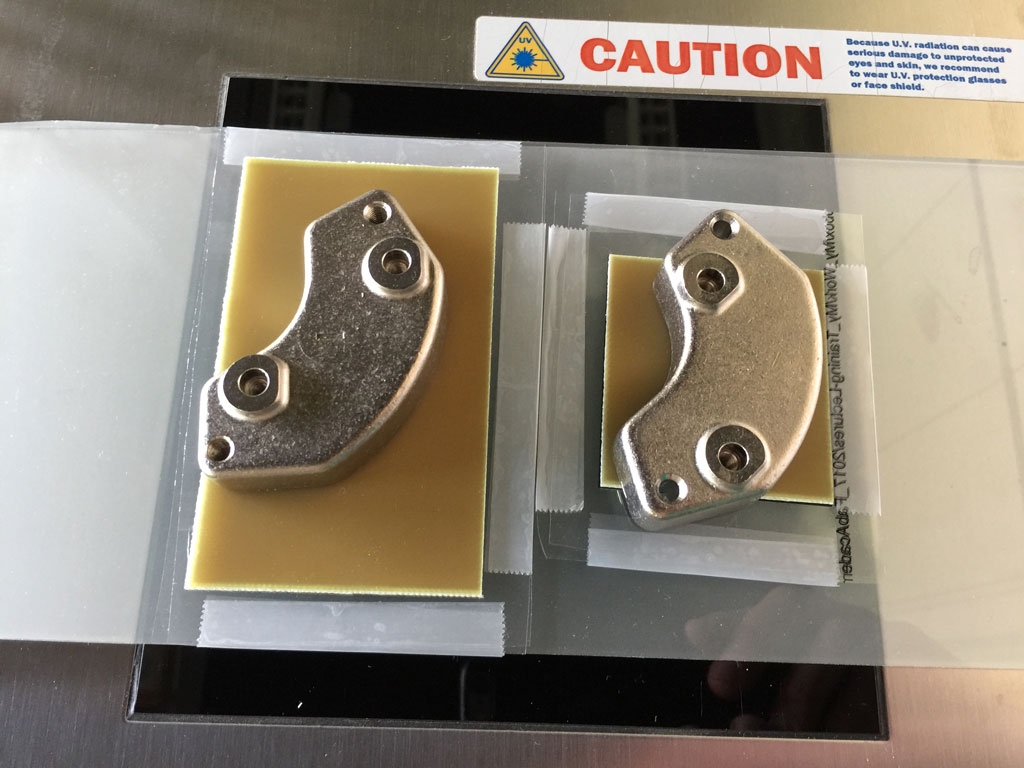
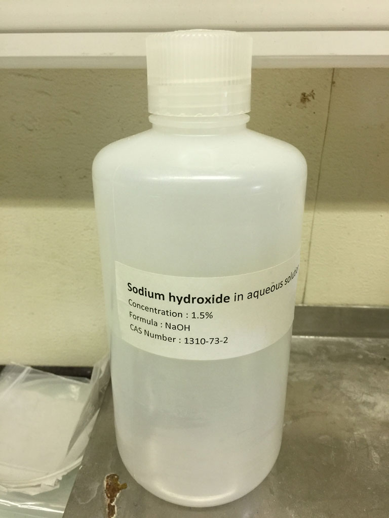
We removed the uncured resin with a little bit of Sodium hydroxide.
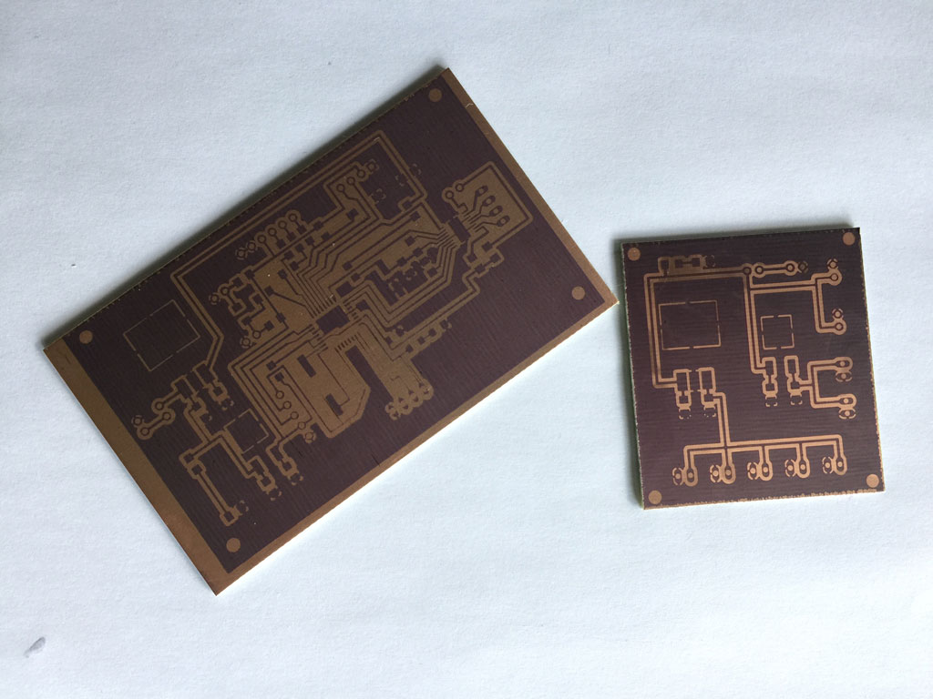
The PCBs are ready to be etch. the left on is for the motor driver module and the right one is for a power supply that I made.
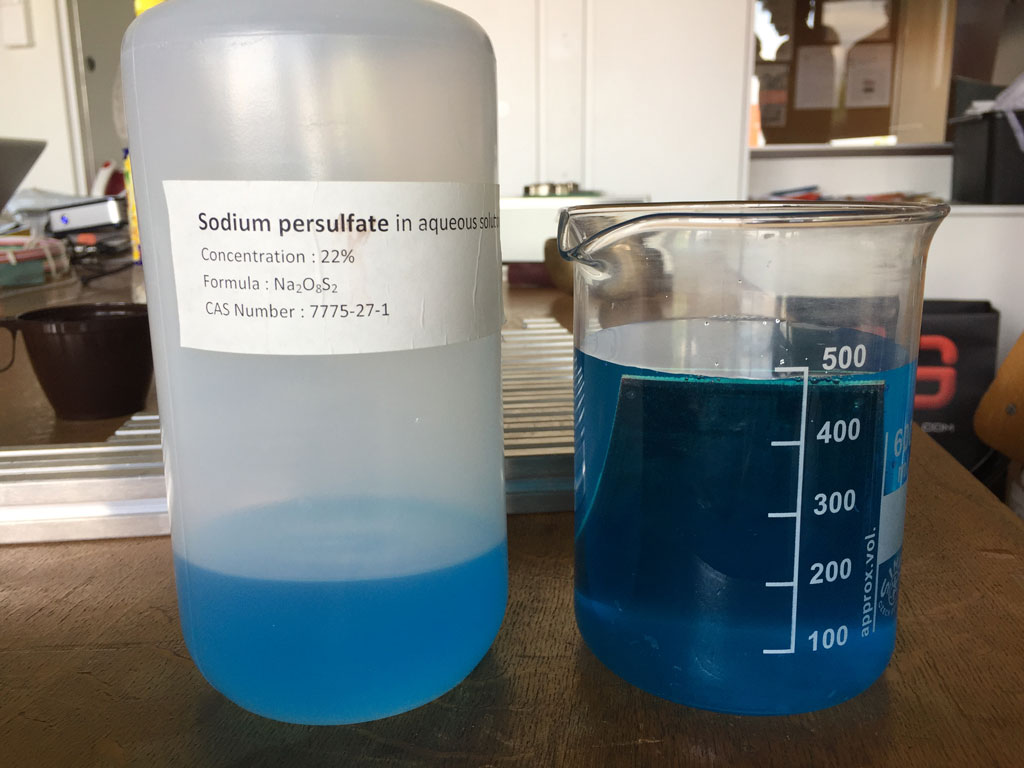
We plunged the PCBs into a Sodium Persulfate solution and heat the whole at 100°C and waited for a few tenth of minutes. We have to regularly check if the copper is etched. If we wait for too long, the protected copper by the resin might start to etch also, and some copper tracks might disapear.
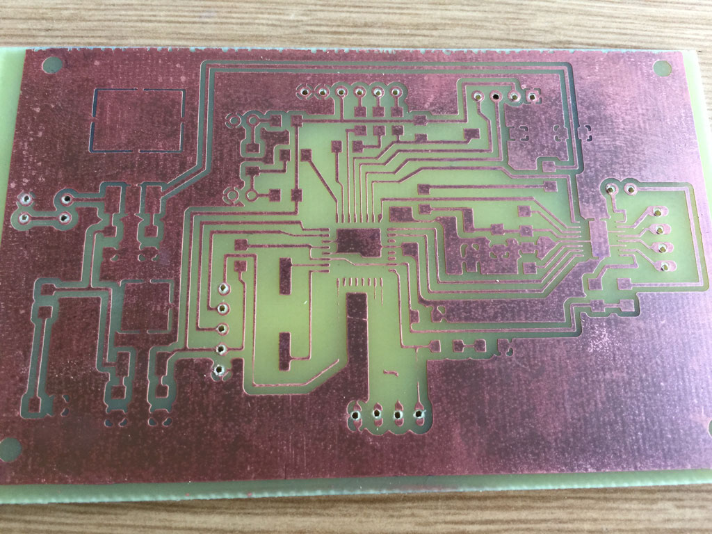
Indeed, a few tracks disappeared. We will have to mend those later.
As the microcontroller and the driver are really small, I chose to solder the components using soldering paste. Be aware there are one or two mistakes on the board that we have spotted during the checking and fixing phase after everything was soldered. For example the large condensator is in the wrong position and the led in the right down position is also wrongly positioned. The resistance on the far left has also been changed.
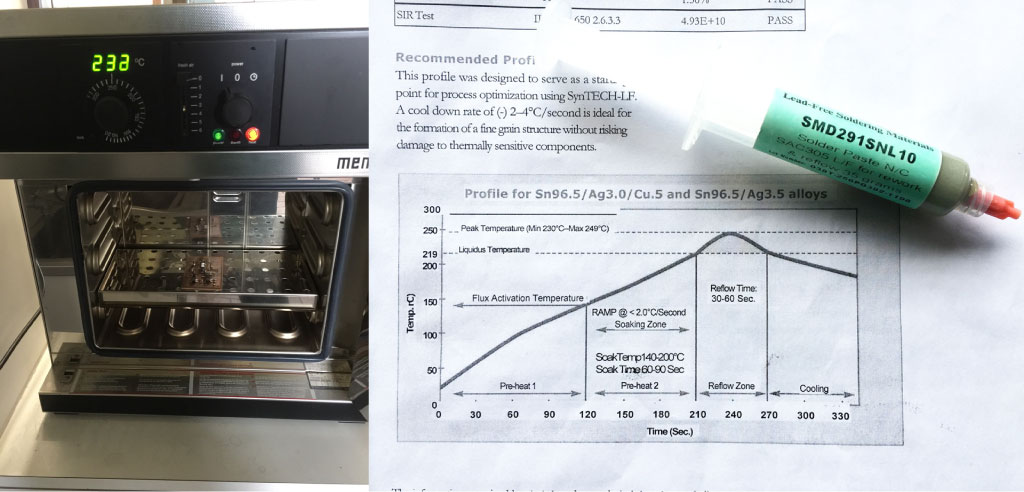
Then I put the board in the oven that was preheated at 150°C. I then set the temperature of the oven to 250°C and let the oven increase in temperature with the board inside. Once the temperature reached 220°C, I waited for 1 minute before stopping the oven and letting the board to decrease in temperature. This ramping method for soldering using this soldering paste was given in the datasheet of the paste (see the curve below).
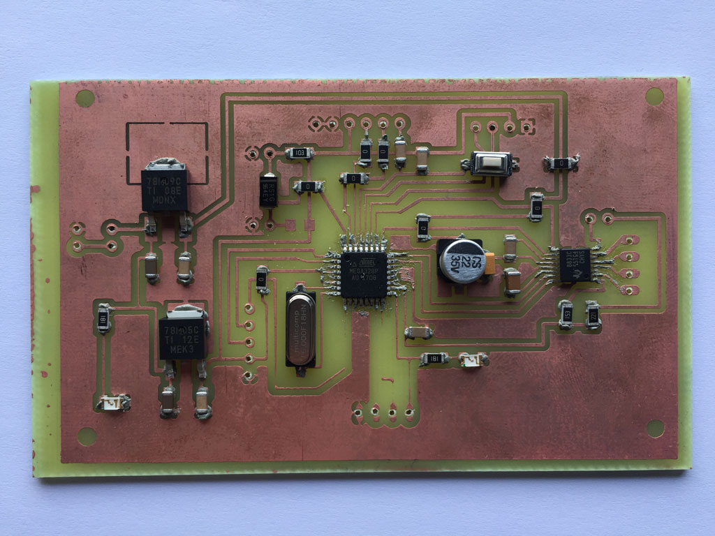
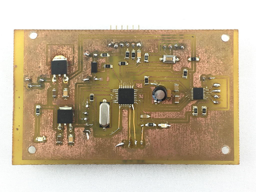
Here is the board out of the oven with some changes of led, capacitor and resistances that were required to make the board working. We can see some level of oxidation which seems inevitable with this soldering method.
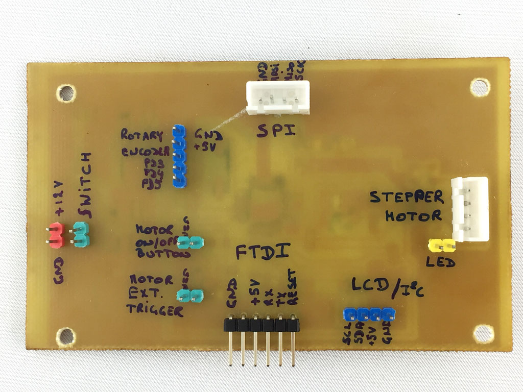
Here is the other side of the board ready to be connected to the different components.
Making my own wires connectors, wire sleeve and wire-to-board connector system
Axel from my lab showed me how to make my own wires and connectors.
Wire sleeves
I also used a piece of PVC pipe to make a sleeve for the wires of the stepper motor driver.
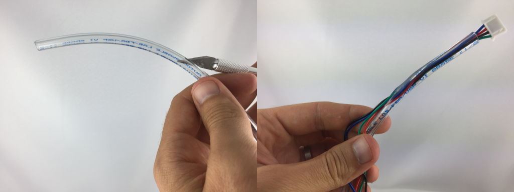
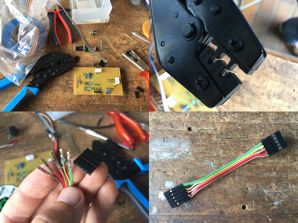
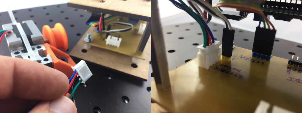
Wire-to-board connector system
I used Molex keyed connectors to allow the stepper motor to be connected and unconnected easily without inverting the wires.
Making a first case
I then made a first case and assembled the LCD screen, the buttons, the rotary encoder, the motor fault led, and the DC IN connector.
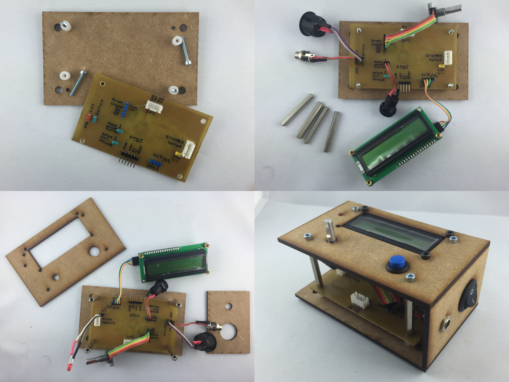
Making a second case
Spiral management. I made a second case that is easy to assemble and disassemble with opening for the connections.
Programming the module
Uploading a bootloader
To program the microcontroller easily using a FTDI cable and the Arduino IDE, I uploaded a bootloader on the microcontroller following the steps described in week 13
Uploading the module program
To see the module running on a video jump to the last version of the segregation experiment section
  /*
  modified by Denis Terwagne on the 17/06/2017
  inspired by the work of Danny van den Brande on the KY-040 Rotary encoder
  http://www.instructables.com/id/Arduino-Rotary-Encoder-Simple-Example-KY-040/
   */

  #define button 2

  #include
  LiquidCrystal_I2C lcd(0x27, 2, 1, 0, 4, 5, 6, 7, 3, POSITIVE);
  #include


   int CLK = 5;  // Pin 9 to clk on encoder
   int DT = 4;  // Pin 8 to DT on encoder
   int SW = 3;

  //STEPPER MOTOR
  const int stepsPerRevolution = 400;  // change this to fit the number of steps per revolution
  // for your motor
  int stepperSpeed = 150;
  // initialize the stepper library on pins 8 through 11:
  Stepper myStepper(stepsPerRevolution, A0, A1, A2, A3);

   int RotPosition = 0;
   int rotation;
   int value;
   boolean LeftRight;

   void setup() {
     // initialize the serial port:
     Serial.begin (9600);

     //setup the rotary encoder pins
     pinMode (CLK,INPUT);
     pinMode (DT,INPUT);

     rotation = digitalRead(CLK);

    // set the speed at "stepperSpeed value" rpm:
    myStepper.setSpeed(stepperSpeed);

    // The LCD is 16x1 but should be programmed as a 8x2
    // set up the LCD's number of columns and rows:
    lcd.begin(8, 2);
    // set the cursor to column 0, line 1 (the second line corresponds to the second half of the 16x1 lcd)
    lcd.setCursor(0, 1);
    lcd.print("rpm");
   }
   void loop() {
     value = digitalRead(CLK);
       if (value != rotation){ // we use the DT pin to find out which way we turning.
       if (digitalRead(DT) != value) {  // Clockwise
         RotPosition ++;
         stepperSpeed = stepperSpeed + 5;
         LeftRight = true;
       } else { //Counterclockwise
         LeftRight = false;
         RotPosition--;
         stepperSpeed = stepperSpeed - 5;
       }
       if (LeftRight){ // turning right.
         Serial.println ("clockwise");

       }else{        // turning left.
         Serial.println("counterclockwise");

       }
       Serial.print("Encoder RotPosition: ");
       Serial.println(RotPosition);
       // this will print in the serial monitor.
       Serial.print("stepperSpeed: ");
       Serial.println(stepperSpeed);

     }
     rotation = value;

     // set the cursor to column 0, line 0
      // (note: line 1 is the second row, since counting begins with 0):
    lcd.setCursor(0, 0);
    lcd.print(stepperSpeed);

     if (digitalRead(button) != true){
      if (stepperSpeed >= 0) {
     myStepper.step(stepsPerRevolution/100);
     // set the speed at "stepperSpeed value" rpm:
    myStepper.setSpeed(stepperSpeed);
      }
      if (stepperSpeed < 0) {
     myStepper.step(-stepsPerRevolution/100);
     // set the speed at "stepperSpeed value" rpm:
      myStepper.setSpeed(-stepperSpeed);
      }
     }
   }
The code can be and will be improved allowing the motor to rotate in the opposite direction and setting a maximal speed value for the stepper motor. Over 175rpm the motor does not work properly.
The power supply module
To power up the different modules of the kit, I envisioned making a power supply module to deliver 3.3V, 5V and 12V. I have designed it in Eagle but haven't finished its fabrication.
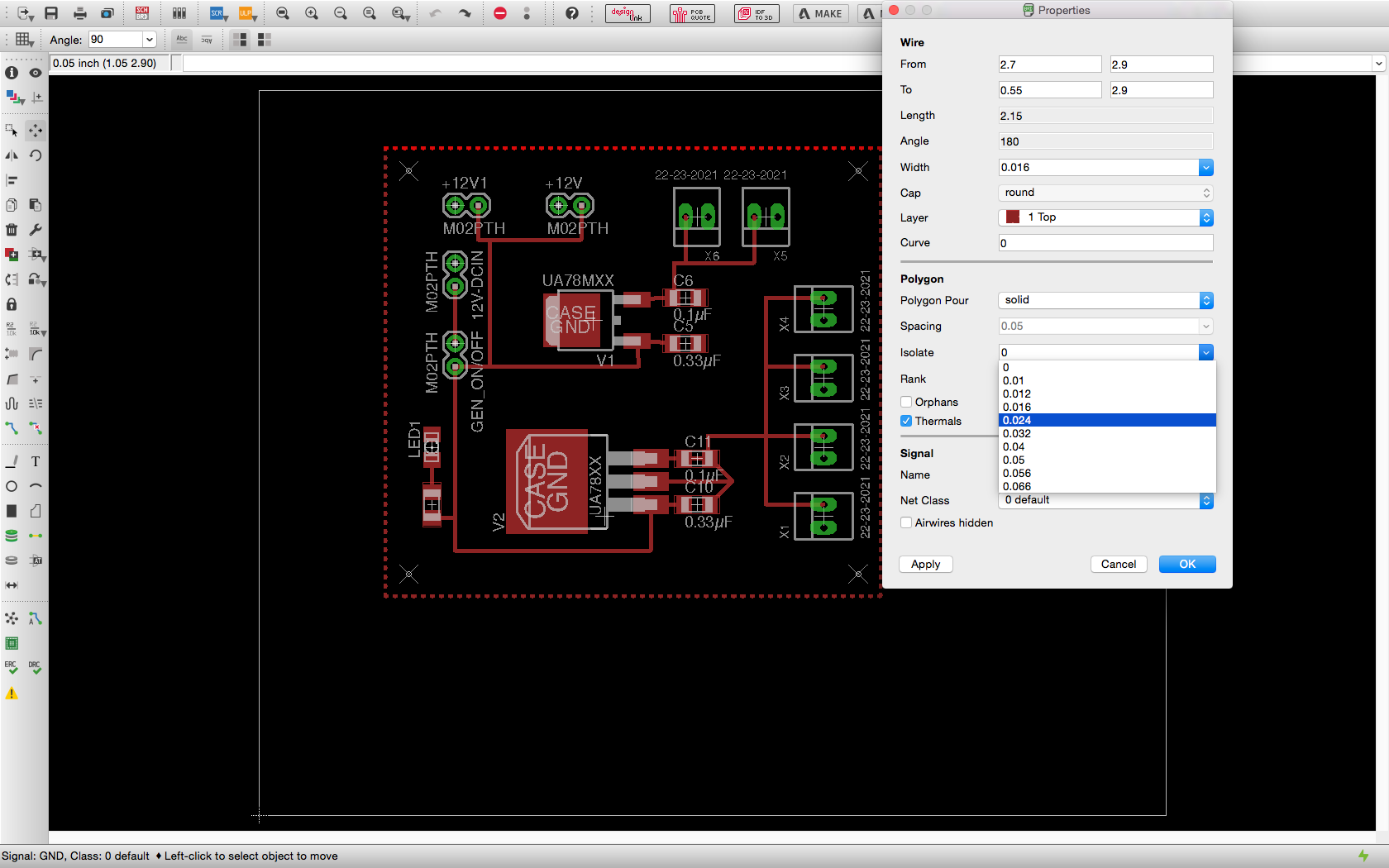
After having made the schematic, I designed the board. In the panel below, I'm specifying the isolation to be 0.024 which separates the wires to the polygon GND.
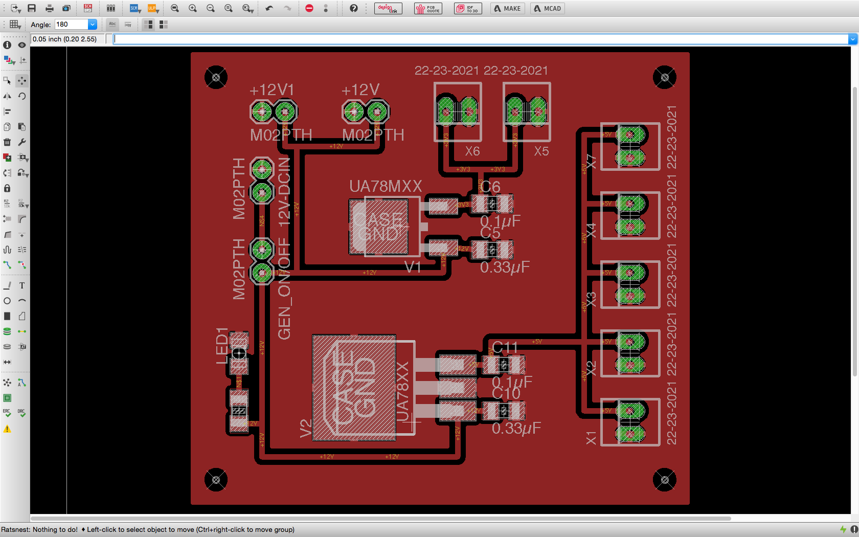
Here is the final board to print and produce
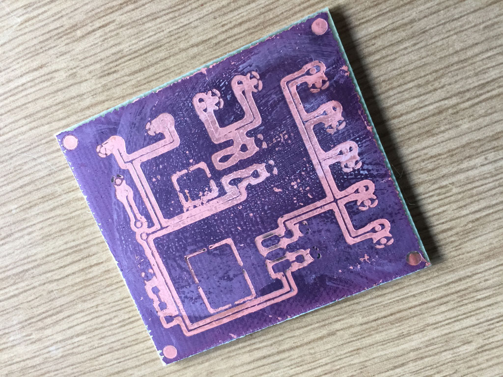
Unfortunately the etching did not work properly. I will have to fabricate it again later (after the Fabacademy evaluation).
The camera module
For more information, please explore the assignment on week 16 - Interface and application programming.
This module consists of a Pi camera controlled from the central module, a Raspberry Pi, which allows to process and analyze images in live using python and openCV scripts.
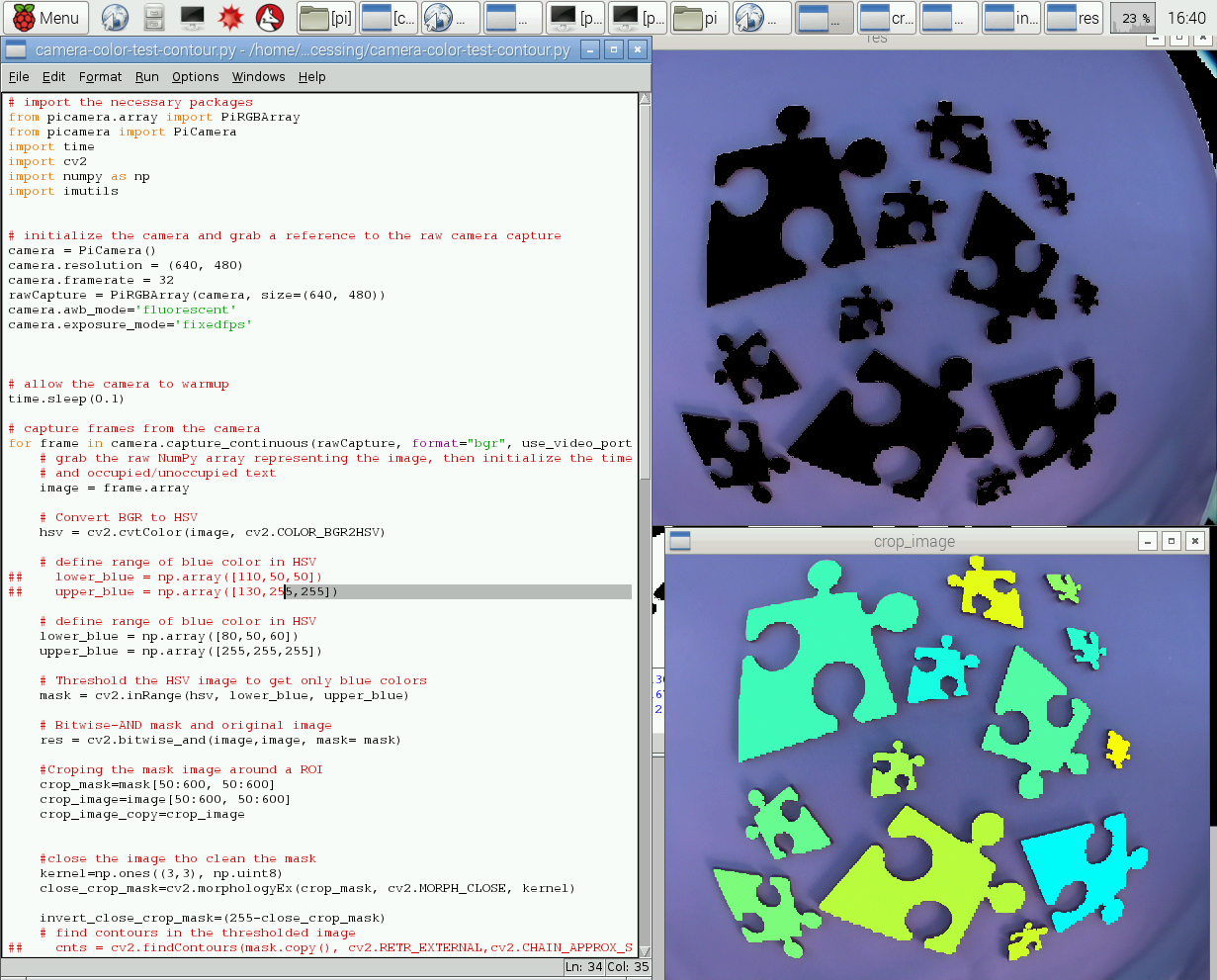
For the physics experiments on granular media that I developed here, we can think of measuring the size and compaction of the grains, recognizing or characterizing the shape of the grains... so many things to measure and get information on in real time. On week 16, I made a python script that measures in real time the area of puzzle pieces that are in the camera field of view and displays a colored image, each colors corresponding to a piece size.
Why real time ? The idea is to develop a camera interface that gives real time information on the running experiments. The dream is to perform experiments in augmented reality so the operator can interact with its experiment and instantly see the results of the parameter he changes.
This module was mainly developed during week 16. It will require to redesign some elements and think of a better integration. It is something I'll continue after the Fabacademy evaluation.
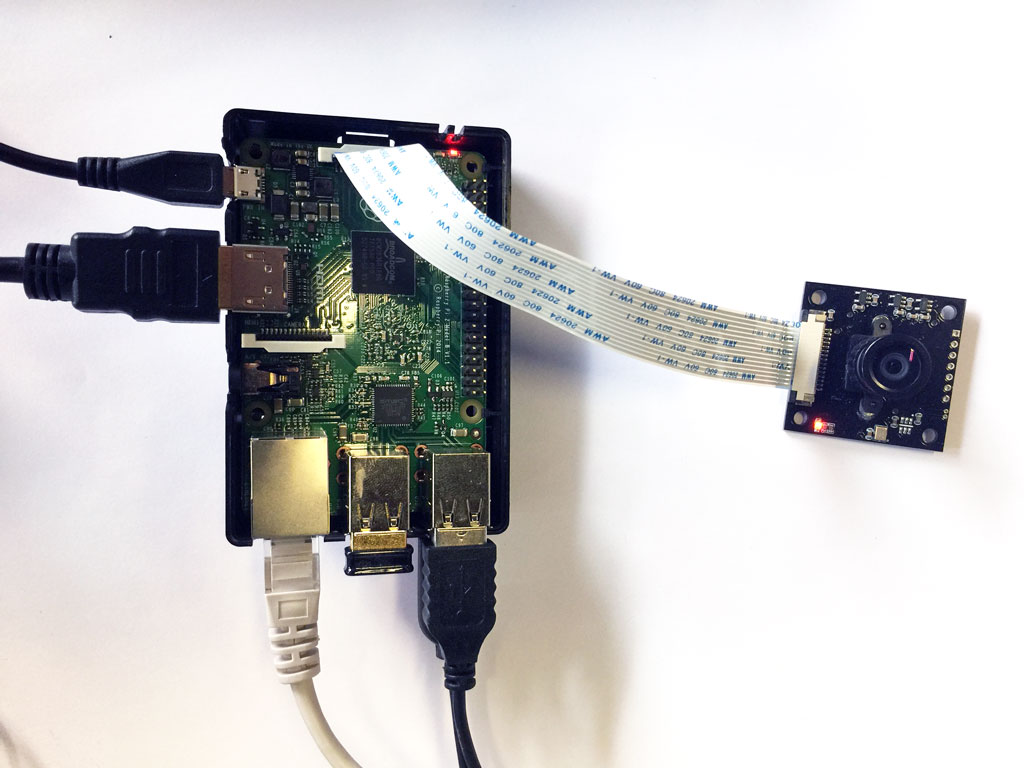
A raspberry Pi and a Pi camera.
The module consists of a pi camera and a Raspberry Pi model 2. As a language to interface it, I chose Python along with the openCV library and the Picamera.camera module.
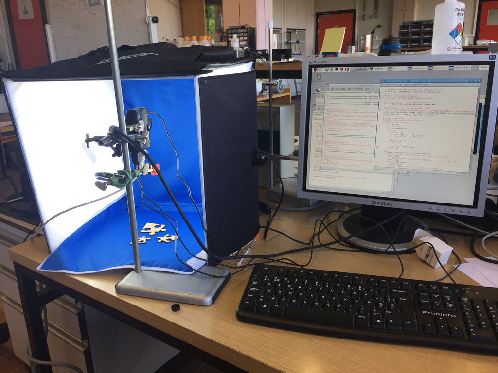
To ease the real time image analysis, I used a light tent. The pi camera and the raspberry are connected to a screen, a keyboard and a mouse.
Real time recognition of (puzzle) pieces sizes
Here is a screen shot of the running python code on the Raspberry PI
Here is a video showing the live recognition of piece sizes.
Virtual Network Computing - VNC
If we want to access the Raspberry Pi from our computer or ipad, we can set up VNC on the Raspberry Pi. To access it from the mac or the ipad, I followed this protocol which worked successfully.
Mechanical components
The kit is meant to be assembled and disassembled. Everything holds in a suitcase.
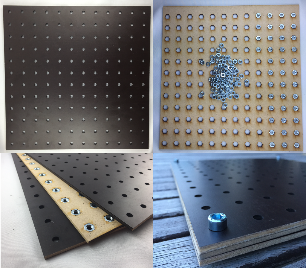
Breadboard
Inspired by the optomechanical scientific tools and the lego bricks, I made a breadboard on which we can assemble and fix the elements of the kit with 6mm bolts. The breadboard is made of 3 flat pieces of wood 30x30cm the central one in MDF 3mm and the two others also in MDF 3mm but recovered with a coating of bakelite. Holes with 6mm bolts are displayed all over the board and are spaced on a horizontal grid, each holes being separated by 2.5cm. The three wood pieces have been cut with a laser cutter and 144 nuts have been placed in the spacing provided in the central wood piece. To avoid the nuts to move, I took into account the laser kerf in my design so the nuts fit perfectly in the holes.
Making the wheels
For the experiment on the grain segregation in a rotating tube, I needed wheels on a rotating axis that make the tube to rotate by friction. So I imagined a technique to glue a black foam with a high friction coefficient on a cylinder. Here below is the first version of the wheels. I then made the wheels in acrylic using the laser cutter which allows are more precision than the wooden one that I made using a drill and a hole saw.
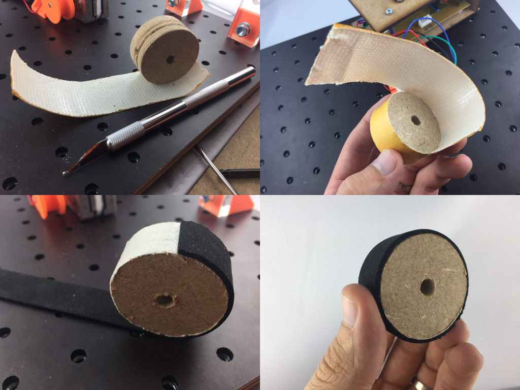
As a next step, I would like to mold the rubber part in urethane (a technique we learned on week 12 - molding and castings).
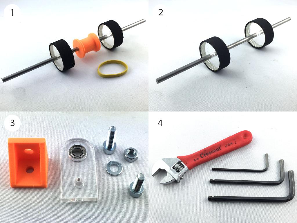
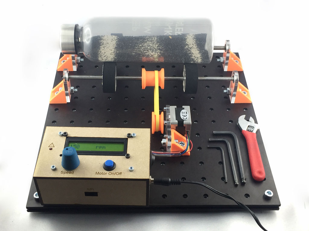
Rotating axis and kit tools
(1-2) For the rotating axis I used metallic bars, a spool that I designed and 3D printed, a rubber band, laser cut acrylic wheels. (3) The laser cut axis holder were made using 5mm acrylic and a laser cutter, with press-fit ball bearings, a 3D printed right-angle bracket that Axel Cornu designed and gave me the permission to use, M6 bolts and nuts. (4) The tools to assemble the kit are limited to a mini adjustable spanner and a small set of hex keys.
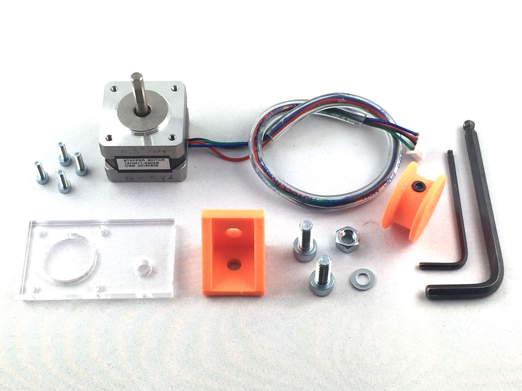
Stepper motor components
The stepper motor is easy to assemble and fix on the breadboard. It is made of a 10V stepper motor with a molex connector and a pvc tube sleeve for the wires, a 3D printed right angle bracket and a 2D acrylic piece to fix the motor to the right-angle bracket, a 3D printed spool to fix on the motor shaft and a few bolts and nuts to fix the whole on the breadboard.
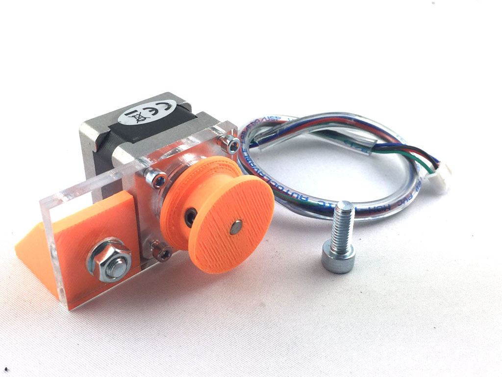
Here is the stepper motor assembled and ready to be fixed on the breadboard.
Building physics experiments
Here is the grain segregation in a rotating tube experiment that is assembled with most of the modules and components presented above.
Future modules
The kit will continue to evolve and I'm thinking of implementing new modules to create more experiments. Phase transition in grains, can be shown using sand, a latex hand glove, tubes and a vacuum pump modules. With Axel Cornu in my lab, we quickly assembled the following experiment that Neil affectionates a lot. The latex hand glove is full of sand and air is pumped using a small vacuum pump that can decrease the pressure up to -0.7atm. The atmospheric pressure around the glove compress the sand increasing the friction in between grains. When vacuum is done, the glove feels like a solid, when the pump is set off, the glove is soft and sand act like a liquid. That's a great way to show phase transition in granular media.