Final Project - Electronics
DC Motor Board - Version 01 solo output
I started from the board that I made during Week 10 - Output Devices which was able to turn a DC motor.
Testing the power of the DC motor
I checked if the motor was capable to turn a impeller similar to that I was designing.
Here without the impeller, the speed is high.
Here the motor can still turn the impeller but the speed looks quite low. It will probably not scution the air through the filter properly and I should think to a stronger DC motor.
Here I am testing the speed of the impeller made in playwood 4 mm. The motor can still manage this work pretty well.
DC Motor Board - Version 02 input, output and serial comunication
I also worked on a new board that was capable to manage some inputs from three buttons to change the speed of the impeller of the filter.
I figured out that for my application an h-bridge was not necessary, because I didn't need to reverse the rotation of the motor, and a transistor was sufficient.
I looked for some examples with transistors and I found one on the Arduino Starter Kit that I have already made in the past and one in the book Make: AVR Programming that I found interesting for my final project.
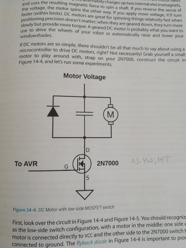
From Make: AVR Programming - DC Motor example
In the diagram one flyback diode provides a path for the current that's flowing through the motor to continue on after we've switched the motor off.
The capacitor smooths out noise that the DC motor itself makes as the brushes inside switch from one polarity to the other.
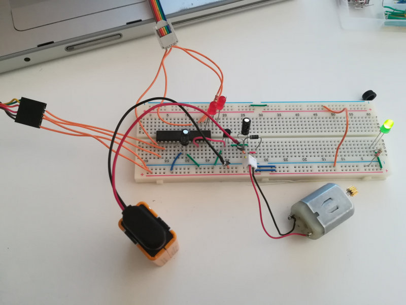
The layout with the wires and the components:

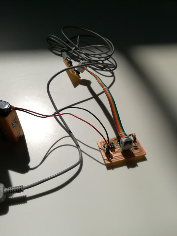
Here my breadboard with the connections to the FabIsp to program the AVR ATMega, and the connections to the FTDI cable for power, ground and serial comunication.
Here below the whole C code:
         /* Demos PWM control of a DC motor */

// ------- Preamble -------- //
#include
#include
#include
#include "pinDefines.h"
#include "USART.h"

#define SPEED_STEP_DELAY 2                             /* milliseconds */

// -------- Functions --------- //
static inline void initTimer0(void) {
  TCCR0A |= (1 << WGM00);                             /* Fast PWM mode */
  TCCR0A |= (1 << WGM01);                       /* Fast PWM mode, pt.2 */
  TCCR0A |= (1 << COM0B1);                        /* output PWM to pin */
  TCCR0B |= (1 << CS02);                 /* Clock with /1024 prescaler */
  //TCCR0B |= (1 << CS00);         /* Clock with /1024 prescaler, pt.2 */
}


int main(void) {

  uint8_t updateSpeed;

  // -------- Inits --------- //
  initTimer0();
  OCR0B = 0;

  ANTENNA_DDR |= (1 << ANTENNA);    /* now hooked up to MOSFET, output */
  LED_DDR |= (1 << LED0);
  LED_DDR |= (1 << LED1);

  initUSART();
	printString("DC Motor Workout\r\n");

  // ------ Event loop ------ //
  while (1) {

    updateSpeed = getNumber();

                                      /* Ramp up/down to desired speed */
    if (OCR0B < updateSpeed) {
      LED_PORT |= (1 << LED0);
      while (OCR0B < updateSpeed) {
        OCR0B++;
        _delay_ms(SPEED_STEP_DELAY);
      }
    }
    else {
      LED_PORT |= (1 << LED1);
      while (OCR0B > updateSpeed) {
        OCR0B--;
        _delay_ms(SPEED_STEP_DELAY);
      }
    }
    LED_PORT = 0;                                           /* all off */

  }                                                  /* End event loop */
  return 0;                            /* This line is never reached */
I typed to check connections
avrdude -p m168 -c usbtiny
I flashed the AVR simply with (please see for more explanations my Exercise 08):
make flash
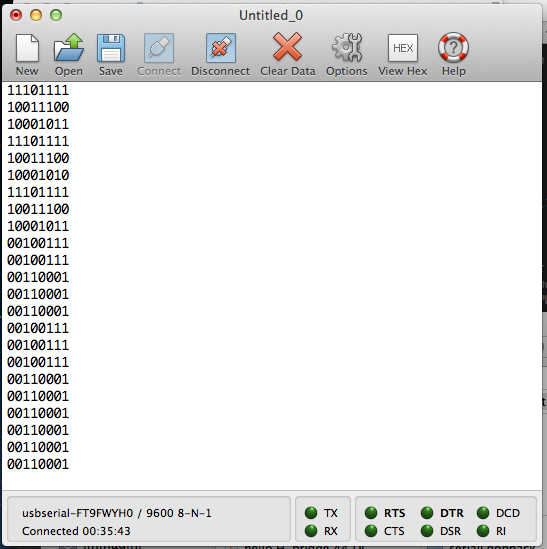
I opened Coolterm to start the serial connection with the AVR microcontroller. In the C code the function getNumber() takes in a number (as ASCII characters) from the serial line and trasforms it in speed of the motor.
I typed some characters and I got answers in the terminal but the motor didn't turn properly.
Here below the answers when I typed the values to turn the motor at different speeds.
DC motor board with input and output
I started working to the new board of my design with three bottons that will mange different speeds of the DC motor.
I started looking for a transistor N-channel sourface mounted for my board: I found one in the Fab Academy's inventory, so I asked to Enrico Bassi to order it.
I looked the data sheet in order to know the pinout layout and the limiting values of voltage and current.
The voltage I will use to turn the motor will be 9V which is fine because the limiting value is 60V. I will have maximum 5V between the gate and the source, which is far below the limit of +/-20V.
About current I read from the data sheet that the limit value is 350mA at the drain.
So I tested the drain current using a tester and the value was 90mA which was fine.
All the other components were clear to me because there were also in the previous board.
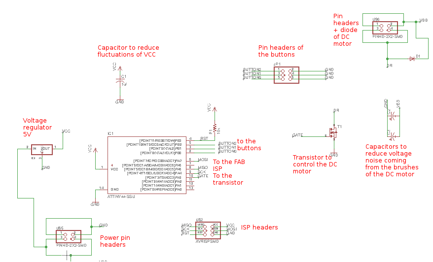
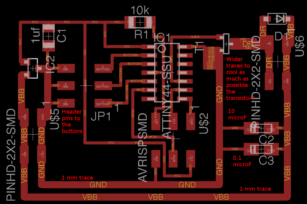
I drew the schematic in Eagle.
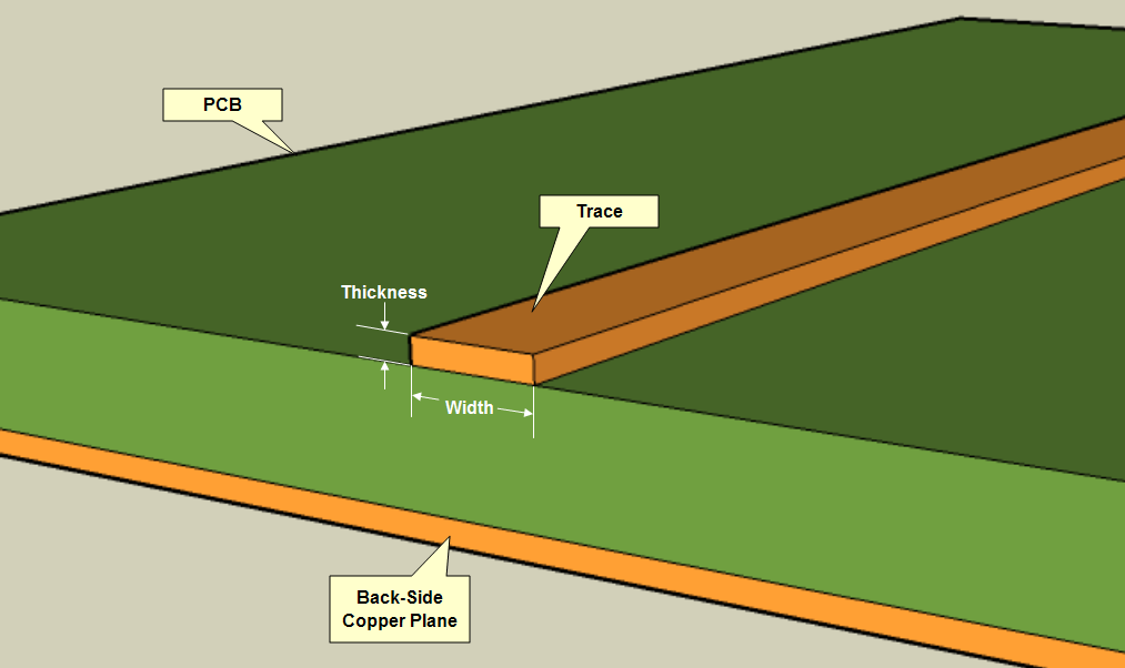
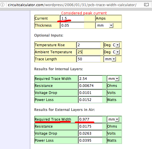
Considering the relative high voltages and currents when a DC motor is present, I checked the dimensions of the traces with tool that I found on-line.
I considered a peak current of 1,5A and the tool suggested me a trace of 1mm wide.
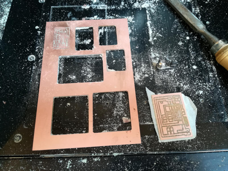
I cut all my last n.6 boards carefully using all the material available.
Then I solder all the components. I had to desoldered the ATTiny44 because I soldered two pins together.
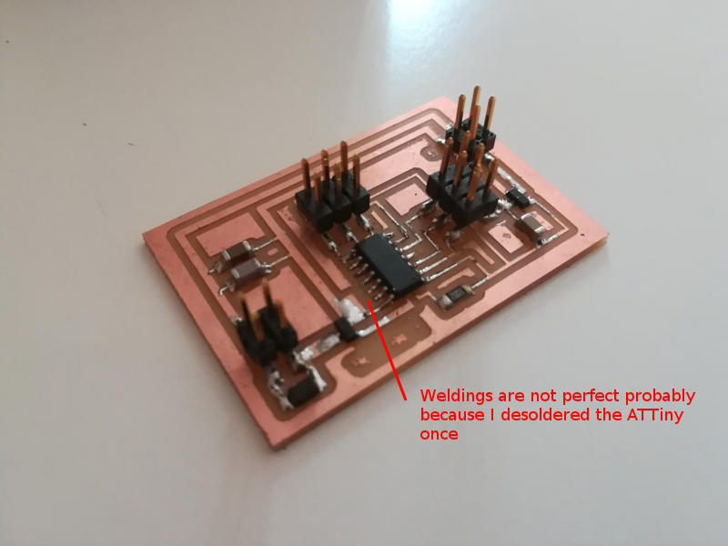
When I tried to program this board (see the programming part below) I didn't get proper signature by the Attiny, so I resoldered the weldings and I changed the Attiny but this didn't change the situation. I also checked with a multimeter all the connections.
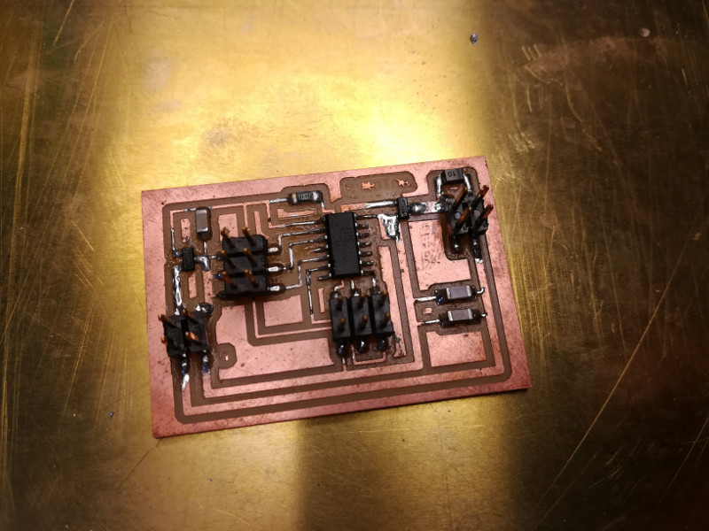
Below the board resoldered.
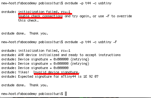
Flashing new board (failed)
I had a problem when I tried to program my board: my FabIsp was not able to comunicate with the ATTiny44 on my new board. I Checked the traces and connections with my multimeter and I didn' find anything strange.
I asked for help to my tutors and Fiore Basile suggested me to do this checks:
1) Check the weldings doing them again --> I heated them, I resoldered them and I also replaced the attiny
2) Try the Fab Isp on an other board --> done, Fab Isp works fine
3) Check the diodes --> done, diode with right direction
4) Ribbon cable is well connected? --> yes, it is
5) Check external clock and fuses --> mm.. I don't have external clock and I never changed the fuses..
But at the end I had the same problem of comunication between Fab Isp and the board.
C code
I never wrote a code in C before the Fab Academy and during Exercise n.8 and Exercise n.10 I wrote some new code in C language but they were quite simple. This time I have to do something a bit more complex.
I should study by my own at least how to use the registers related to clocks and PWM and I should be able to use properly the if statements.
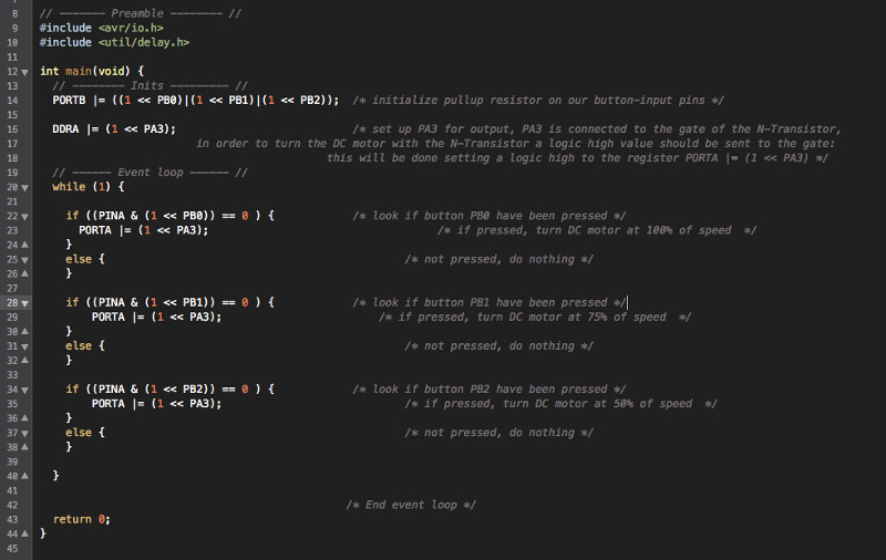
I started from something that I already knew form previous examples. So first I set the register PORTB to initialize the pull-up resistors on the pins connected to the buttons.
I set DDRA to logic high on the pin PA3 that will be connected to the gate of the N-channel transistor.
I tried to write down the routine with the if statements that will manage the different speeds of the DC motor through the buttons, but I found it too hard for my knowledge and so I asked for help to our italian Guru Fiore Basile and to my tutor Enrico Bassi. But they didn't help me as I expected: Fiore just sent me this link and Enrico this link.
It is 5th of July 2017, more than five months from the beginning, few days from the finish and my belif in the Fab Academy wasn't so low than today. I started with all my best whishes in this experience but now I can say that some parts has revealed worse or equal to any mediocre provincial univeristy. In particular some teachers and people around them don't care about the growth of their students, they have forgot the ethical values that education and scientific people should defend and conduct.
But I will not stop, I will not leave. I will continue studying this marvelous subject that is Science.
Reading from Make: AVR programming book I think I can't use simply a _delay_ms() function for my code, because it will use all the CPU power. Probably the CPU will not be able to read the zero values form the pins connected to the buttons because it is busy with the delay function. I probably need to use the internal timer/counter peripheral.
Timer/counter means that it can count the ticks from the system clock which are then stored in a register (TCNTn).
I will then store a number as comparing value in the Output Compare Register (OCRn) to get an elapsed time, frequency or duty cycle, freeing up the CPU.
When the compare value is reached it will be triggered the Waveform Generator that depends on the waveform mode and the output mode.
Output mode will be chose depending if I want to set, clear or toogle pins.
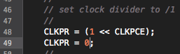
At this point I needed to study more about clocks in the AVR chips. Reading from the same book, there are multiple clock in the chip, all derived form the same common timebase but often divided down through their own individual prescaler. The internal RC oscillator runs around 8 MHz. The CPU clock is then divided down from the master clock, and runs at 1 MHz by default, even if it can be bumped up to 8 MHz. We say that we are burning fuses and we do this with AVRDUDE just like programming any other flash memor on the chip (see Make: AVR programming pag.193 for more details).
There is also a way to change the CPU clock through software and in particular with the Clock Prescale Register CLKPR (see pag.194) that also Niel uses in the code of the board DC motor with H-bridge of my Exercise n10 - Output devices. In the example he set the speed of the CPU from the default 1 Mhz to the maximum 8 Mhz:
From the c code:
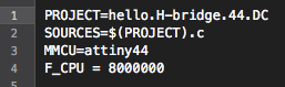
From the makefile:
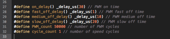
Now with this new knowledge I tried again to change the values in the code to see if I can turn the DC motor at different speeds. This time I was able to do it by changing the number of PWM cycles from 20000...

...to 50000 because the default value was too short and the DC motor didn't have time even to start turning...

I also changed other values in order to have wider difference between velocities and only one cycle per each speed.
The original code:
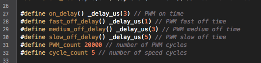
The modified code with the new values:
Finally my fan was able to turn at three different speeds:
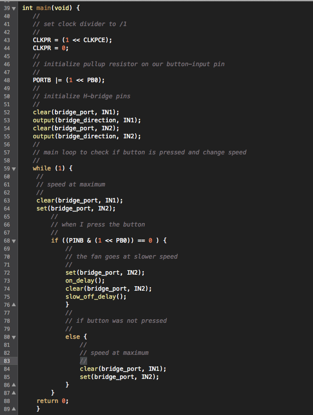
With all these new knowledge I was able to add the part of input to my code!
I set an internal pull up resistor on pin PB0 where the button will be connected.
I initialized the output pins IN1 and IN2 connected to the H-Bridge.
In the main loop I wrote a routine that statrs the motor at maximum speed ant checks if the button is pressed, in this case the motor slows down.
Here below the new part of my code!
In the video I show the new code working.
The impeller starts at maximum speed and when I press the button it slows down!