Week #8 EMBEDDED PROGRAMMING
Assignment
Softwares used
- AVR - C
- Processing
Environment used
- Text Editor-MousePad
- Arduino IDE
Read a microcontroller data sheet
I have read on one of the electronics forums that "Referring the data sheet is the old school way".Delving right into the very basics of how the microcontroller take in information , process them and give an output, is something than sparked my curiosity, and I was thrilled to do the "ols school way"..:P
What I learned from the Data Sheet
ATtiny24/44/84 is a low-power CMOS 8-bit microcontroller based on the AVR enhanced RISC architecture. By executing powerful instructions in a single clock cycle, the ATtiny24/44/84 achieves throughputs approaching 1 MIPS per MHz allowing the system designer to optimize power consumption versus processing speed.
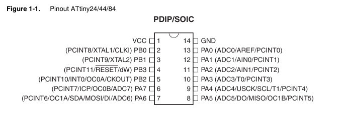
From the pin outs its evident that there are broadly 4 kinds of pinouts,the Vcc (Power Supply),GND (Ground),RESET, PORT A and PORT B.
- PORT A:
- PORT B:
Port A is a 8-bit bi-directional I/O port with internal pull-up resistors (selected for each bit). The Port A output buffers have symmetrical drive characteristics with both high sink and source capability. As inputs, Port A pins that are externally pulled low will source current if the pull-up resistors are activated. The Port A pins are tri-stated when a reset condition becomes active, even if the clock is not running.
Port B is a 4-bit bi-directional I/O port with internal pull-up resistors (selected for each bit). The Port B output buffers have symmetrical drive characteristics with both high sink and source capability

Then I understood from the above flow diagram, that PORT A has Analog to Digital Convertor capability whereas PORT B doesnt have.
Because I am new to the world of ICs and electronics, I have doubts on what are pull up and pull down resitors , also on how ADC's work. On studying the above flow chart, I would like to learn the workings of a watchdog timer, and how interupts are used.
Program your board to do something
There were lot of options , on which to code the program,I decided to learn from the fundamentals.Therefore, I took up to learning C and also flashing the files onto the bard using terminal command rather than other interfaces like arduino or other Graphical interfaces.
Using AVR C
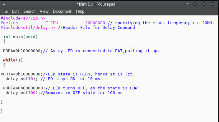
The first program I tried was to Blink the LED at a specific time periods.
How I flashed it onto the board.
- The microcontroller undertands the .hex format, however as I have written my code in ,c format we need to convert it.
- There are couple of steps in converting them:
- avr-gcc -g -Os -mmcu=attiny44a -c (filename).c
- avr-gcc -g -mmcu=attiny44a -o (filename).elf (filename).o
- avr-objcopy -j .text -j .data -O ihex (filename).elf (filename).hex
- sudo avrdude -c usbtiny -p t44 -U flash:w:(filename).hex
- NOTE# Dont include the brackets for filename.
This command would convert the file in .c format to .o format
Thias command would convert from.o format to .elf format
This command would convert from .elf format to .hex format.
This command would flash the .hex file onto the attiny44 chip.
What I learnt.
By doing this simple program, this is what I learnt:
- Understood the need for header files
- Understood how to write a programme in C language.
- Understood how the state of the pins are assigned.
- What DDRA, PORTA, actually means ,and how it can be used to program a code.
- How to flash the program unto the board using terminal commands.
Using ADRUINO IDE
Now, I wanted to try the same program in Arduino IDE.
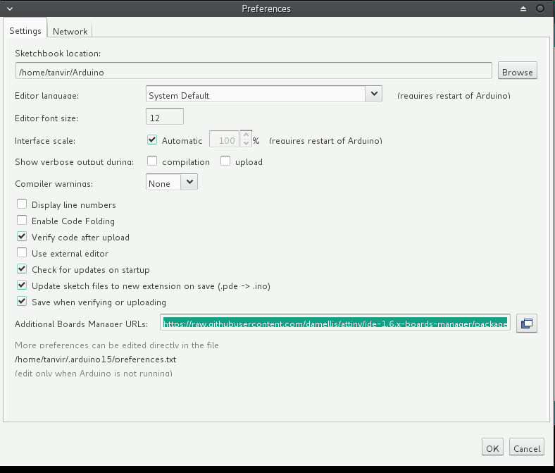
To get started with Arduino IDE, we need to first setup the attiny boards in the available set.
For this follow these steps:
- File->Preferences
- Under the "Additonal Board manager" blank fill in "https://raw.githubusercontent.com/damellis/attiny/ide-1.6.x-boards-manager/package_damellis_attiny_index.json"
- Click "OK" and exit.
- Go to Tools->Board:
- Select "Board Manager", which is on the top.
- Scroll down the dialog box that appears, and select "attiny", and install it.
- Tools-->Board:ATtiny24/44/84
- Tools-->ATtiny44
- Tools-->External 20Mhz
Having done this much, would ensure that all the details of the tiny44 chip which we have is there in the IDE now and the parameters are set in the settings.
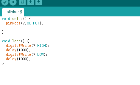
The logic behind the program is the same from the C program i have written earlier, however, the language used is much more user friendly.
My instructor, told me that , that all this were just a "mask", behind which is a very simple language (assembly).
Once the program has been written, we need to send it to our board, for this :
- Go to Tools--> Burn Bootloader
- Sketch--> Verify/Compile
- Sketch--> Upload
Having done this much the, file would be compiled and flashed unto the board.
What I learnt.
- Basics of Arduino programming language.
- How to get started with loading new boards
- How to flash the program into the board.
Download Files
The .c source code for the blink program can be found here.
The .ino arduino code for the blink program can be found here.
Now, that I have tried a very basic program , I wanted to do a program that could use both an input as well as an output.
For this, I wanted the LED to be lit when I pressed the switch.
Using AVR C
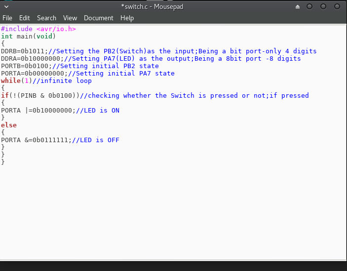
What I learnt.
- For excecuting this program I had to learn the basics of bitwise operators and how it is used to
- Initilly, I had given in the else loop, PORT A |=0b01111111; this however, yielded the result that the LED was lit the whole time after the initial button press.
- I understood that this was because of a wrong bitwise operator, instead of AND, I had used OR, and the operation meant that else loop really didnt change the state of the LED.
- How to define the required pins as input or output
- How to set the initial state of the pins.
- Working of an if else loop.
Using ADRUINO IDE
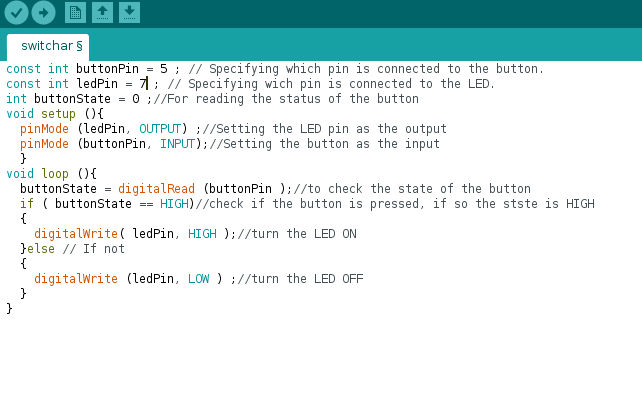
What I learnt.
- How to set the pins required as input and output
- How a condition is checked
- Working of an if else loop
Download Files
The .c source code for the switch program can be found here.
The .ino arduino code for the switch program can be found here.
Having done some basic input output and cliched examples in programming, I wanted to try something a bit more advanced
For this I did a Pulse Width Modulation (PWM),based program
I wanted to adjust the brightness of the LED.
Using AVR C
To get started on understanding how the PWM works and how to program one I reffered to an excellent tutorial
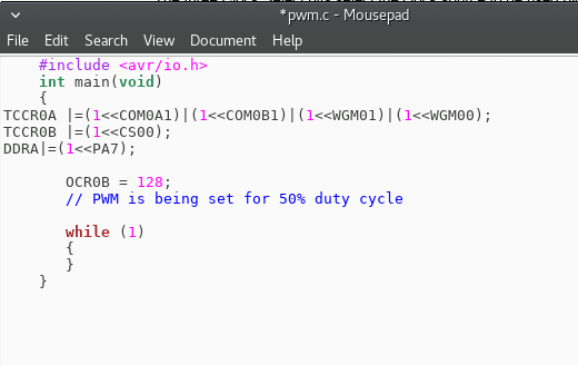
I have used a Fast PWM mode, for executing this program.
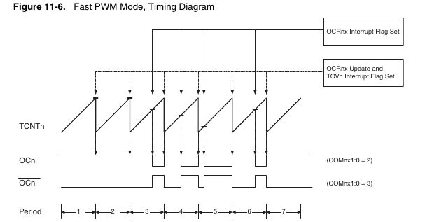
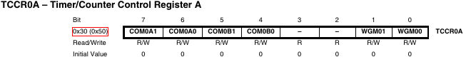
Now, refereeing to the Data Sheet for TCCR0A register we see,that:
Now, referring to the tables from 11-2 to 11-8, we get the values as;
- COM0A1:1
- COM0A0:0
- COM0B1:1
- COM0B0:1
- WGM01:1
- WGM00:1
The duty cycle can be calculated by the formula below:
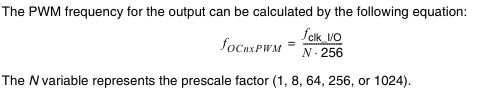
So, in the above formula to address the prescaler (N), we have to define the TTCCR0B
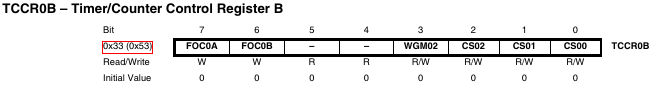
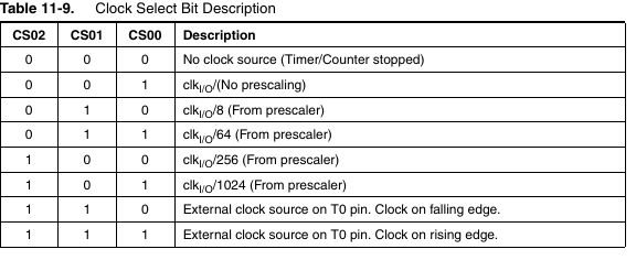
For defining the Clock Select bits refer to the table 11-9 , as shown below:
- FOC0A:0
- FOC0B:0
- WGM02:0
- CS02:0
- CS01:0
- CS00:1
My LED was connected on PA7, which is a OCR0B (Output Compare Register B)
What I learnt.
- Working of PWM
- Uses of Timers and Output counters
- What registers are and interrupts are.
Using ADRUINO IDE
Having achieved different brightness based on the value of duty cycle, I wanted it t have a continous increase and further decrease in brightness, for this i will be using Arduino IDE.
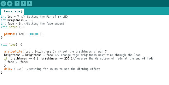
What I learnt.
- How to give function, to get an increase and decrease in brightness
Download Files
The .c source code for the PWM program can be found here.
The .ino arduino code for the PWM program can be found here.
Conclusion
As I was completely new to Programming, This was great introduction week.I learnt how to program with C language, and also understand the backgrounf working of flashing a program onto a board.C programming gave me an insight into programming in the very basic level.However, Processing language used in Arduino is somewhat easier to understand, for a first time user.