Exercise 10
Add an output device to a microcontroller board you've designed and program it to do something
How to build your own Arduino - Lesson of Mattia (Thursday)
The topic of the lesson was how to build our own Arduino compatible board. There are several options available:
- On the web page of Arduino.cc we looked at the tutorial Building an Arduino on a breadboard.
- An other option is the Fabkit page in the archive of Fabacademy.
- The Satshakit (also here) is a simplified version of the Fabkit and it has been developed by a student of the Fabacademy.
Suggestion of Mattia was to understand what we will do this week and prepare the connections for the output components.
He suggested to stard with an Arduino made by us with an ATMEGA and then use the Arduino IDE to program our boards.
He shows the page of Saverio Silli who made a separate board to control a DC motor during year 2015.
He told us that Farnell is normally delivering electronic components in one day.
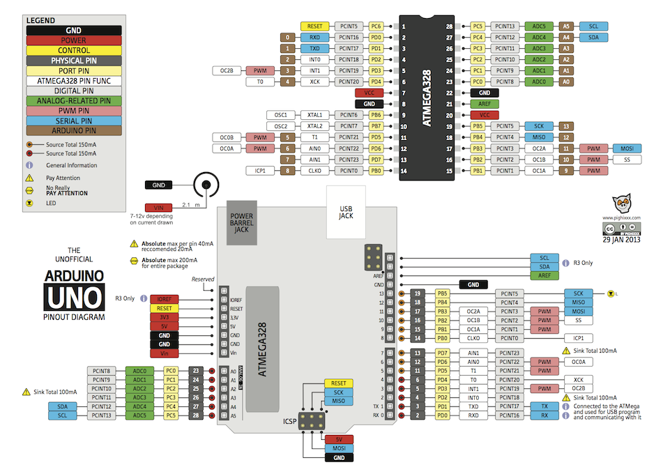
A good to have handy was the pin out layout of an Arduino UNO:
Programming with C code (Friday)
I have tried to program a board with makefiles. I didn't have chance to do it during the n.08 assigment Embeded Programming. You can fin this part on the page of the .
Making my own Arduino compatible board (Saturday)
Some back ground
I started from the Satshas project. At the beginning my idea was to build a Fabduino and then connect on a breadboard all the components to try them with the examples of the Arduino Starter Kit. After that I wuold build a special board to control a DC motor.
I downladed the schematics to made the board with the new laser machine. Schematics here and Board layout here.
But before I tried to figure out as much as I could on how the board is made. To do so I read again carefully the tutorial Building an Arduino on a breadboard and I tried to find the same components on the Satsha kit.
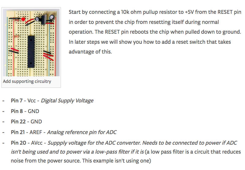
This part shows to the pin connections to the ATMEGA and the pullup resistor on the reset pin to avoid resetting the microcontroller when not needed.
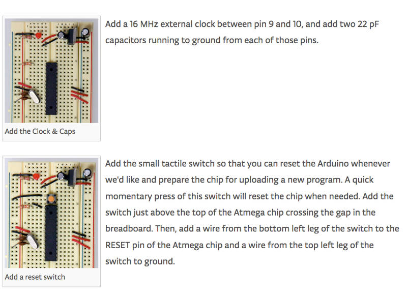
Then the crystal and the botton to reset the microcontroller.
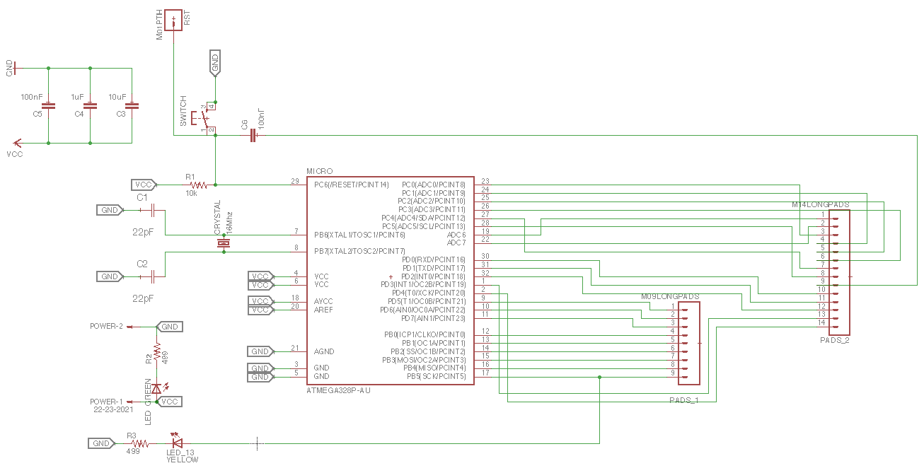
Here the schematics of the board.
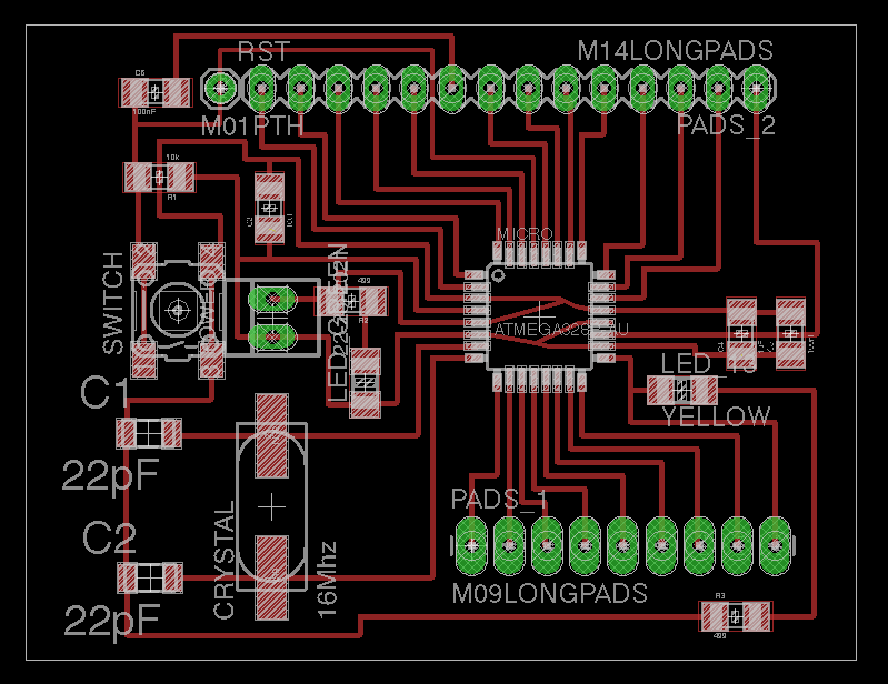
Here the layout of the traces in Eagle.
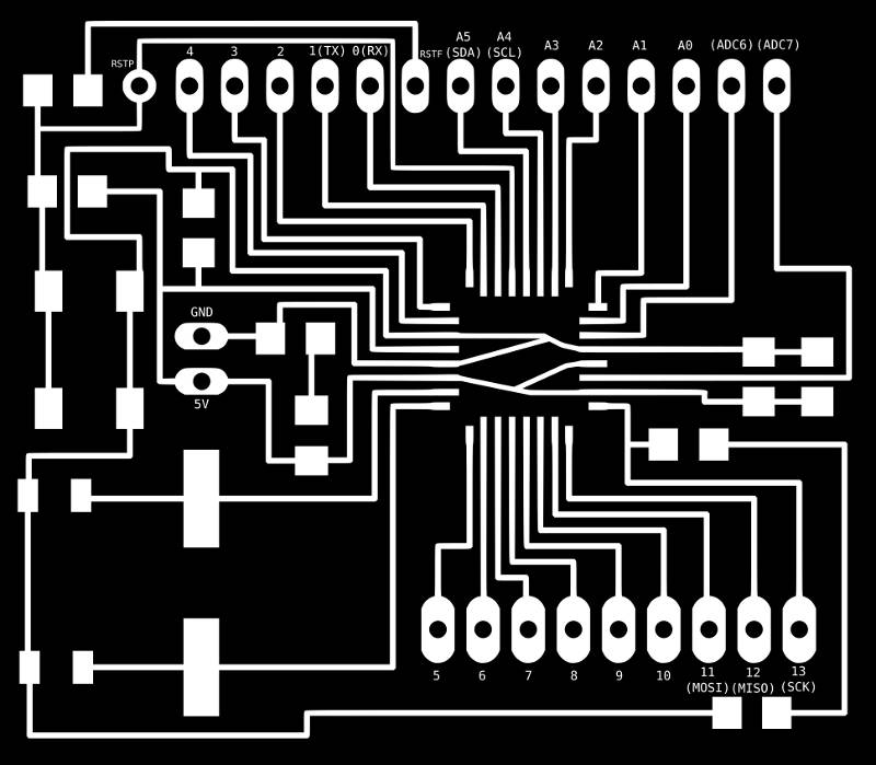
Here the layout of the pins in Arduino.
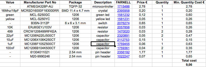
Click Here to download the list to the components for the board.
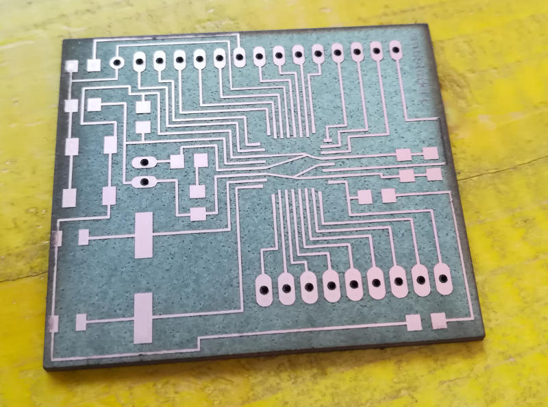
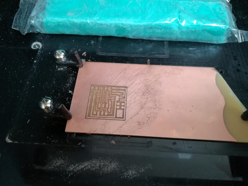
Laser cutting
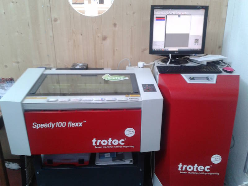
Before laser cutting the board I read the tutorial Laser Cutting a PCB with a CO2 / Fiber Trotec laser cutter available in the Fab Academy archive.
This was the result:
Output - controlling a motor with a H-Bridge (Monday)
I looked for some reference to build and control the the motor of the fan of my final project.
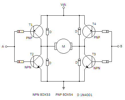
I found useful the projects N.09 Motorized Pinwheel and N.10 Zoetrope from the Starter Kit of Arduino. They theach how to connect DC motors to make them spin and how to control them through PWM. So first example is useing a transistor and second one is useing a h-bridge which is composed by four transistors.
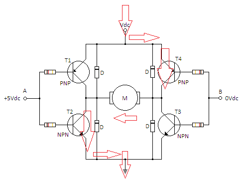
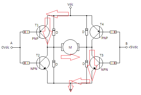
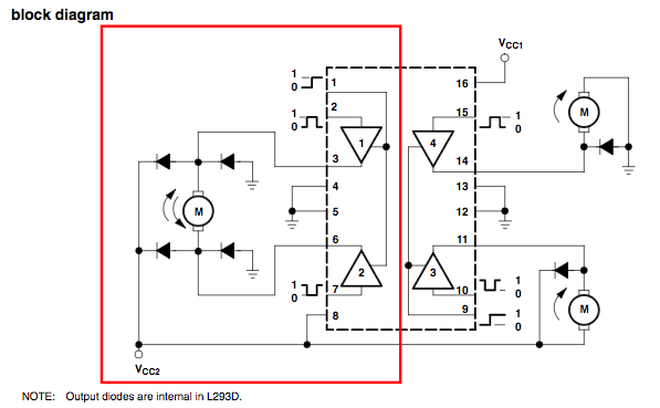
I searched for more information about how to manage motors through a h-bridge and an Arduino board and in particular this tutorial. H-bridge is mainly useful to turn the motor in both directions. It is made by four transistors which allow the current to flow in two different directions.
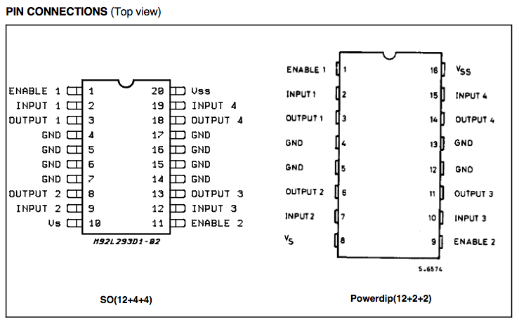
I did a bit of research and regarding the model L293 used in the example above I found two different layouts: one is surface mounted and one is through hole. They are equal in the behaviour except for the number of the pins in the center used for the heatsinking.
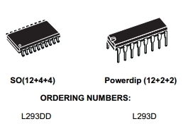
From the data sheet:
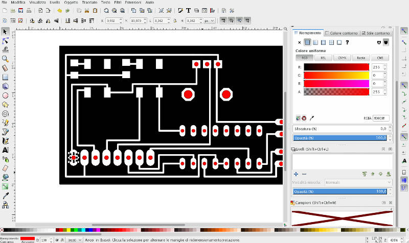
I exported the motor board in Inkscape where I followed again this tutorial.
Arduino code (Tuesday)
First variables are declared.
const int controlPin1 = 2; // connected to pin 7 on the H-bridge
const int controlPin2 = 3; // connected to pin 2 on the H-bridge
const int enablePin = 9;   // connected to pin 1 on the H-bridge
const int directionSwitchPin = 4;  // connected to the switch for direction
const int onOffSwitchStateSwitchPin = 5; // connected to the switch for turning the motor on and off
const int potPin = A0;  // connected to the potentiometer's output

// create some variables to hold values from your inputs
int onOffSwitchState = 0;  // current state of the On/Off switch
int previousOnOffSwitchState = 0; // previous position of the on/off switch
int directionSwitchState = 0;  // current state of the direction switch
int previousDirectionSwitchState = 0;  // previous state of the direction switch

int motorEnabled = 0; // Turns the motor on/off
int motorSpeed = 0; // speed of the motor
int motorDirection = 1; // current direction of the motor
Then the function void setup() to set the pin modes. This part will be run only once at the start.
void setup() {
  // intialize the inputs and outputs
  pinMode(directionSwitchPin, INPUT);
  pinMode(onOffSwitchStateSwitchPin, INPUT);
  pinMode(controlPin1, OUTPUT);
  pinMode(controlPin2, OUTPUT);
  pinMode(enablePin, OUTPUT);

  // pull the enable pin LOW to start
  digitalWrite(enablePin, LOW);
}
Then the function loop() is run continuously after void setup() is completed.
void loop() {
  // read the value of the on/off switch
  onOffSwitchState = digitalRead(onOffSwitchStateSwitchPin);
  delay(1);

  // read the value of the direction switch
  directionSwitchState = digitalRead(directionSwitchPin);

  // read the value of the pot and divide by 4 to get
  // a value that can be used for PWM
  motorSpeed = analogRead(potPin) / 4;

  // if the on/off button changed state since the last loop()
  if (onOffSwitchState != previousOnOffSwitchState) {
    // change the value of motorEnabled if pressed
    if (onOffSwitchState == HIGH) {
      motorEnabled = !motorEnabled;
    }
  }

  // if the direction button changed state since the last loop()
  if (directionSwitchState != previousDirectionSwitchState) {
    // change the value of motorDirection if pressed
    if (directionSwitchState == HIGH) {
      motorDirection = !motorDirection;
    }
  }

  // change the direction the motor spins by talking
  // to the control pins on the H-Bridge
  if (motorDirection == 1) {
    digitalWrite(controlPin1, HIGH);
    digitalWrite(controlPin2, LOW);
  } else {
    digitalWrite(controlPin1, LOW);
    digitalWrite(controlPin2, HIGH);
  }

  // if the motor is supposed to be on
  if (motorEnabled == 1) {
    // PWM the enable pin to vary the speed
    analogWrite(enablePin, motorSpeed);
  } else { // if the motor is not supposed to be on
    //turn the motor off
    analogWrite(enablePin, 0);
  }
  // save the current On/Offswitch state as the previous
  previousDirectionSwitchState = directionSwitchState;
  // save the current switch state as the previous
  previousOnOffSwitchState = onOffSwitchState;
}
Restarting from Niel's board (after week 10)
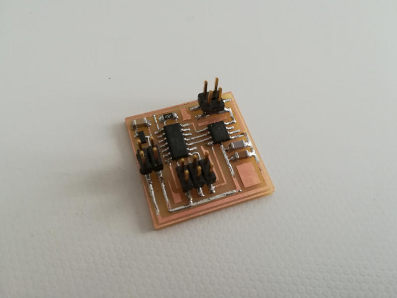
During the review with Fiore Basile he suggested me to try the Niel's DC motor board here below.
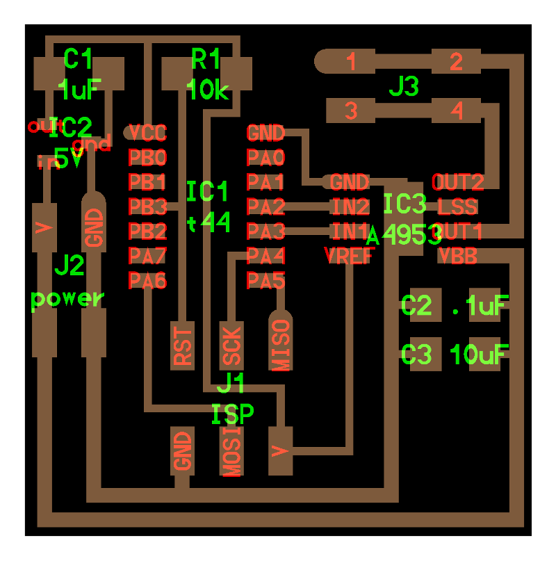
The components on this board are:
- 1x ATtiny44
- 1x 6 pin header
- 2x 4 pin headers
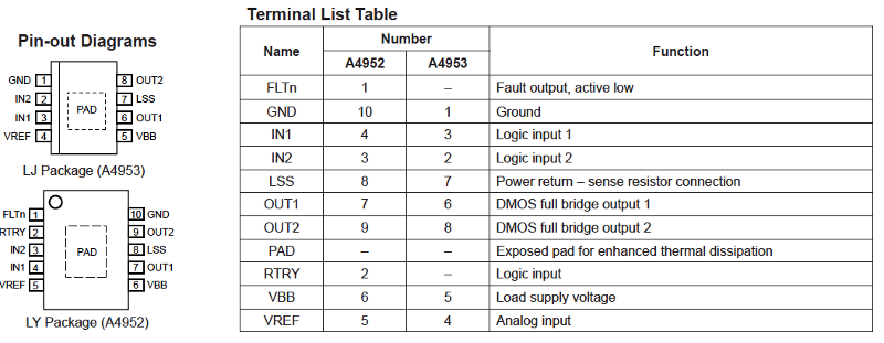
- 1x H-bridge IC3 A4953
- 1x 5V voltage regulator LM3480
- 1x 0.1 microF capacitor
- 1x 1 microF capacitor
- 1x 10 microF capacitor
- 1x 10K resistance
In particular here there is the pin out of the h-bridge.
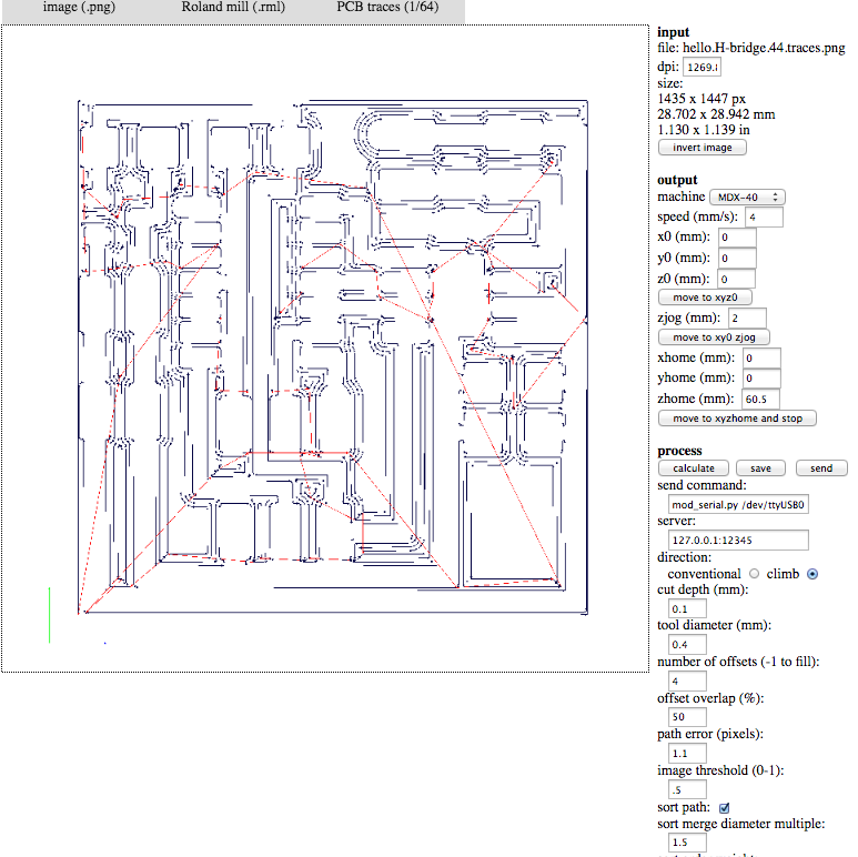
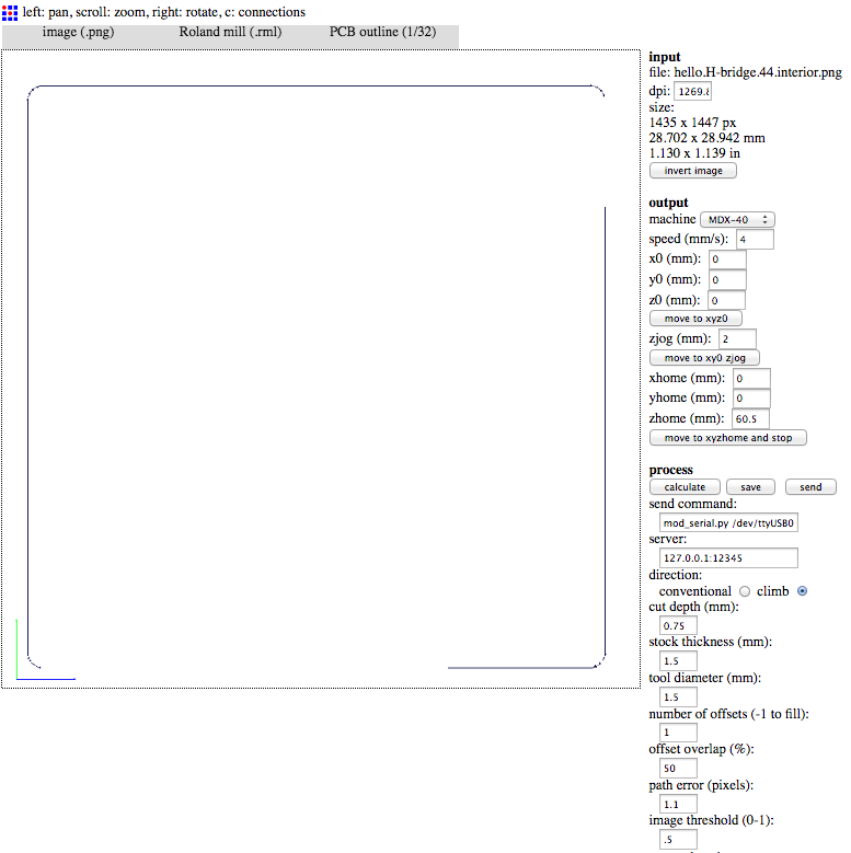
I downladed the traces and the border.
I opened them in the Fab Modules to create the .rml file with the module PCB traces (1/64). I followed same settings noted during the assigment 04.
Then the border throughPCB traces (1/32) following same notes of assigment 04.
I moved with Terminal in the folder with the files hello.H-bridge.44.DC.c and hello.H-bridge.44.DC.make taken from Fabacademy's archive.
I typed:
new-host:Hello-H-Bridge pablocolturi$ make -f hello.H-bridge.44.DC.make program-usbtiny
And I got positive answer:
avr-objcopy -O ihex hello.H-bridge.44.DC.out hello.H-bridge.44.DC.c.hex;\
	avr-size --mcu=attiny44 --format=avr hello.H-bridge.44.DC.out
AVR Memory Usage
----------------
Device: attiny44

Program:     544 bytes (13.3% Full)
(.text + .data + .bootloader)

Data:          3 bytes (1.2% Full)
(.data + .bss + .noinit)


avrdude -p t44 -P usb -c usbtiny -U flash:w:hello.H-bridge.44.DC.c.hex

avrdude: AVR device initialized and ready to accept instructions

Reading | ################################################## | 100% 0.01s

avrdude: Device signature = 0x1e9207 (probably t44)
avrdude: NOTE: "flash" memory has been specified, an erase cycle will be performed
         To disable this feature, specify the -D option.
avrdude: erasing chip
avrdude: reading input file "hello.H-bridge.44.DC.c.hex"
avrdude: input file hello.H-bridge.44.DC.c.hex auto detected as Intel Hex
avrdude: writing flash (544 bytes):

Writing | ################################################## | 100% 0.31s

avrdude: 544 bytes of flash written
avrdude: verifying flash memory against hello.H-bridge.44.DC.c.hex:
avrdude: load data flash data from input file hello.H-bridge.44.DC.c.hex:
avrdude: input file hello.H-bridge.44.DC.c.hex auto detected as Intel Hex
avrdude: input file hello.H-bridge.44.DC.c.hex contains 544 bytes
avrdude: reading on-chip flash data:

Reading | ################################################## | 100% 0.45s

avrdude: verifying ...
avrdude: 544 bytes of flash verified

avrdude: safemode: Fuses OK (E:FF, H:DF, L:62)

avrdude done.  Thank you.
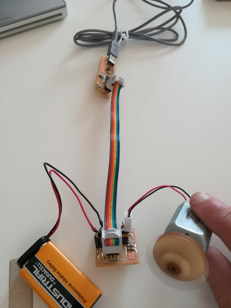
I connected everything but the motor didn't run.
I checked volts in the board with the multimeter and the power was OK, and also the ATTiny looked fine.
I checked also the ampers with the oscilloscope and they looked fine too.
I decided to modify the code in order to check easly the volts in the board. So I tried to leave only the part of the motor going forward. I am a beginner with "c" language so I didn't expect any good result, but everything worked perfectly.
// // // hello.H-bridge.44.DC.c // // H-bridge DC motor hello-world // // Neil Gershenfeld // 11/18/12 // // (c) Massachusetts Institute of Technology 2012 // This work may be reproduced, modified, distributed, // performed, and displayed for any purpose. Copyright is // retained and must be preserved. The work is provided // as is; no warranty is provided, and users accept all // liability. // #include#include #define output(directions,pin) (directions |= pin) // set port direction for output #define set(port,pin) (port |= pin) // set port pin #define clear(port,pin) (port &= (~pin)) // clear port pin #define pin_test(pins,pin) (pins & pin) // test for port pin #define bit_test(byte,bit) (byte & (1 << bit)) // test for bit set #define on_delay() _delay_us(3) // PWM on time #define fast_off_delay() _delay_us(1) // PWM fast off time #define medium_off_delay() _delay_us(3) // PWM medium off time #define slow_off_delay() _delay_us(5) // PWM slow off time #define PWM_count 20000 // number of PWM cycles #define cycle_count 5 // number of speed cycles #define bridge_port PORTA // H-bridge port #define bridge_direction DDRA // H-bridge direction #define IN1 (1 << PA3) // IN1 #define IN2 (1 << PA2) // IN2 int main(void) { // // main // static uint16_t count; static uint8_t cycle; // // set clock divider to /1 // CLKPR = (1 << CLKPCE); CLKPR = (0 << CLKPS3) | (0 << CLKPS2) | (0 << CLKPS1) | (0 << CLKPS0); // // initialize H-bridge pins // clear(bridge_port, IN1); output(bridge_direction, IN1); clear(bridge_port, IN2); output(bridge_direction, IN2); // // main loop // while (1) { // // turn forward // clear(bridge_port, IN1); set(bridge_port, IN2); } }
Here below to download the C code modified with costant speed:
And finally everything worked just fine! The motor turned forward and the level of voltage was correct everywhere on the board.
Three speeds DC motor board
After some weeks -working at the final project- I was able to modify the code of this week so that the DC motor turned at three different speeds. Please check Final Project - Electronics for more details!
New output DC motor board for final project
Please se also Final Project - Electronics where I designed a completely new DC motor board with a transistor instead of a h-bridge for the control of the impeller of my final project.