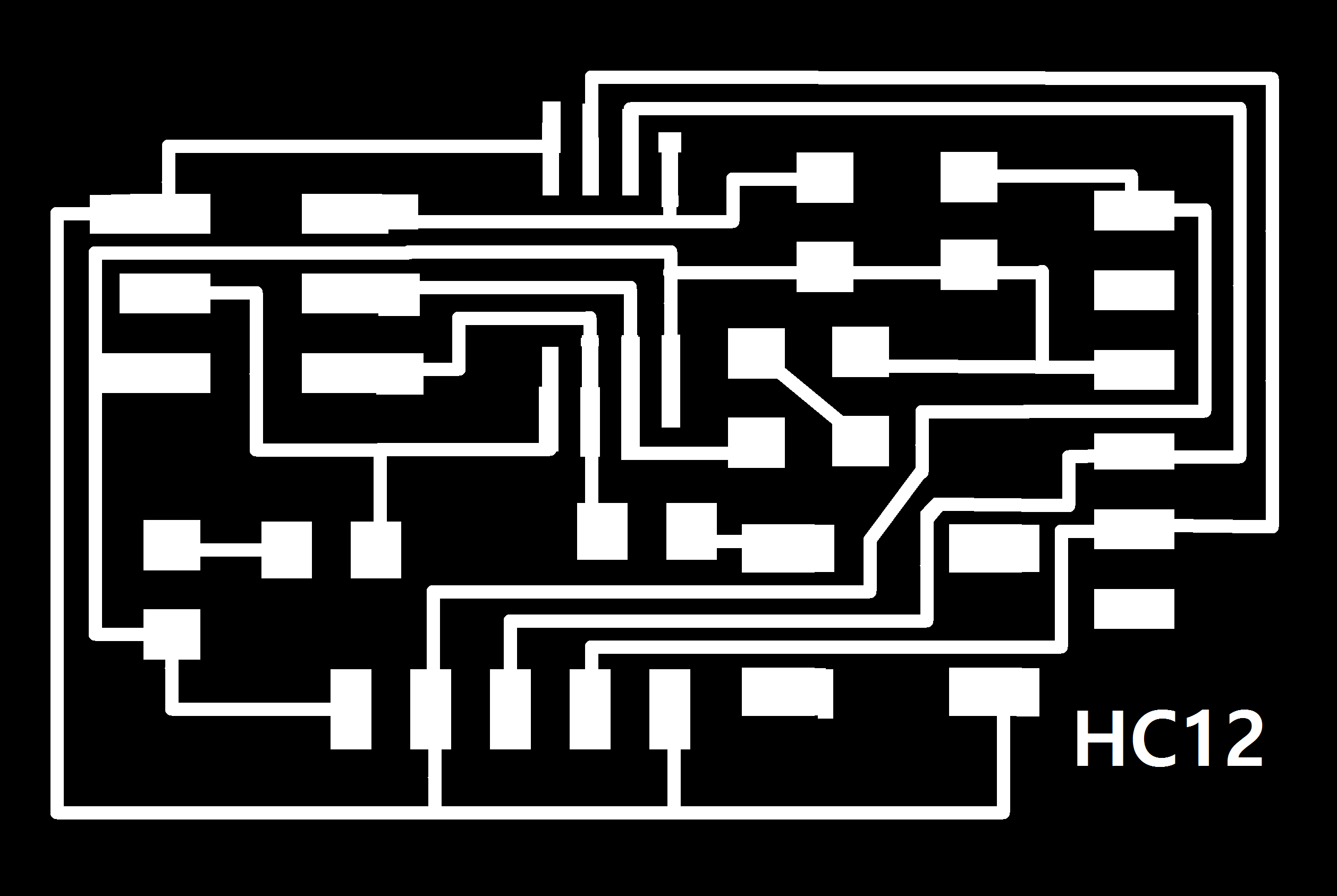
Download files here: Trace and Outline
Assignments:
 - Design and build a wired and/or wireless network connecting at least two processors.
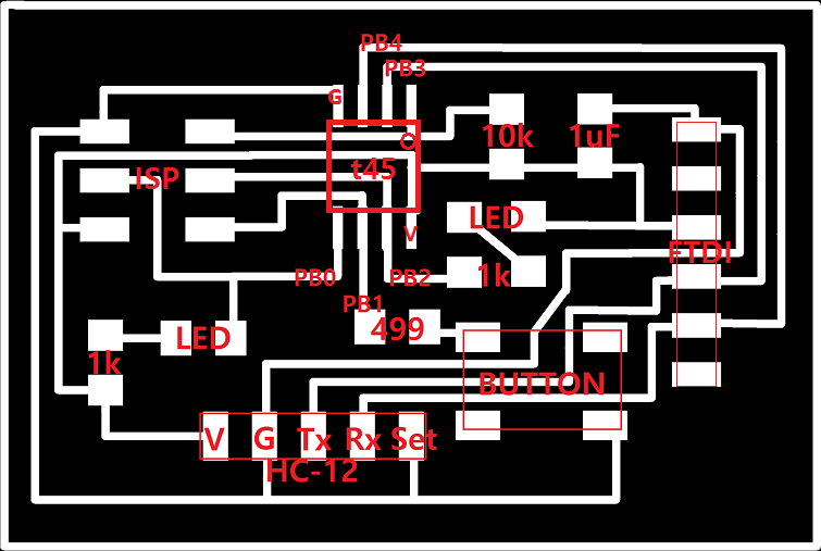
I designed boards for HC-12 and modified hello.bus.45.c (from serial bus/asynchronous)so that it works even for wireless connection.
- I printed out three bridges. The difference between bridge and node is that only bridge will communicate with computer as well, so it has FTDI connector. I just included FTDI connection for all bridges because it will be easier to detect any error to the bridge, and also replace it with one of the nodes.
Download files here: Trace and Outline
- Before starting, connect all HC-12 to FTDI (G-G, V-V, Tx-Rx, Rx-Tx, SET-DTR), open arduino serial monitor, type 'AT' to see if the configuration mode is on. I got help from this page: HC-12 command and used: 'AT' 'AT+DEFAULT' 'AT+B9600'
- Important notes for programming:
1. I should separately program each board with different node id: ex) bridge=id:0, node1=id:1,node2=id:2
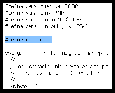 (hello.bus.45.c file)
2. The order of pin is different from HC12. (I didn't know which pin should be connected to which when designing.) For bridge, this should be kept since it has to communicate with FTDI, but for nodes, this doesn't need to be kept. Option 1: just connect carefully considering this order. Option 2: Code for nodes can be changed so that PB4 is connected to 'Tx', and PB3 to 'Rx' (for bridge, keep PB4-'Rx' and PB3-'Tx'). Both works fine.
3. With wire connection (no connection between 'SET'), hello.bus.45.c works fine, but with wireless connection, it didn't since it cannot send signal just by having high voltage and wire connection. After struggling, I figured out how to solve the problem. Now the bridge sends signal even when the input is not the same as its id.
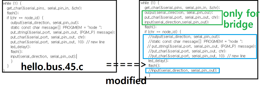
Download c code here: bridge and node. For option 2, change code for node: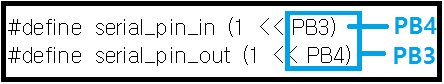
4. Depending on the files, modify the filename of Makefile. (Then 'make' and 'avrdude -p attiny45 -c usbtiny -U hello.bus.45.bridge/node.c.hex')
'
- After programming them, connect them ('Tx' to 'Tx', 'Rx' to 'Rx'). These 'Tx' is connected to 'serial_pin_in', and 'Rx' to 'serial_pin_out' in the codes. Also connect V and G for nodes.(white circles). (Option 1 and 2: red circles) 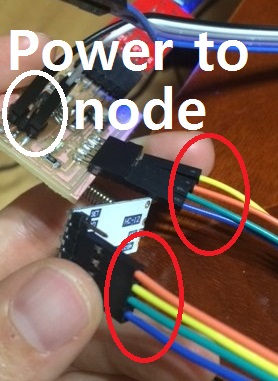 Bridge
 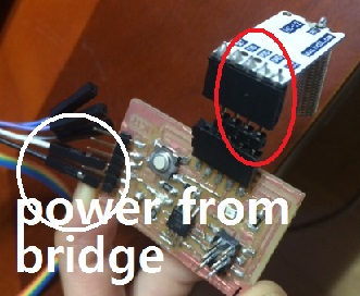 Node
Node
- Open arduino-->Serial monitor. Type 0,1 or 2 to see what happens.
Note:
- At first the networking didn't work, but I didn't know it's the problem of boards or the codes. Since bridge '0' was the only blinking one, I replaced it with node '1' and then '2', test them with FTDI, and then found out that node '1' and '2' have connection problem. So it seems better to have pins for FTDI just to find error easily.
- I failed to include button to the code since it was written in C, and for me, C is still very new and difficult. I will keep trying.
- Here is the schematics, and how it works:
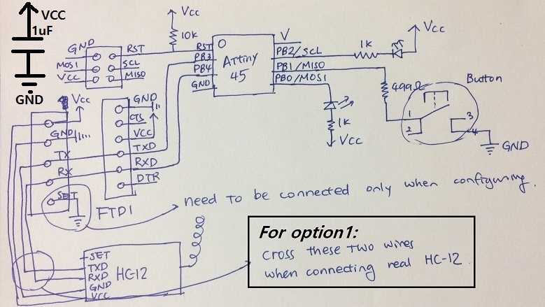 schematics
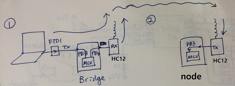 How it works (as far as I understand+roughly speaking): SPI(serial_pin_in) of bridge recieves signal('0','1','2',...) from FTDI, and then MCU of bridge send signal to SPO(serial_pin_out) of bridge, and it goes into 'Rx' of HC-12 of bridge and then into the air. HC-12 of nodes catch it, and send it through 'Tx' of HC-12 of nodes to SPI of nodes. It initiate the reaction of nodes.
