 -'Sun' by my son
I have lots of things that I want to make: Bike with a seat that can be pushed upright, water faucet that shows the amount of water running, musical chair, modular bed frame with pipe lamp(+planetarium), filament stool solar power generator with watch spring to track the sun, etc. I tried to improve the ideas to make real thing, but for now, I still feel lack of knowledge and experience especially in mechanical design. So I can go with something easier and doable this time, and then improve other things later. This can be a good excuse to stay around fablab even after graduation.
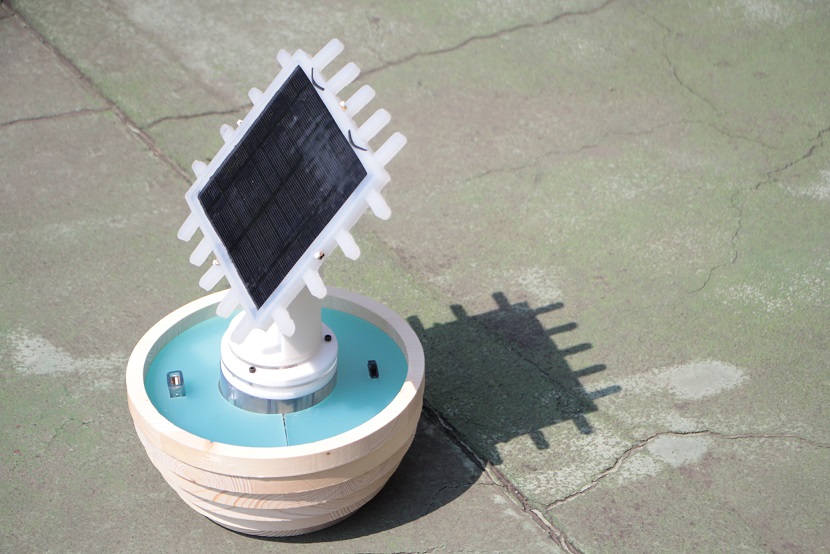
What I chose is a Sun-tracker (which will turn into a sun-bather later).
-'Sun' by my son
Components
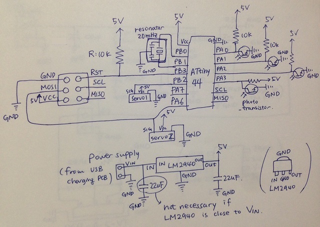
1. Main servo-phototransistor PCB
- ATtiny44, 10k Res(5), 22uF cap(2), 1uF cap, IC reg LM2940 5v, resonator 20mHz
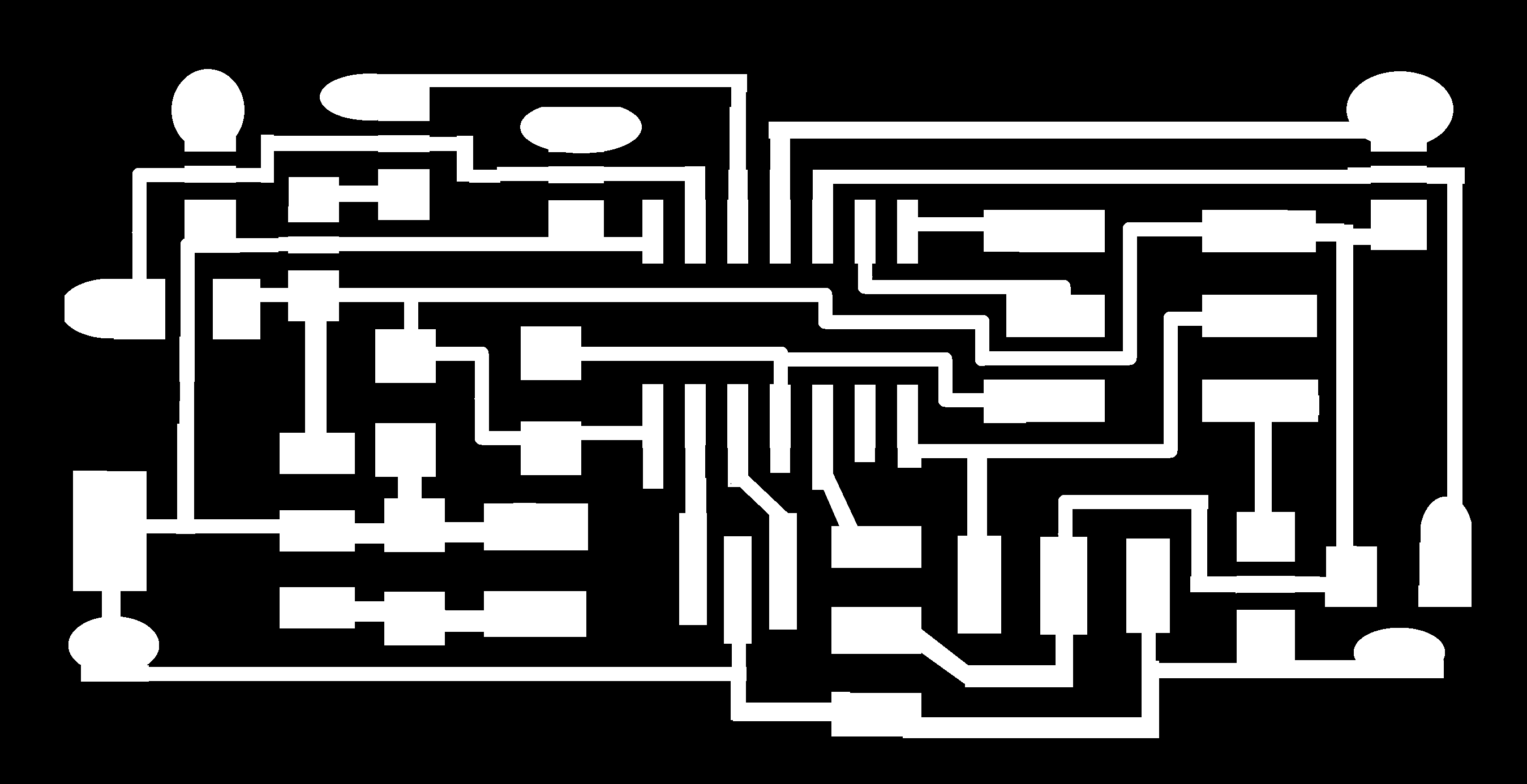
This is the schematic of this board:
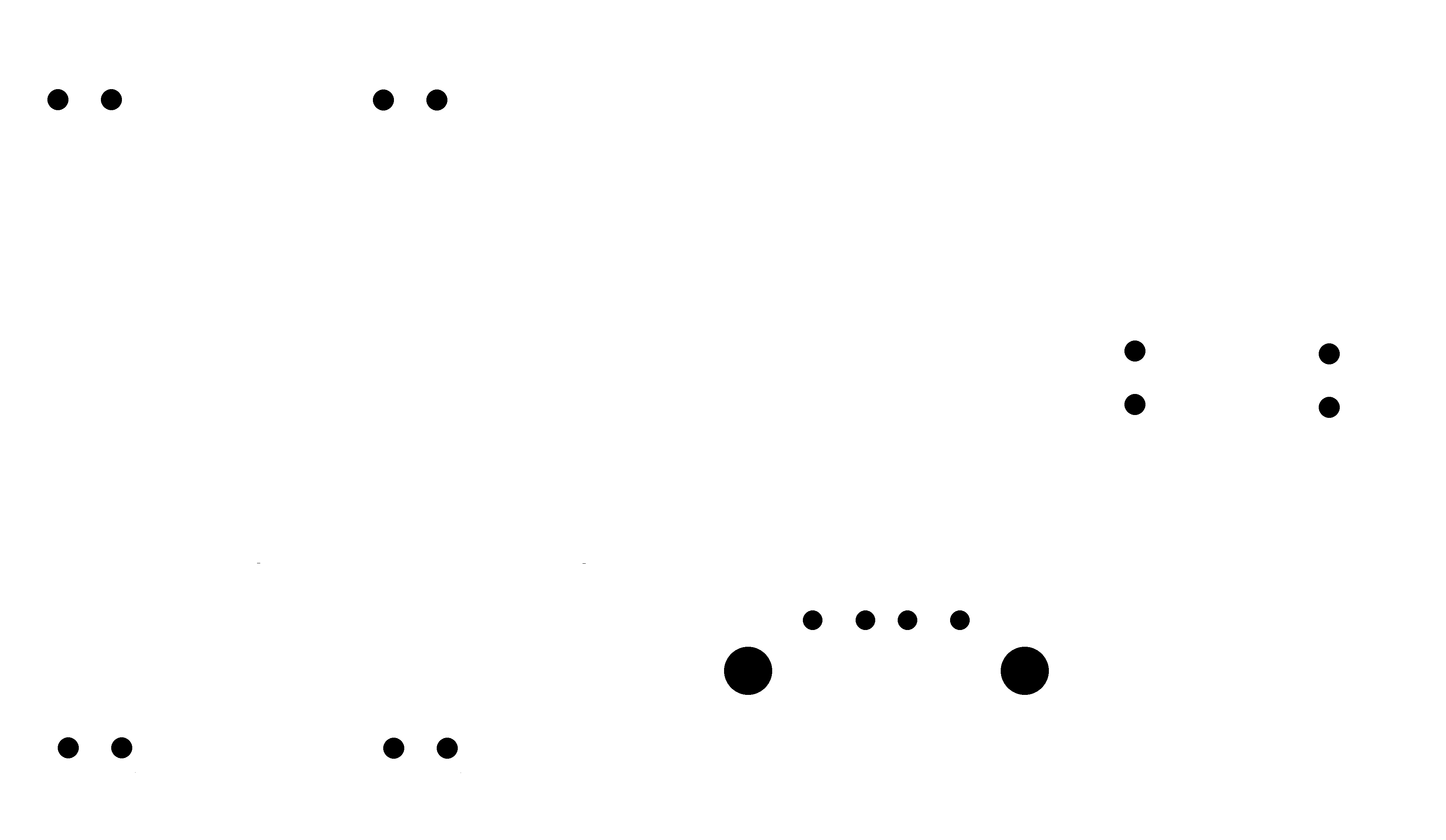
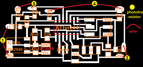 with phototransistors
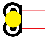 connected properly.
(This is what I mean by "properly".)
![]()
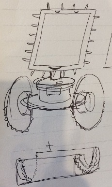
- One pair of phototransistor ear will work as a sensor for horizontal direction, and another for vertical direction. For each pair, phototransistors should be soldered biased (45 degree outward).
With all the wires connected: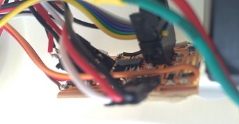
(Download files here: main PCB-trace, outline, and phototransistor-trace, holes and outline.)
2. Lipo charging PCB
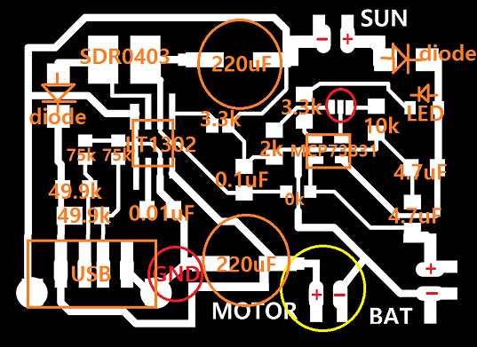
- First design: slight modification of SolarBag of Fablab Barcelona(here). Special thanks to Fablab Barcelona! 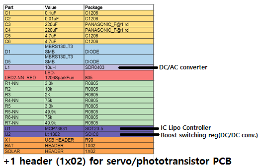
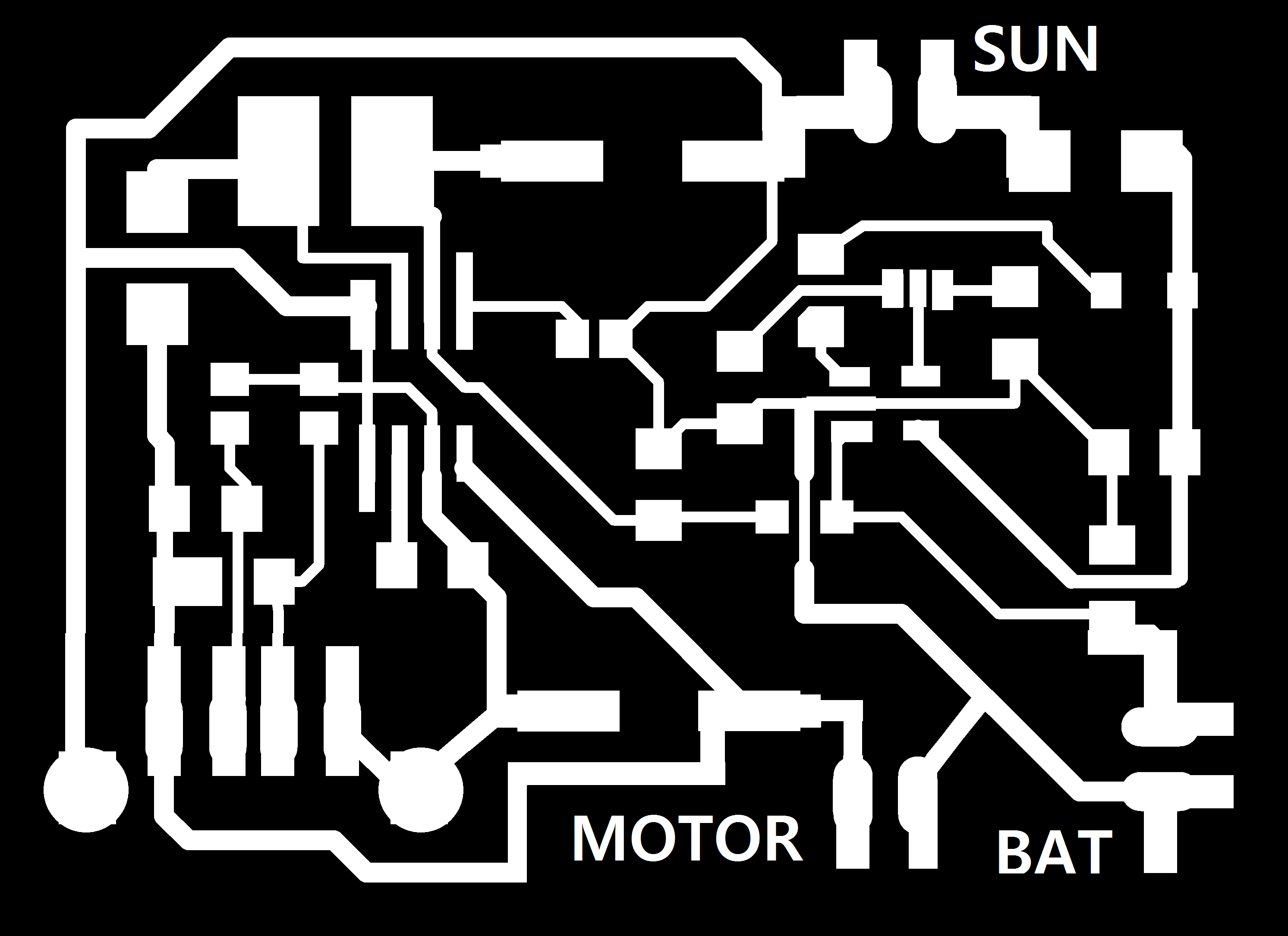
This design has both lipo charging circuit and usb charging system in one board. The trace file has to be fixed in one place (big red circle: GND should be connected), and I added wires (big yellow circle) so that the main PCB can get the electricity from this('MOTOR'). The small red circle is where I have to choose among 100mA(10k Res) and 500mA(2k Res). I disconnected 2k Resistor, and connected 10k Resistor just to be safe, but I guess it is okay to change it to 2k one later.
(Download files here:Trace, holes, and outline.
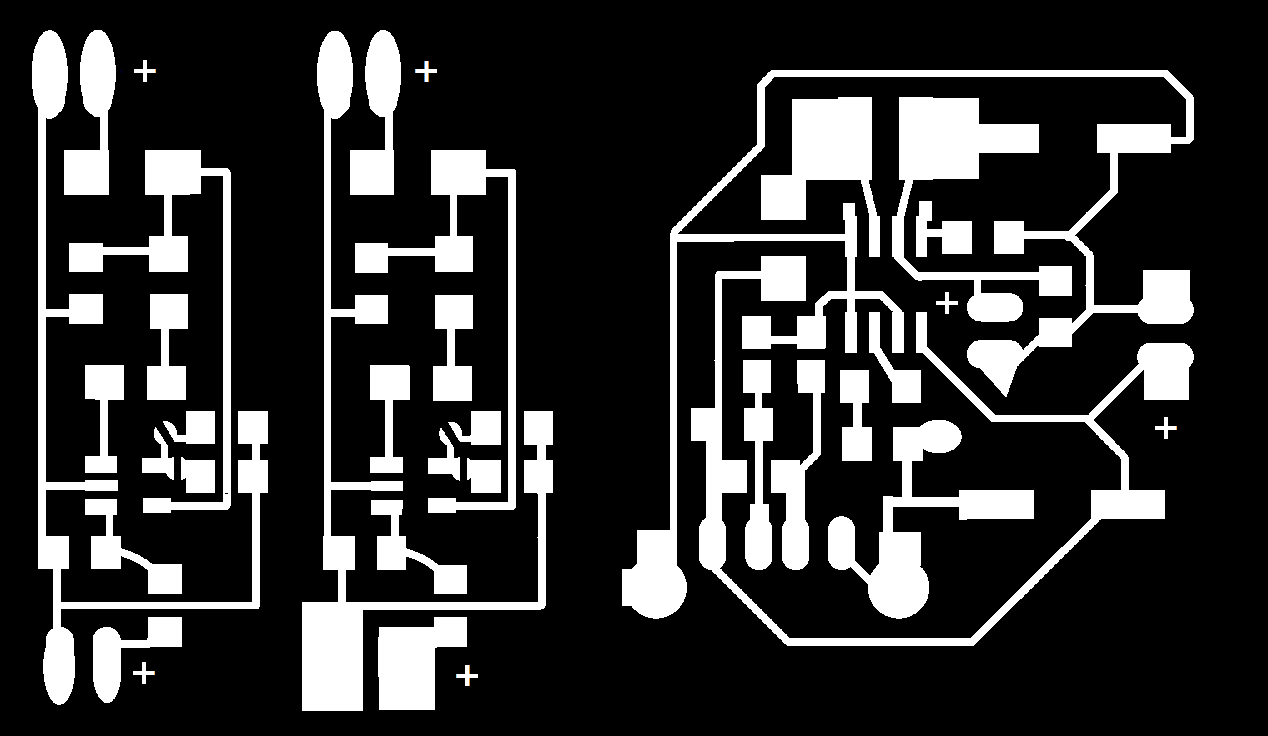
- Second design: This has two separate pcb in which one is for lipo charging and another for usb charging. (I drew these schematics based on the datasheets of MCP73831 and LT1302) 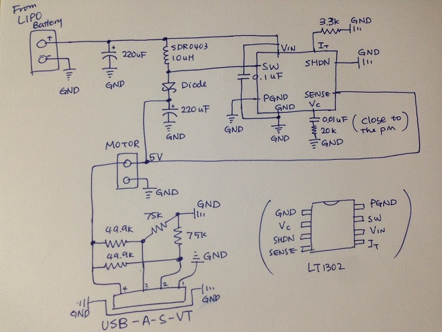 USB charging pcb schematic
 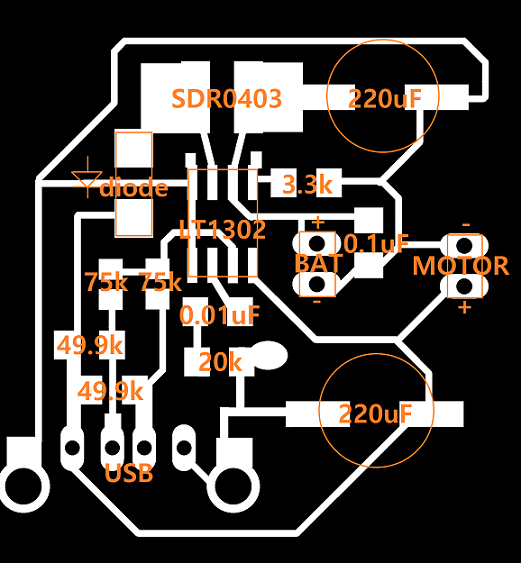 USB charging pcb board
 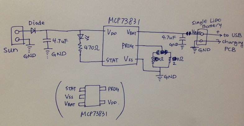 LIPO charging pcb schematic
 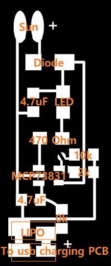 LIPO charging pcb board
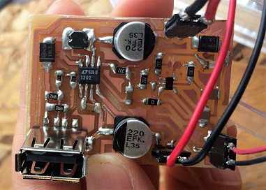
 USB charging
 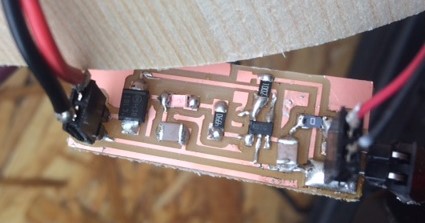 Lipo charging
(Download files here:Trace, holes, and outline.)
3. Two big Servo motors(Hobby HES 288) connected to the main PCB (S1, S2).
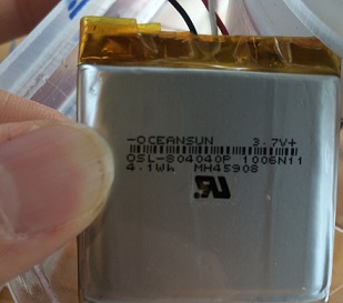
4. Lipo battery (3.7V, 4.1wh, 1100mAh)
 Download file here.
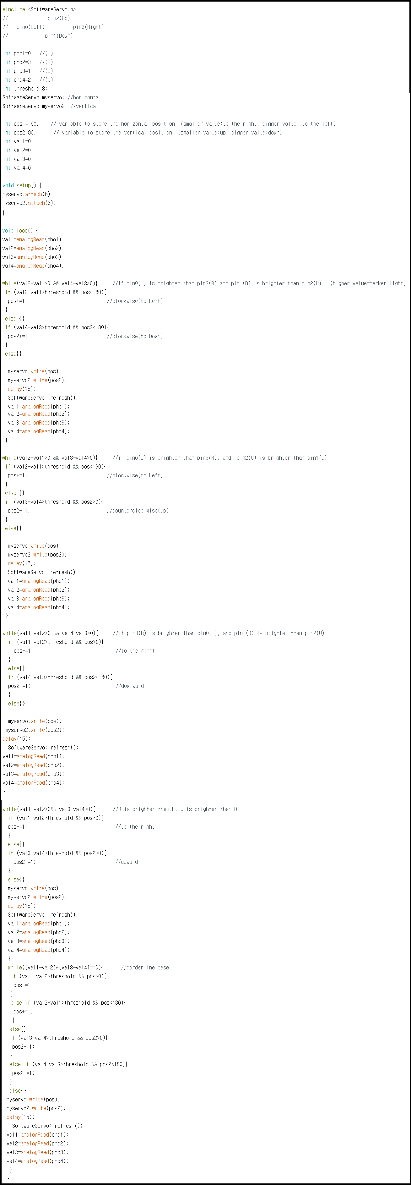
This code does:
1. Read values from all four phototransistors (1),(2),(3),(4).
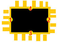
2. Compare (1) and (2), and if (1)-(2)>0 (<==> (1) is darker than (2)) and if the difference is noticable (that is, (1)-(2)>"threshold" where threshold can be some positive number), then turn clockwise towards (2) (<==> servo input gets higher). Vice versa.
(Do the same thing for (3) and (4).)
Note that I need to check for four cases:
For each case, to turn the servo motor (which can turn from 0 to 180 degree), also need to check if the servo motor is at the limit (0 or 180 degree).)
3. Used "SoftwareServo.h" ("Servo.h" cannot be used for ATtiny 44).
4. Used "SoftwareServo::refresh();"" every 15ms (at least every 50ms).
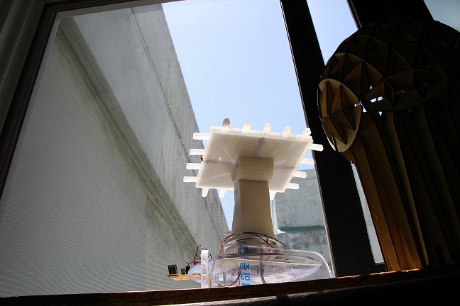
- Design: I designed back for the panel so that the panel can be attached to it by silicone case, and phototransistors can be also installed
 panel back
 panel back+panel
 panel back+panel+silicone case
- (3D printing)
I printed this panel back using 3D printer with the following settings, and it came out alright.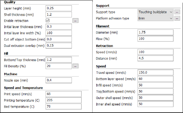
Four narrow paths are for the wires connecting phototransistors and main PCB. (And at each end, I soldered female header (1x2))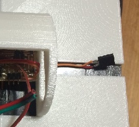
- (Molding and casting)
I designed a mold for silicone case and melt the wax chips to make a big box for it.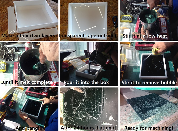
Note:
1. Spray release agent inside the box, and let it dry for 10 min before melting wax.
2. Since wax can be flamable, heat it slowly, and lower the heat if you see any smoke.
3. Use leather gloves to hold hot pot.
4. After 24hours, the wax got shrunken from 208x230 to 200x220 (the model:198x220).
5. Flattening: fix four pieces of wood with screw for each side. Set z origin at the highest point, and then cut 1mm. Repeat until it gets smooth (I cut 1.5x6=9mm)-now the mold is smaller in any direction. I had to modify the model.
6. Used 10mm endmill for flattening.
- Now let's make the case:
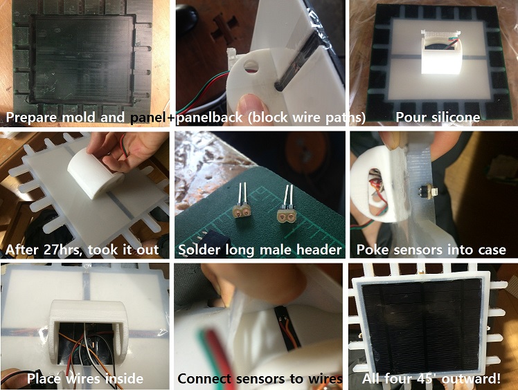
Note:
1. Used Aspire: rough cut-6mm, step over:20%, 10000rpm, feedrate 80, plunge rate 40. Didn't do finish cut.
2. Some broken parts while milling-maybe because it is recycled wax. (I found wood, silicone, etc. inside the wax.)
3. Amount of water for mold: a little more than 100g==>30% more, so used mold max 10T A:B=130g:13g (Pot life=45min, mixing time=3min, cure time=24hr (no vacuum degass since the mold wasn't deep enough after remodeling, and it might get spilt))
4. I used double sided transparent tape between panel and panel back, and it became really sticky. Not recommended.
5. Panel back used for casting is for one axis model (I will explain more later), so has only horizontal wire paths.
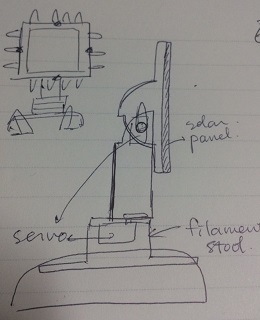
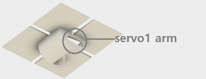
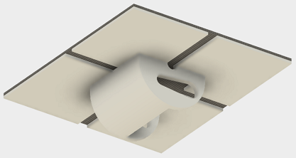
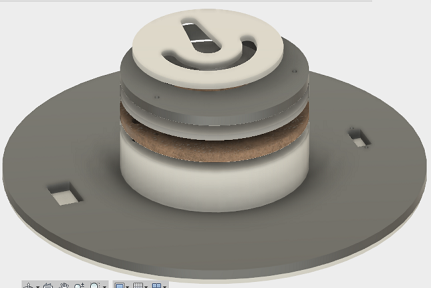
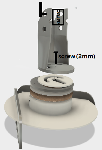
Originally I wanted to make one axis model, and designed this stand. Even after discarding that idea and first panel back, I kept this stand since it still works with the new panel back. For now, the lower circle and half circle (originally for wire) are not used.
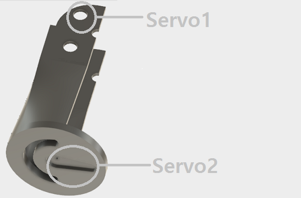
The bottom has an arc hole for the wires and dent for the servo arm. Small hole is for the screw that will connect the servo motor and the panel stand.
- (3D printing)
With the same setting (except that I chose no support), it came out fine.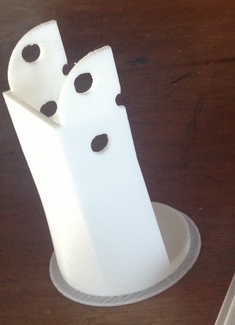
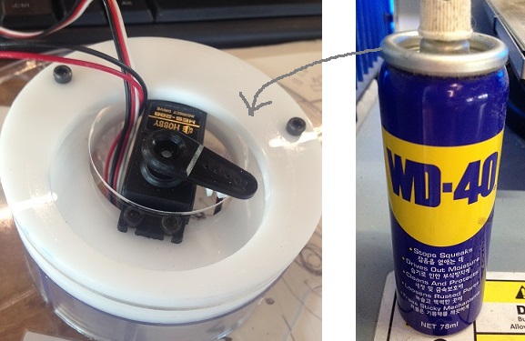
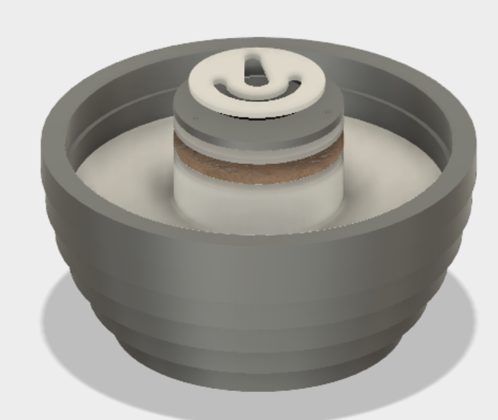
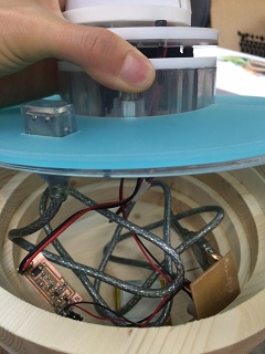
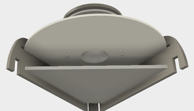
- The servo2 should rotate the whole body:stand with panel+panel back+panel case+servo1(+alpha). To hold the weight, and also to distribute the weight evenly, I used Edu's idea:
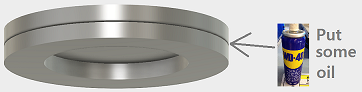
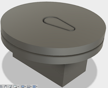
The bottom ring can hold the weight from the top disk where the servo arm is connected, and acryl+oil makes very smooth turn.
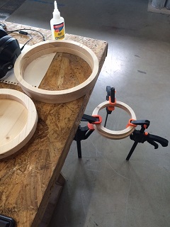
- (Laser cutting)
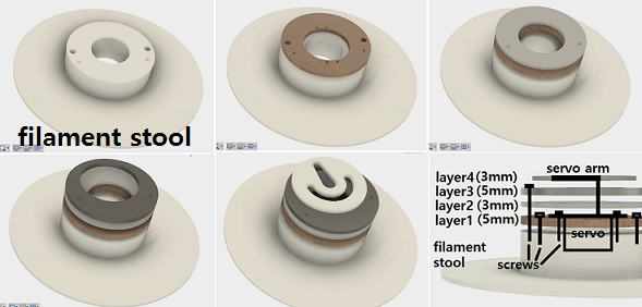
I used filament stool as a base to hold the servo2 and the above ring-disk system. 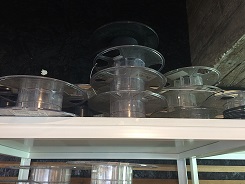 (they are strong enough, and we have bunch of them)
The layers look like this:
Note:
- Laser cutter setting: speed 4, power 95 for 5mm. (even for 3mm, it is okay to use the same setting)
- Screws and nuts: 4x3mm (servo), 2x6mm (up to layer 1), 2x3mm (up to layer 3)
- Apply oil between layer 3 and layer 4. Only for contacting area.
 (Apply oil on this layer 3)
- Arc hole is for the wires (back and forth).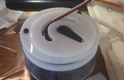
- Screw the servo arm at 90 degree.
- (CNC cutting)
The bottom of filament stool will sit on the third layer (from the top).
I cut 18mm plywood using 6mm 1F upcut with 16000 RPM, Feedrate=100
I also wanted to have acrylic cover for the filament stool for the switch and usb outlet.
- Extra: minimal base - I need some place only for lipo charging pcb with battery, and usb charging pcb, so made simple acrylic legs and plate(5mm) using laser cutter.)
 : Legs
 : Detachable plate

- Connect panel back and the stand

Note: screw the servo arm at 180 degree.
- Connect parts for the stand.
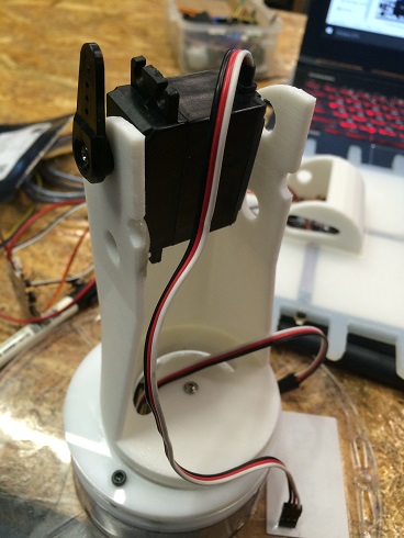
- Connect servo 1, 2, and four sensors to the main pcb. 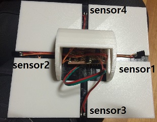
- Connect a switch to the wires for power supply of the main pcb so that, if needed, I can charge without tracking the sun. Connect the end of the wire to the lipo charging pcb.('MOTOR')
- Connect solar panel wires and lipo battery to the lipo charging pcb.('SUN', 'BAT', respectively.) For now, I ignored the white wire of the battery.
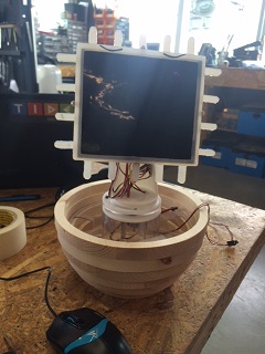
My first plan was to be green as much as possible since solar power is also green energy. For example, I wanted to recycle filament stools for the main body and the bottom, so designed just one axis model which can be tilted at the bottom (which is better than having tilted panel).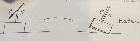
I actually tried to make it this way (even using cable zip ties) since it can make the model foldable (due to the looseness of zip ties), but, thanks to Rodrigo and Edu, I soon realized that this is not recycling class and discarded this idea, and decided to use two axis instead.
 (..In memory of the first model.. :)
Mistakes:
- flaws in code-ackward movement, stuck at the end,smoothing,..
- flaws in printing: too thick raft-impossible to remove.
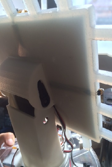
- flaws in design: hard to measure exactly how deep the hole for servo arm should be for the panel stand to fit in it.
Didn't have long enough screw to connect the servo arm and panel stand, so had to use glue gun.
I want to add networking function later: this(bridge) will send its rotation data to other flowers(nodes) or other devices with solar power panel, and they can also turn accordingly.
Update: after getting comment from Neil, I used cable zipties (+some double sided transparent tape) to fix the underneath wires.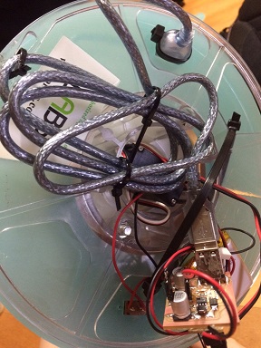 (I know. I don't care about the beauty that much. But I checked if all the connections are safe, and, yes, they are!)
- And I don't know where to insert these (from feedback), so I add them here:
1. What is the deadline? : June 14 (presentation day)
2. What tasks have been completed, and what tasks remain? How will I complete the remaining tasks? : (1) Completed : 2 axis tracking system which is well responsive to the light source, and lipo battery/USB charging systems. (2) I will mention further with the next questions. Briefly speaking here, I want to improve charging system. It is working fine, but not quite practical. (3) First, I plan to study more about solar power. I already began to take a course 'Solar power' at edX.org. Through this course and self-study, I want to get to know the kinds, the efficiency, etc. of the solar panels, and so I can pick a proper solar panel for my use, and then work on how to make more practical charging system.
3. What has worked? what hasn't? What questions still need to be resolved?: (1) Battery is charging well, and USB charging is also possible. But I realized that the current is low to charge my phone, so I just play music with this. (It can play my speaker) (2) The structure is not very good in terms of placing. If I take it out of the pot (for example, to deal with the wires), then it is hard to place it. The neck connecting panel stand and panel case is sturdy, but I don't want to give any pressure there, and the bottom has wires even after using zipties, so it cannot stand on them. I am thinking of making small space so that it can stand by itself even outside the pot.
4. What have you learned? : I studied many things about solar power charging system to make one for mine, and although it is just 5V for now, I think I can extend this to 12V. I just began to study. I also learned how to recycle wax, how to have smooth and strong rotational system. I knew nothing about servo+phototransistors, so that is also big fruit.
Download design files here (and fusion360 file here). PCB design files and arduino codes are given earlier.)
