#03week
3C - Computer-Controlled Cutting
tasks- - design something in 2D vector and get it processed on the vinyl cutter
- - design, make, and document a parametric press-fit construction kit
- - accounting for the laser cutter kerf, wich can be assembled in multiple ways
- - make laser cutter test parts / varying cutting settings and slot dimensions (characterizing)
individual
group
this weeks assignment is about cutting with computer controlled machines. There are certain machines that can cut through different materials. Just to name a few: vinyl cutter, laser cutter, a plasma cutter, water jet cutter, cnc machine with oscillating blade and I guess a few more.
But for this weeks task we will focus on vinyl cutter and laser cutter machines. Here at our FabLab in Kamp-Lintfort we have a small vinyl cutter from Silhouette for up to 8 inches wide and 10 feet long material and a bigger one from Summa the S2 D120 for 48 inches/ 120 cm wide materials. As they are both vinyl cutters the basic workflow is the same. The main differences are quality of the cuts, speed, capacity and material range. For the laser cutter we have access to an Epilog CO2 Fusion 60w laser cutter with a working area of ca. 100 x 70 cm / ca. 40 x 28 inches.
Vinyl cutters can only process vector data, because the definition of the path is needed for the blade to travel from a starting point to an endpoint. The same applies to the laser cutter if the material has to be cut, but with those machines also raster files can be processed for engraving jobs for example.
As described in the 2nd week assignment, there is a difference of quality between raster and vector. This difference plays a big role only for the laser cutters as for vinyl cutters those usually process only vector.
With a vinyl cutter we can cut certain materials not only vinyl, also paper, adhesives, copper. And this is now where the first tasks of this week gets into the game - I have to design something in 2D vector and to it with a vinyl cutter. I liked the idea of a notebook sticker - so i designed a sticker using Affinity designer.
Vinyl Cutter
- First I made up my mind
- Then I layout the design in Affinity, to do so I downloaded the original FabLab Logo as SVG to my computer. Then I separated the logo from the text and place the new text into it. I sized the text and aligned it to the logo as I thought it should be. After checking with the split-screen-view in Affinity - a very handy feature I must say - I prepared the export as an pdf/eps file for the vinyl cutter.
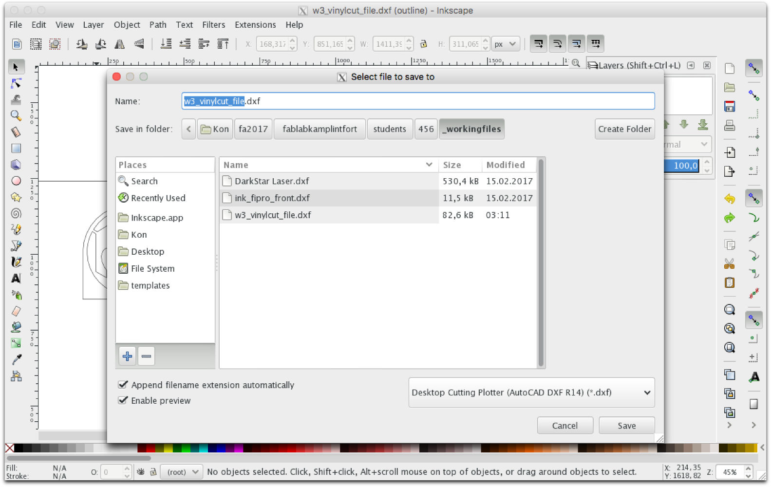
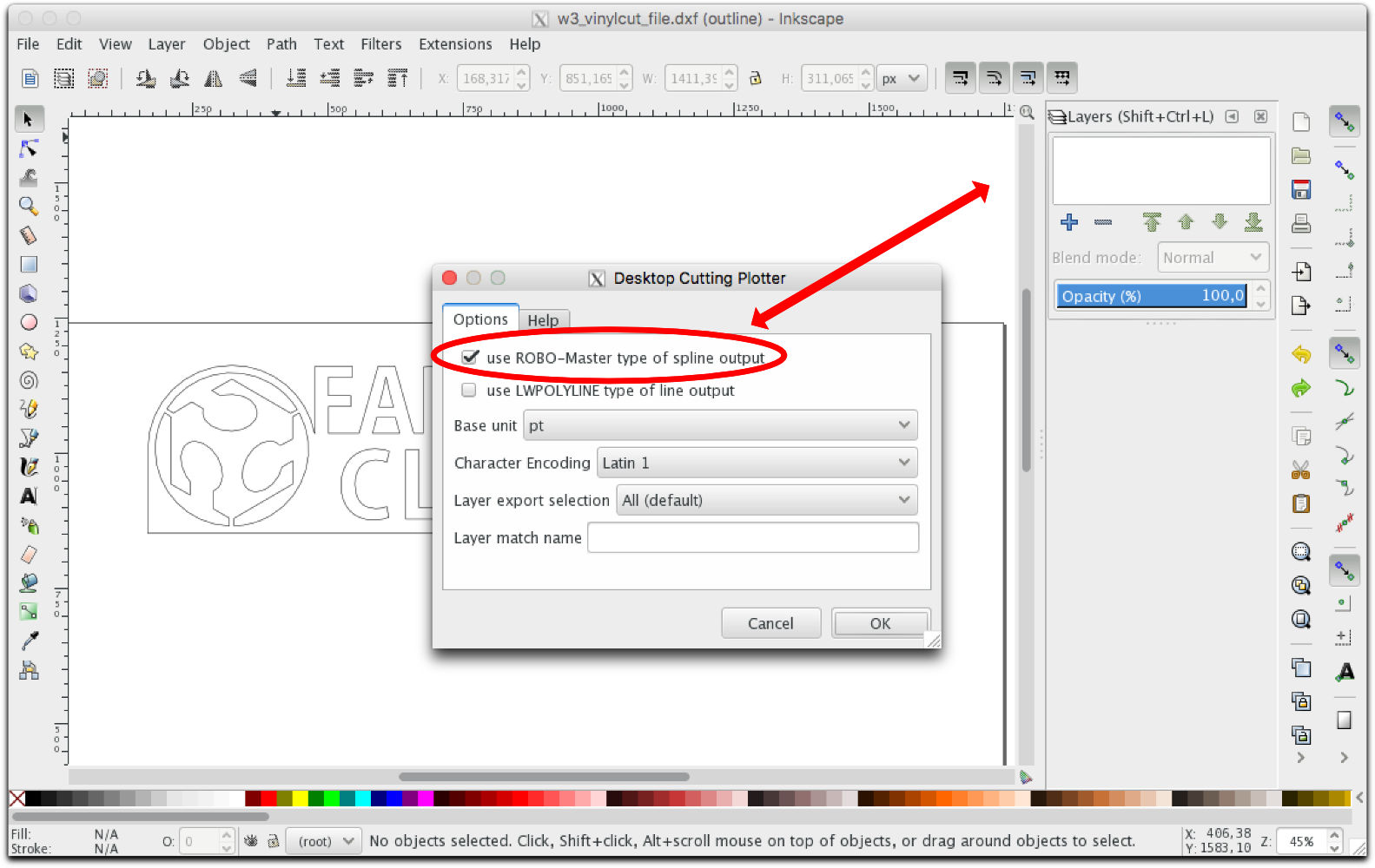
- Eventually exported the file as pdf/eps, but here I run into a problem. The Software for the Silhouette Cutter didn't support any PDF or eps for import. But this shouldn't be a problem, as Neil told us that there isn't just one tool/software for any task but a couple. So I loaded the ready made files into Inkscape and exported/safed them as dxf files (screen shots)
- Finally I loaded the file into the Cutters Software and after that I aligned a sheet of self adhesive vinyl in the cutter. I checked the position of the blade but as I was not the only one who had to cut vinyl the height of the blade was correct - so I started the job.
- After cutting I had to manually get rid of the material that I didn't need. For this I used a tweezers and mainly a sharp 60 degree blade cutter with those tools it was easy to clean up my sticker.
- Then I had to apply application tape to get the sticker of the backing and with a squeegee I applied firmly the sticker onto my notebook. I waited then for a minute to let it adhere on the surface properly and the I removed the application paper gently by pulling it by a very flat angle. Always watching not to tear a tiny part of it by mistake.
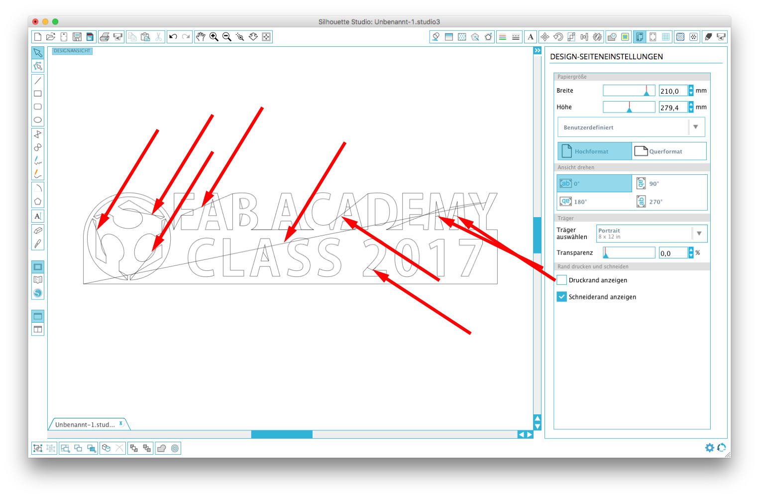
But than the next weird thing happend - the file looked akward after opening it in the cutter application. It had paths through the objects where it shouldn't have any...

Laser Cutter
To work with a laser cutter we have to follow some safety rules. Because a laser cutter works with power and heat and unvisible light an operater should always be by the machine during cutting. "A laser is not a teleporter" Prof. Neil Gershland said to us. Meaning that all material what gets in contact with the laser doesn't just disappear - no - it burns, it evaporates, it just takes tiny bits of the processed material which then is in the air all over the place.Therefore a very important addon to the laser cutter is the ventilation box that keeps sucking all the air from inside the box through a filter section to the outside.
After a brief introduction to the Epilog Laser I had to make a sample. So I created first a circle in Rhino, than I added a eight-pointed star smaller than the circle. I aligned them both verticaly and horizontaly. My next step then was to create an polar array of 8 smaller circles at the edge of the main circle.
Rhino has a function that gives me the possibility to trim curves and lines that are somehow intersecting with other geometries and after the trimming I connected the lines that were touching eachother to a close curve again. So I created an curve object consisting of 2 closed curves.
As a final preparation for the laser cutter, I assigned a different color to each curve so that they can easily be differentiated. Also this is neccessary for some important settings within the Laser cutter.
Especially the setting section of the Laser cutter is a very important part - the right or the wrong settings decide over success or failure. - For each material that can be used in the laser the settigns have to set up in the manner of the job. Cutting or engraving or maybe both - than also the order of the actions is important for the timing. Sensitive materials need to be setup very präzise and carefully to avoid any damage to them. Sometimes it is better to do a job in two or more runs.>br> At least the settings for Power, Speed & Frequency have to be setup. Below there is a table where some factory settings are listed and these are a good point to orient and to find own maybe better settings based on them.
Here some basic information about the Raster Mode: the RM is used for engraving or marking materials. Typical uses include engraving clipart, scanned images, photos, text and graphic images.
Of course Vector lines too can be engraved rather than cut, but then the line thickness should be set 0.006” (0.152 mm) or greater.
Vector Mode: this should be selected when only cut lines are prepared or for use with the Red Dot Pointer for previewing the job processing area. In this Mode a line is only recognized as a line to be cut based on the line width (or stroke). Important!!! These lines can also be affected by resolution. Please test before you start the whole job or look in the manual of the laser cutter. To make things easy, set any cut lines to a line width of 0.001”, or hairline width in your illustration/vector app.
Combined Mode: Used when both modi - engraving and cutting have to be processed within the same job. The laser will always engrave first, and when this is daone it will continue with the cutting in vector modus.
As an extra task I set up a lettering and prepared it to be engraved not cut in the laser. To achieve this I had to convert the curves from the letters with the |hatch| command and their own color.
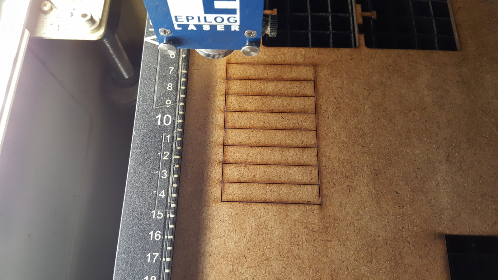
In the Laser preferences I had to adjust a view settings to my needs to get the job done, like job type, piece size, resolution and of course the settings for raster and vector job types. And in the tab 'color mapping' I had the possibility to make individual settings and assign thme to each object with corresponding color. Now for the Kerf test I designed a simple object within Rhino just a square with the measurement 50 x 80 mm and some cross sections of 10mm distnace each. I laser cut them in 3mm MDF for measurement....
...and the result...
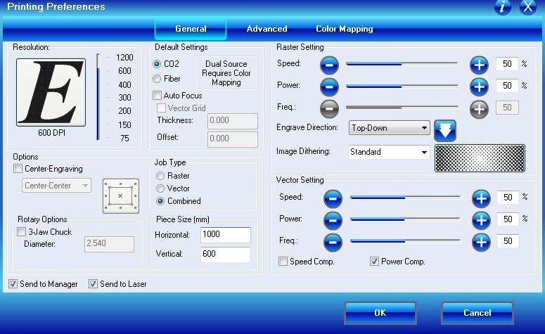
Laser settings...
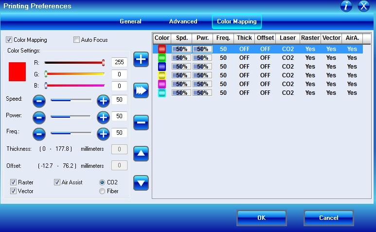
..the settings for colormapping
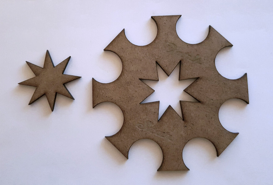
my first laser cut..
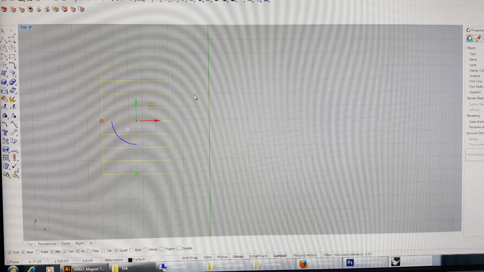
designing a simple reference object in Rhino to test the laser
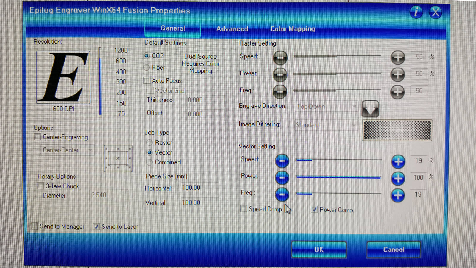
these are the settings I used
nothing spectacular.
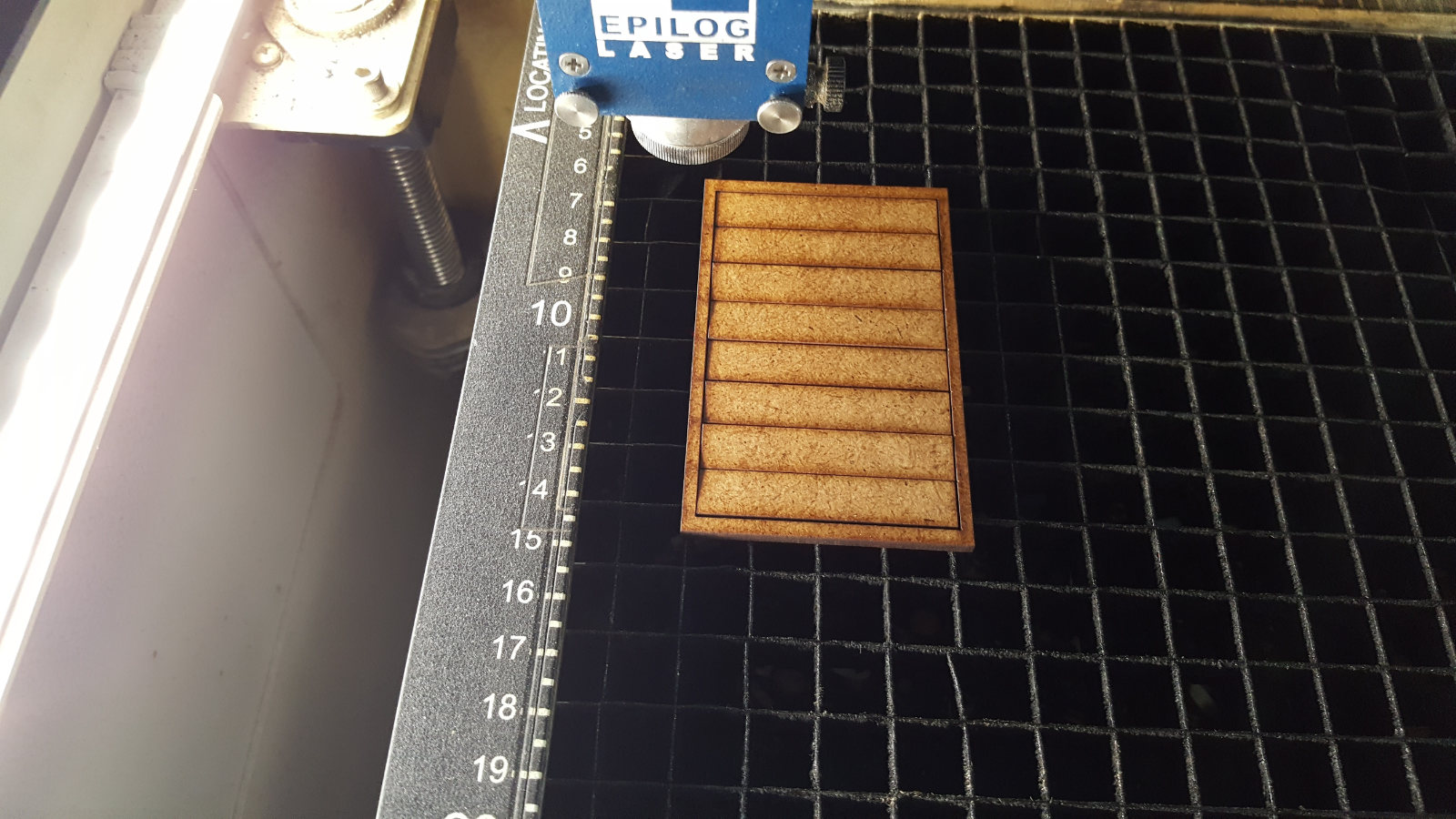
really a clean cut..
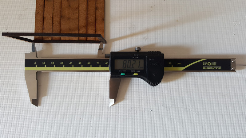
I measured the total width of the cut out and the inner frame
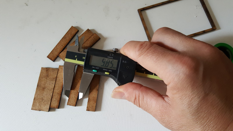
...also the single stripes just to check the sizes,
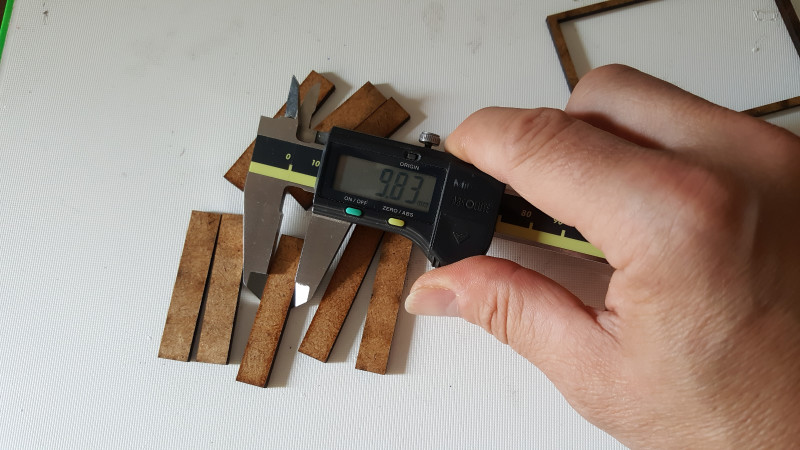
...as assumed they differ sligthly
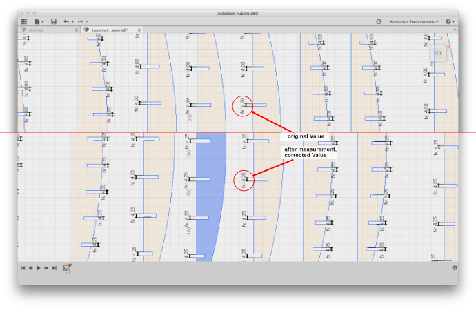
Then I measured the inner distance from the frame and the total distance of the the cut outs, see following image
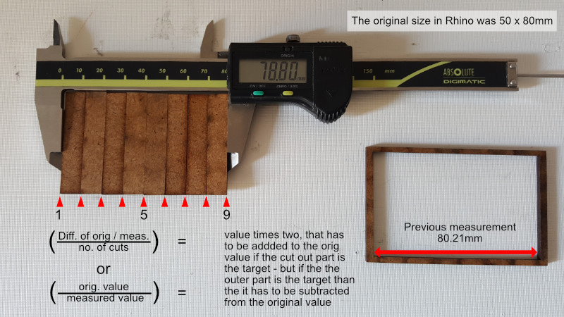
Then I divided the difference from the measured & original length by the numbers of cuts...this is the value I had to add or subtract in total
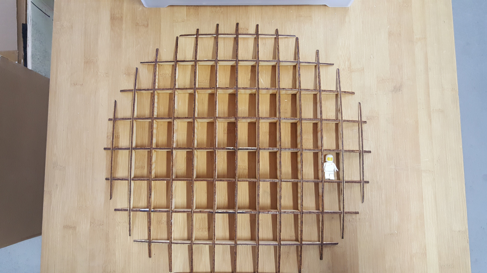
For the second task in this weeks assignment, I designed a pressfit board system for my son's lego figure collection. The shape is a somehow round - elipsoid form and for having it open for different materials and thickness the slots have to be parametric so that it can be changed in a "second" to be ready for processing. In Rhino the plugin 'Grasshopper' has to be used - it's a powerful and full featured plugin and can extended even more by adding other corresponding extensions/plugins.
But for this time I used Fusion 360, fot it is a quite simple design and structure. To make someting in Fusion parametric the specific value has to be defined as a variable before in the 'Change parameters' option.
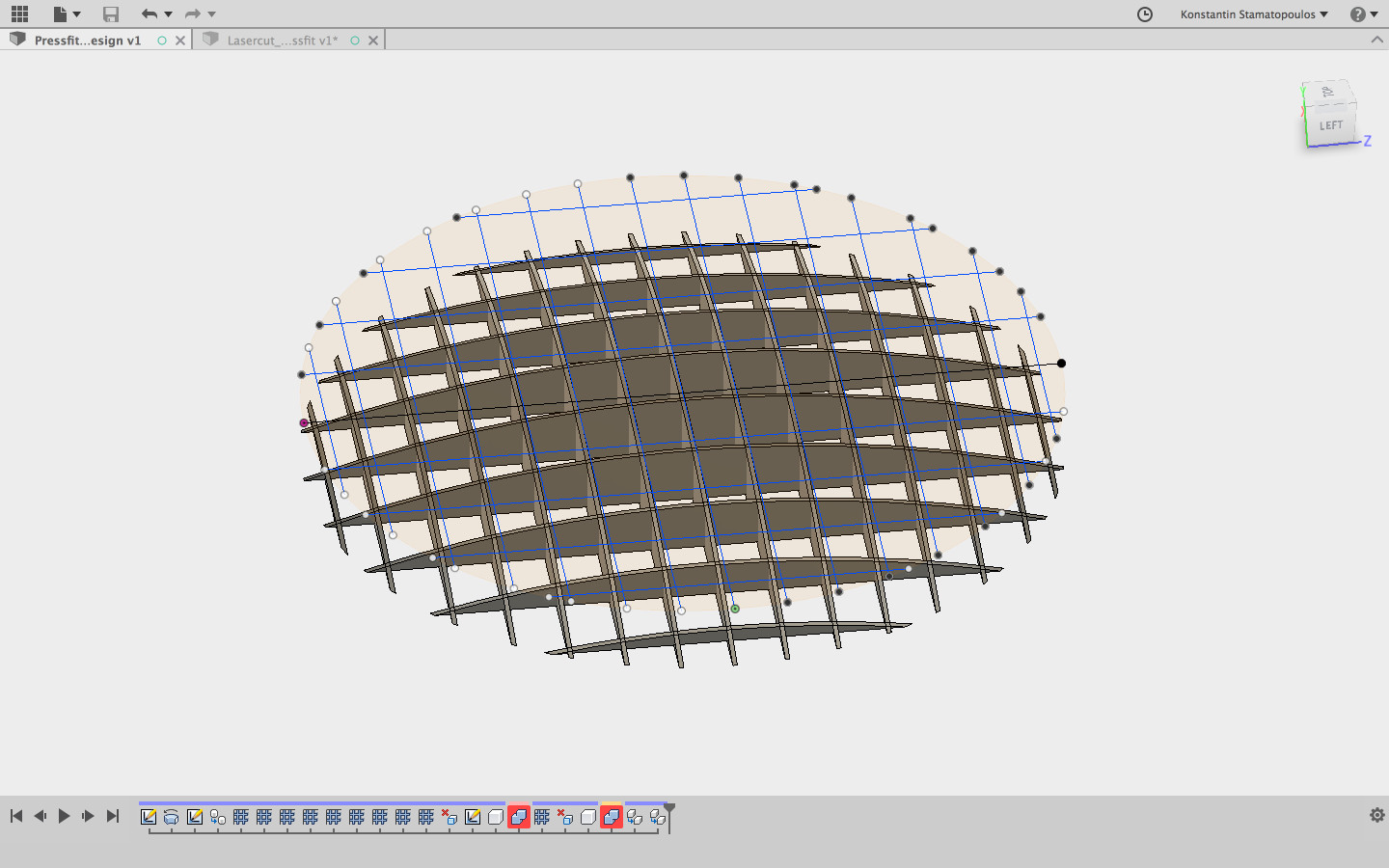
the CAD design for the pressfit assignment
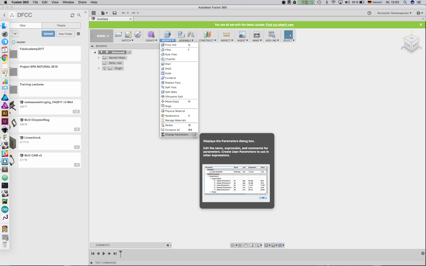
...in this option box the parameters/ variables have to be defined for parametric usage

Also in the same box, changes to the values can or have to be made..
It can take some time for the changes to take action, depending on complexity an amount of variables that have to recalculated
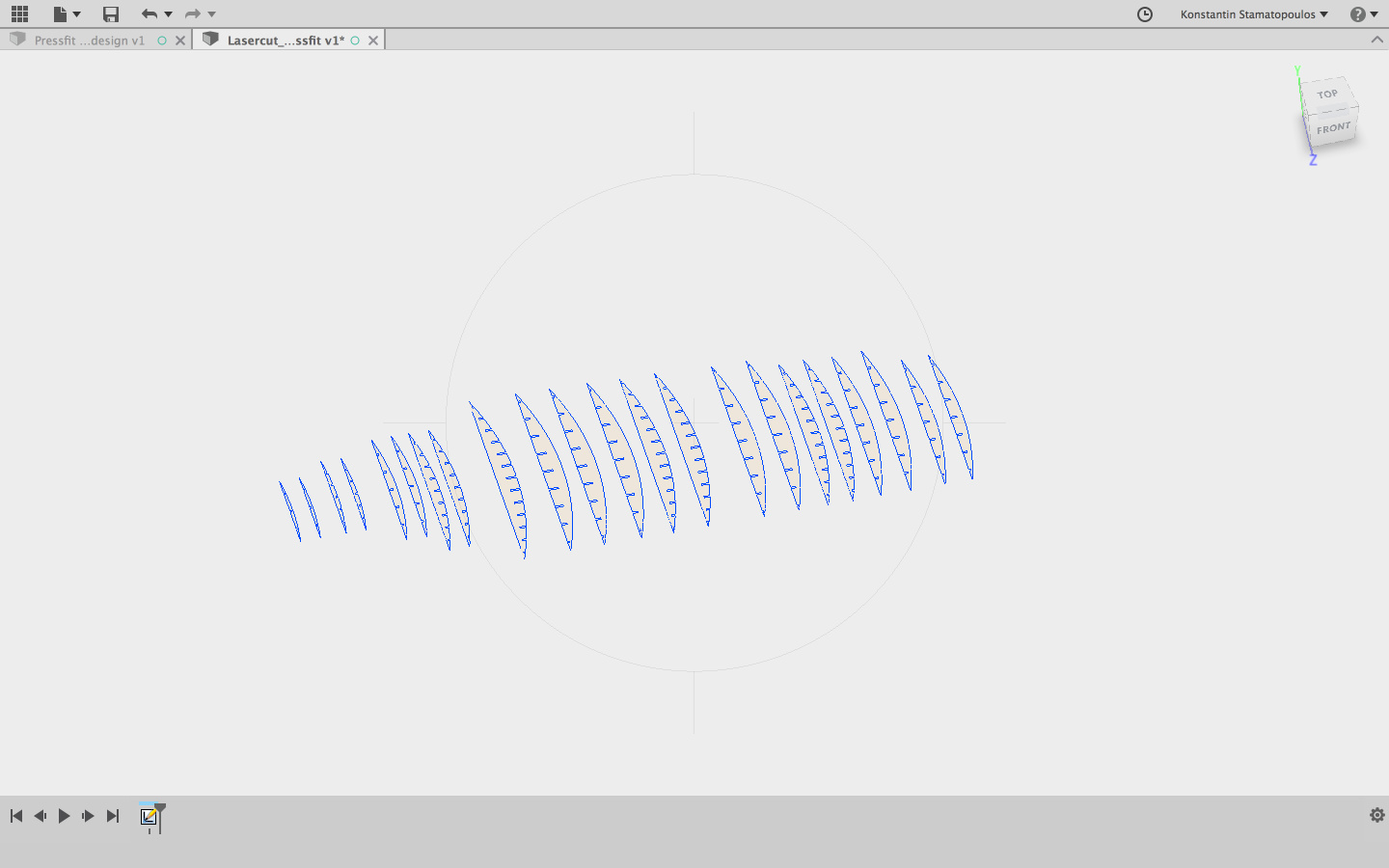
...the single parts are layout flat ready for the laser cutter,
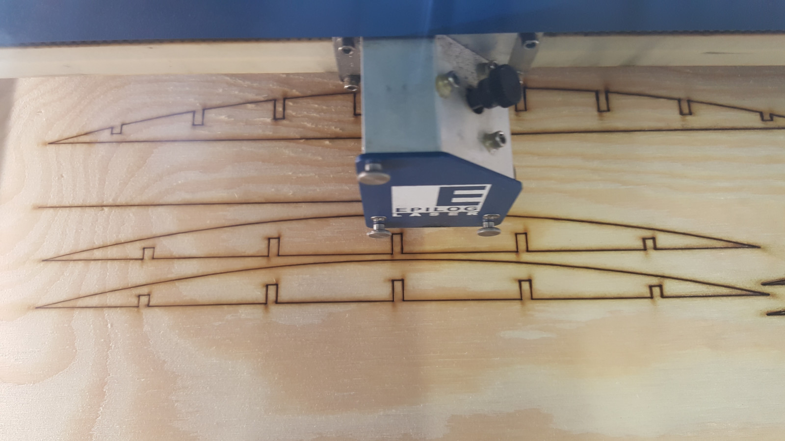
...after all changes are done, its time for the laser cutter
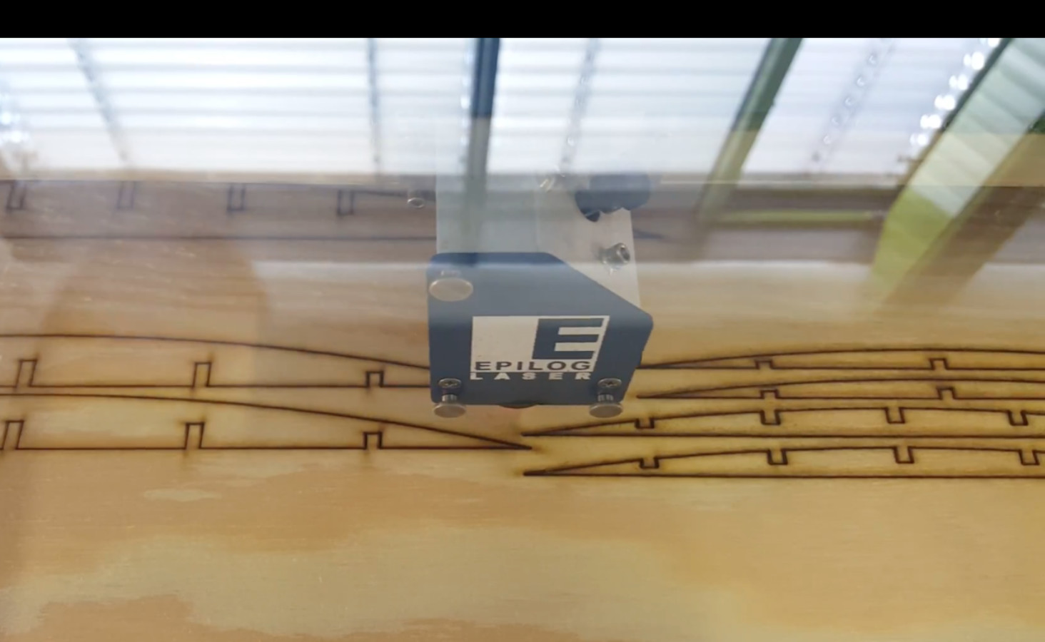
...unfortunately the sheet of wood wasn't totally flat - so I had to go for a second run
But it worked out just fine and the first habitant already jumped in..
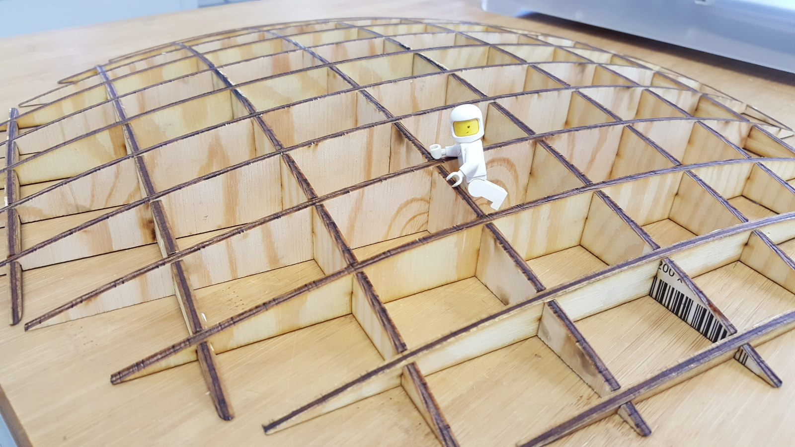
Heroshot
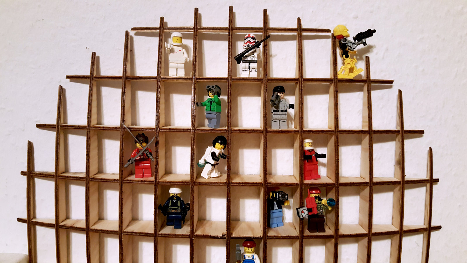
Heroshot
Basic recommended settings by Epilog
Settings (CO2) Material DPI/Freq. 	30 watt    40 watt    50 watt    60 watt    75 watt    120 watt
Acrylic
Photo Engraving		300 DPI		90s 60p	    90s  55p   90s 50p	 90s  45p   90s 40p   90s 30p
Text/Clipart Engraving 	300 DPI		90s 80p     90s  75p   90s 70p   90s  65p   90s 60p   90s 55p
Text/Clipart Engraving 	600 DPI		90s 75p     90s   70p  90s 65p   90s  60p   90s 55p   90s 50p
Cutting 1/8” (3 mm) 	100 f		5s 100p     6s  100p   7s 100p    8s 100p   10s 100p  12s 100p
Cutting 1/4” (6 mm) 	100 f		2s*100p     3s* 100p   1s 100p    2s 100p    3s 100p   7s 100p
Cutting 3/8” (9.5 mm) 	100 f		2s*100p     3s* 100p   1s 100p    3s 100p
Cutting 1/2” (13 mm) 	100 f		1s 100p

Alumamark
Engraving               300 DPI		90s 55p     90s 45p   90s 35p     90s 25p   90s 20p    90s 15p
Engraving               600 DPI		90s 45p     90s 35p   90s 25p     90s 15p   90s 10p    90s 5p

Anodized Aluminum
Photos/Clipart          400 DPI		90s 55p     90s 50p   90s 45p     90s 40p   90s 35p    90s 30p
Photos/Clipart          600 DPI		90s 50p     90s 45p   90s 40p     90s 35p   90s 30p    90s 25p
Text                    600 DPI		90s 60p     90s 55p   90s 50p     90s 45p   90s 40p    90s 35p

Cork
Engraving               300 DPI		90s 50p     90s 45p   90s 40p     90s 35p   90s 30p    90s 25p

Fleece
Engraving               150 DPI		90s 35p     90s 30p   90s 25p     90s 20p   90s 15p    90s 10p

Glass
Engraving               300 DPI		15s 100p    20s 100p  25s 100p    30s 100p  35s 100p   40s 100p
Leather
Photo Engraving         300 DPI		90s 40p     90s 35p   90s 30p     90s 25p   90s 20p    90s 15p
Text/Clipart Engraving  600 DPI		90s 45p     90s 40p   90s 35p     90s 30p   90s 25p    90s 20p
Cutting 1/8” (3 mm)      50 f		50s 100p    45s 100p  40s 100p    35s 100p  30s 100p   25s 100p

Mat Board
Cutting                  50 f		20s 60p     20s 50p   25s 40p     25s 30p   30s 40p    30s 30p

Marble
Photo Engraving         300 DPI		90s 55p     90s 50p   90s 45p     90s 40p   90s 35p    90s 25p
Text Engraving          600 DPI		90s 65p     90s 60p   90s 55p     90s 50p   90s 45p    90s 35p
Every marble is very different for settings. Start low and increase the
power with a second run if you haven’t used that marble before.

Painted Brass
Engraving               300 DPI 	90s 45p	     0s 40p   90s 35p	  90s 30p   90s 25p    90s 15p
Engraving 		600 DPI 	90s 40p     90s 35    90s 30p     90s 25p   90s 15p    90s 10p

Plastics
Engraving		300 DPI	        90s 40p    90s 35p    90s 30p     90s 25p   90s 20p    90s 15p
These settings work well with many plastics, including plastic phones
and covers. Even one color plastics can achieve a great look when engraved.

Plastic (2 Layer Laser Engraveable)
Engraving		300 DPI 	90s 80p	   90s 75p    90s 70p     90s 65p   90s 40p    90s 35p
Engraving		600 DPI 	90s 75p    90s 65p    90s 50p     90s 35p   90s 25p    90s 20p
Cutting 1/16” (1.5 mm)   100 f		10s 85p    10s 75p    10s 65p     10s 55p   10s 40p    20s 40p

Rubber Stamps
Engraving		600 DPI 	15s 100p   20s 100p   30s 100p    40s 100p  60s 100p   80s 100p
Cutting			100 f 		5s 100p    10s 100p   15s 100p    20s 100p  25s 100p   30s 100p

Stainless Steel w/Cermark
Engraving		600 DPI 	20s 100p   25s 100p   30s 100p    35s 100p  45s 100p   55s 100p
Twill
Cutting			25 f		50s 40p    50s 35p    70s 100p    90s 100p  90s 80p    90s 60p
Wood
Photo Engraving	 	600 DPI 	30s 100p   40s 100p   50s 100p    60s 100p  70s 100p  100s 100p
Clipart/Text Engraving	300 DPI 	20s 100p   30s 100p   40s 100p    50s 100p  60s 100p   90s 100p
Clipart/Text Engraving 	600 DPI 	25s 100p   35s 100p   45s 100p    55s 100p  65s 100p   85s 100p
Deep Engraving		600 DPI 	5s 100p    10s 100p   20s 100p    25s 100p  30s 100p   60s 100p

Thin Veneer
(Cutting) 		  10 f		30s 100p   30s  80p   40s 100p    40s 90p   50s 80p    50s 60p
Cutting 1/8” (3 mm) 	  10 f	  	 3s 100p   6s  100p    8s 100p    10s 100p  20s 100p   40s 100p
Cutting 1/4” (6 mm) 	  10 f	 	3s* 100p   1s  100p    2s 100p     3s 100p   5s 100p   12s 100p
Cutting 3/8” (9.5 mm) 	  10 f		2s* 100p   3s* 100p    1s 100p     8s 100p
Cutting 1/2” (12 mm)	  10 f		 3s 100p
Downloads

This work is licensed under a
Creative Commons
Attribution-NonCommercial-ShareAlike 4.0 International License.