Mechanical and Machine Design
Intoduction
For the Machine Building, our team made a Solar Drawing Machine. This system is composed of two sub-systems:
I was responsible for the development and functionality of the solar tracker. In order for the solar tracker to be made, an appropriate structure (functional requirements) was needed, an appropriate PCB board and of course a program so that it can run on.
Functional Requirements
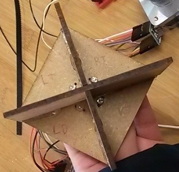
In order for the LDRs to be connected and work properly, they have to receive the same amount of sunlight, no less no more. To achieve that, something that would be able to give the system that ability had to be designed. So, a structure that when the sun is not perfectly perpendicular to the LDRs would give a shadow to them as a result of getting less sunlight and making them adjusting accordingly was designed and laser cut using a 3mm MDF. Two of the parts of the design were designed to work as a press fit and then were super glued to the base of the design were slots for the placement of the LDRs were also put.
The base was designed with little holes near the centre point of it so that they would easily get shadow when the LDRs are placed there. The vertical part of the design was measured to fit in the diagonal area of the base. The functionality of the vertical parts of this design is to make shadow to the LDRs when sun is not perfectly perpendicular on them.
Below you can see the design of the structure and the result after the laser cutting. For the laser cutting, I used the vector settings without the color mapping this time using only the "General" options as I have only cuts to do without any engravings. I used the settings of the machine for the 3mm MDF which are frequency: 30%, power: 100 and speed: 9%. More info for the laser cutter can be found on the "Computer Controlled Cutting" week.
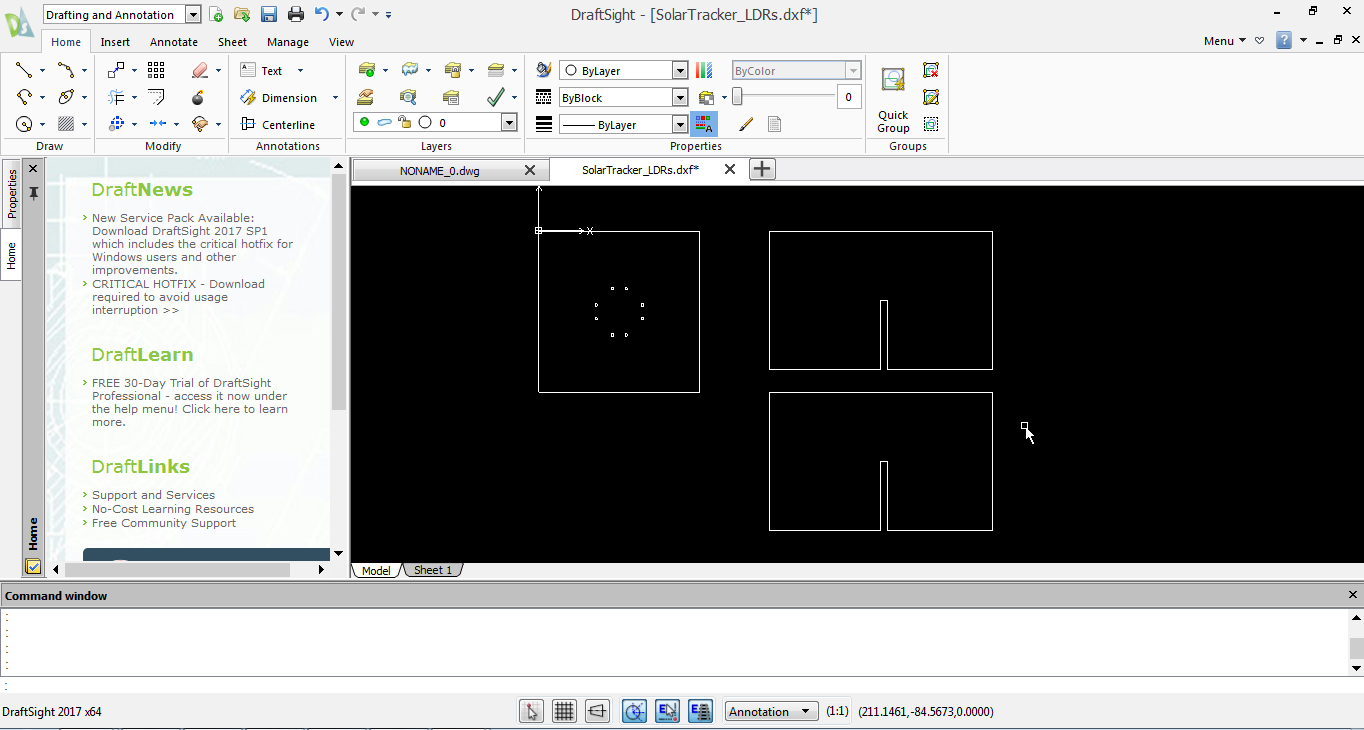
For software purposes I named the LDRs according to their positions as top left and right, and bottom left and right. This configuration helps for the programming of the solar tracker and the connections of the LDRs to the PCB board.
PCB Design
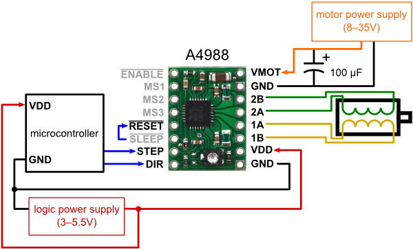
The solar tracker needed a PCB in order to be working. After some research on the internet, I found out the connections of the LDRs and the stepper motors. The stepper motor needs a driver in order to be working. The driver used was the A4988 Pololu Stepper Driver. As two stepper motors were needed for the system to work, one to control the horizontal movement and one the vertical, I used two drivers.
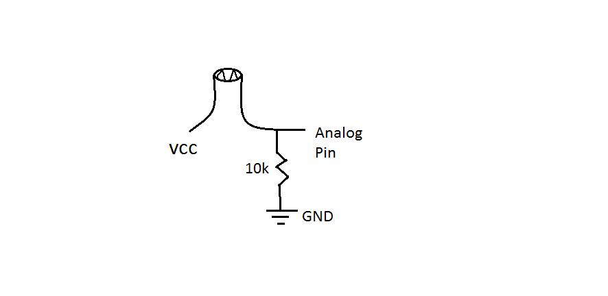
Below, the connections of one LDR and one stepper driver are illustrated.
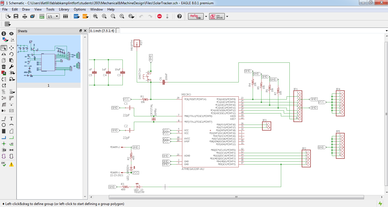
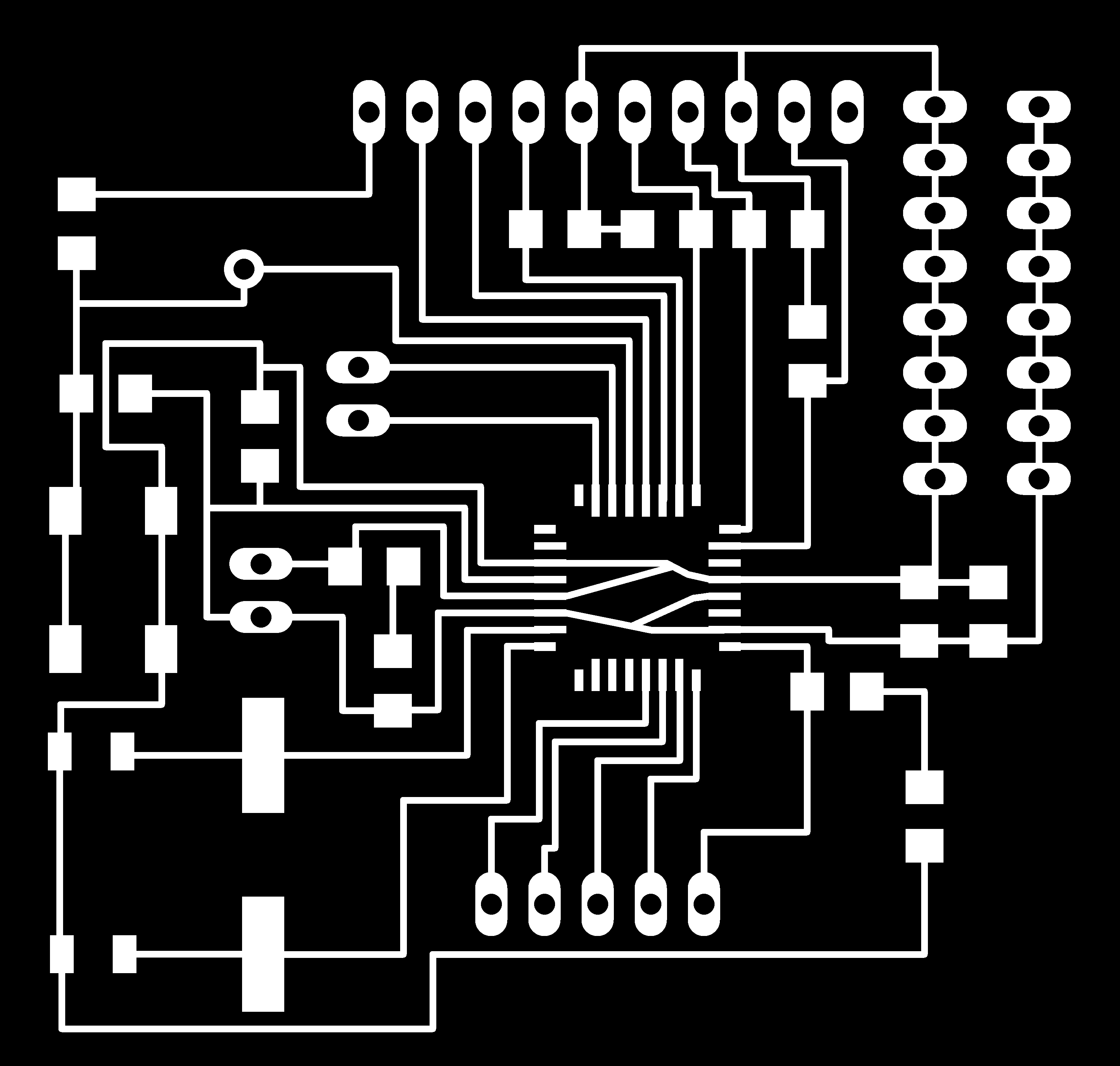
Taken the above connections into consideration, I modified the satshakit made by Daniele Ingrassia into the requirements of my system. After making the eagle file, I proceeded on milling using the same method as the "Electronics Design" week. The settings for the internal path and external path respectively are given below:
Below, you can see the eagle file of the PCB Board:
Software of the Solar Tracker
For the software of the system, I followed an example code I found on Instructables. I modified it quite a while using the stepper.h library insted of the servo motors. I still used the same mathematical for the measuring and comparison of the sunlight. Many example codes of the solar tracker systems use the same mathematical formulas, so I thought I will also give it a shot.
I wrote the code in Arduino language. For the programming of the board, I initially used the arduino board to upload the bootloader on my board and then I directly programmed my board using the FTDI-5V cable. In order to do that, the same procedure was followed as the "Output Devices" week.
The code can be found below:
#include < Stepper.h >

#define motorstep 100

//horizontal stepper
#define hstep 13
#define hdir 12
int step_hdivision = 10;
Stepper stepperh(motorstep, hstep, hdir);

//vertical stepper
#define vstep 10
#define vdir 9
int step_vdivision = 10;
Stepper stepperv(motorstep, vstep, vdir);

int ldrLT = A0; // LDR Left Top
int ldrRT = A1; // LDR Right Top
int ldrLD = A2; // LDR Left Down
int ldrRD = A3; // LDR Right Down

void setup(){
  Serial.begin(9600);
  stepperh.setSpeed(200);
  stepperv.setSpeed(40);
  }

void loop(){
  int lt = analogRead(ldrLT);
  //Serial.println (lt);
  int rt = analogRead(ldrRT);
  //Serial.println (rt);
  int ld = analogRead(ldrLD);
  //Serial.println (ld);
  int rd = analogRead(ldrRD);
  //Serial.println (rd);

  int dtime = 1;
  int tol = 50;

  int avt = (lt + rt)/2; // average value top
  int avd = (ld + rd)/2; // average value down
  int avl = (lt + ld)/2; // average value left
  int avr = (rt + rd)/2; // average value right

  int dvert = avt - avd; // difference of up and down
  int dhoriz = avl - avr; //difference of left and right

  // horizontal stepper motor
  if(-1*tol > dhoriz || dhoriz > tol){
    if(avl > avr){
      stepperh.step(step_hdivision);
      delay(10);
      }
    else if(avl < avr){
      stepperh.step(-step_hdivision);
      delay(10);
      }
    else{
      stepperh.step(0);
      delay(10);
      }
    }

  // vertical servo motor
  if(-1*tol > dvert || dvert > tol){
    if (avt > avd){
      stepperv.step(step_vdivision);
      delay(10);
      }
    else if (avt < avd){
      stepperv.step(-step_vdivision);
      delay(10);
      }
    else if (avl == avr){
      //nothing
      }
    }

  delay(dtime);
  }
Although the above program is written for stepper motors, I tested it in the beginning by using servo motors. It seems by the first tests that the system is working:
Embedded in the whole system
So, after the first tests were done using the servo motors, more successful tests were run with the stepper motors again successful as it appeared to be. So, it was time to embed it in the whole system and see if it actually works.
The LDRs were embedded on the lens using double scotch tape so that the lens moves according to the sun as desired. The two stepper motors were embedded on the appropriate places that my colleagues designed for that specific purpose.
Below, the testing of the solar tracker is made. It seems to be a bit slow on the movement but it works. :)
Downloads
LDR Structure.dxf | Solar Tracker.ino | Solar Tracker.sch | Internal Path of solar tracker PCB.png | External Path of solar tracker PCB.png