Embedded Programming
Intoduction
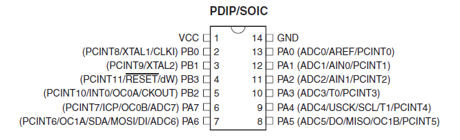
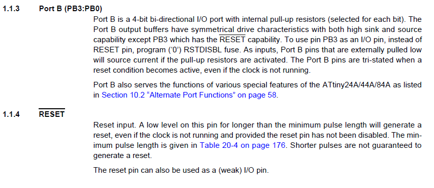
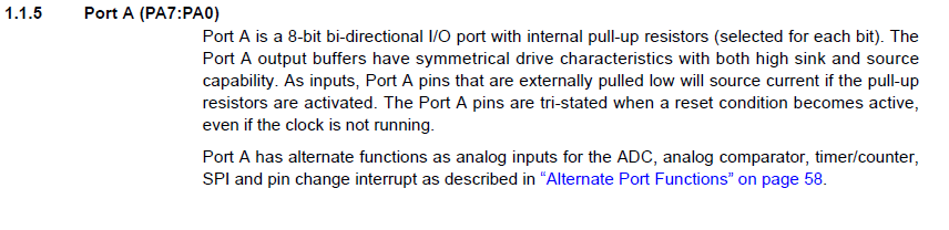
Before starting to program I had to read the datasheet of the microcontroller again in order to understand better the usage of the pins so that I can program the board. From reading the datasheet, I learnt that there are three different kinds of ports. There are DDRx for the Data Direction Register, PINx for the Pin Input Register, and PORTx for Pin Output Register. Also, every port works differently.

Programming
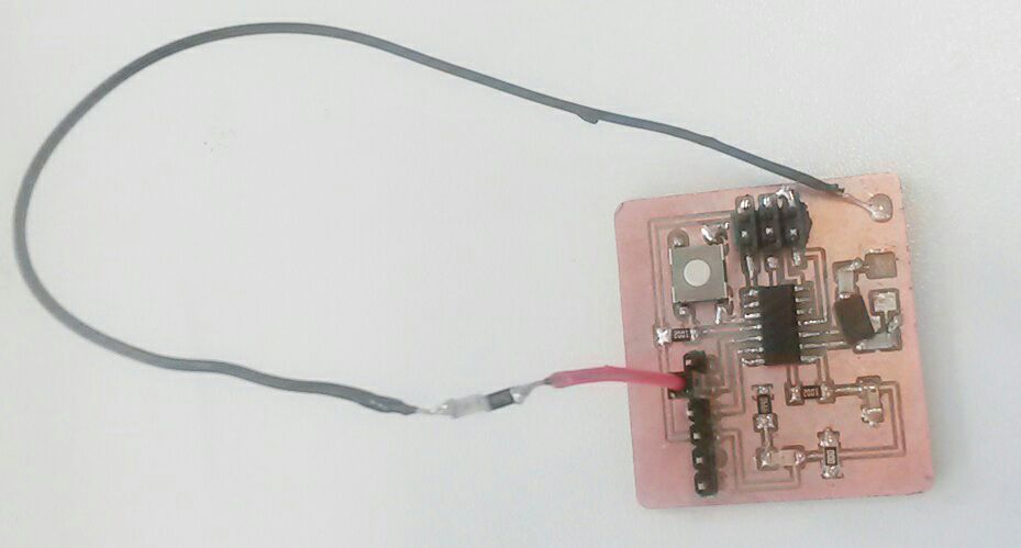
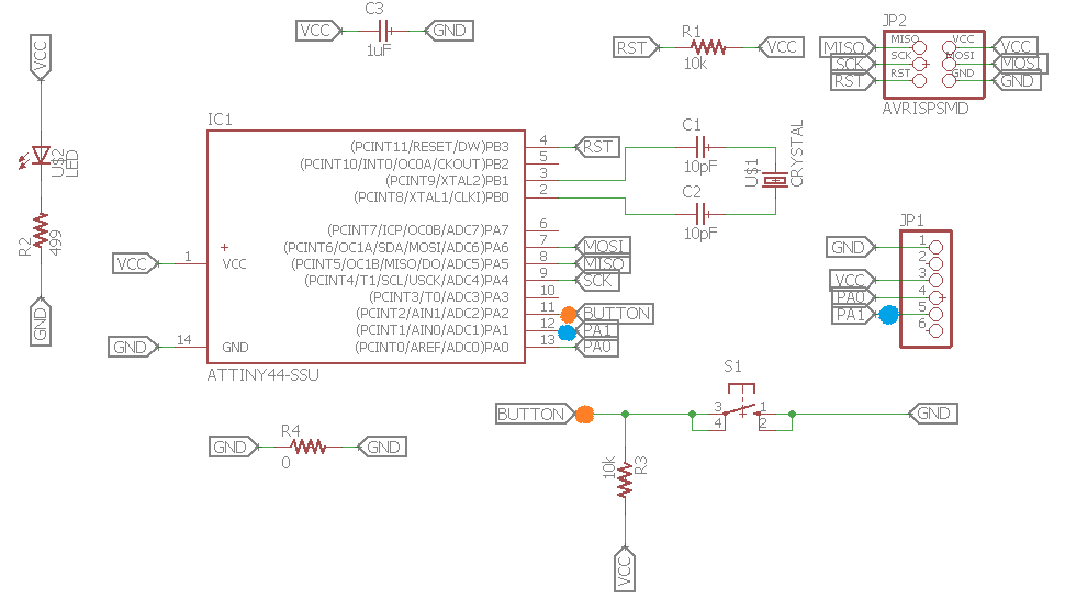
After reading the definitions of the PORTs and pins and understanding how to use them, I used the pinouts of my microcontroller to control an external LED. As the previous week, I only embedded an LED for the indication of the power on my board, I had to add an external LED in order for me to be able to control it. I added the LED by connecting one side of it to the GND and the other end to a 499 Ohm resistor and to a digital pin of the microcontroller.
After adding the external LED, I was ready to program my board. For the programming I used the digital pin PA1 for the LED and PA2 for the button.
I tried the Arduino language and C. For the Arduino language I used the blink code by searching for the corresponding pin of the ATtiny to Arduino. PA1 in Arduino corresponds to the digital pin 1, so that pin was used for the Arduino programming. In C I used both the button and the LED. I programmed it so that every time I would press the button, the LED would turn on in case it was turned off and vice versa.
Below, you can find the program of C:
/* Test code in C language for Fab Academy */ // including pinout library and delay library #include#include //defining the frequency of the external clock #define F_CPU 20000000UL //main program will be executed here int main(void){ //set the LED DDR to output //PA2 => button pin //PA1 => led pin // 0 is input whereas 1 is output DDRA = 0b00000010; // entering on a loop while(1) /*bit_is_clear tests whether bit bit in IO register sfr is clear. This will return non-zero if the bit is clear, and 0 if the bit is set. */ if (bit_is_clear(PINA, PA2)){ _delay_ms(5); if (bit_is_clear(PINA, PA2)) switchLED(); } } //this function will be called to the main program void switchLED(){ if(PORTA == 0b00000010){ //if the led is on PORTA = 0b00000000; //switch the led off }else if(PORTA == 0b00000000){ //if the led is off PORTA = 0b00000010; //switch the led on } }
Here, you can find the Arduino program:
/*Program in Arduino language */

//declaring the pin where the LED is connected
LED = 1;

// the setup function runs once when you press reset or power the board
void setup() {
  // initialize digital pin LED as an output.
  pinMode(LED, OUTPUT);
}

// the loop function runs over and over again forever
void loop() {
  digitalWrite(LED, HIGH);   // turn the LED on (HIGH is the voltage level)
  delay(1000);                       // wait for a second
  digitalWrite(LED, LOW);    // turn the LED off by making the voltage LOW
  delay(1000);                       // wait for a second
}
For the compiling of both programs, I used the Arduino IDE. For the programming of the board, I followed the steps mentioned on the "Electronics Production" week. So, I was using Arduino as a programmer. Again, a mistake I almost did multiple times was to upload the program using the GUI symbol BUT the program should be uploaded using "Upload using Programmer" under the Sketch option.
Here is the Arduino Blink:
And here is the result of the C programming: