Electronics Production
Production of the Board
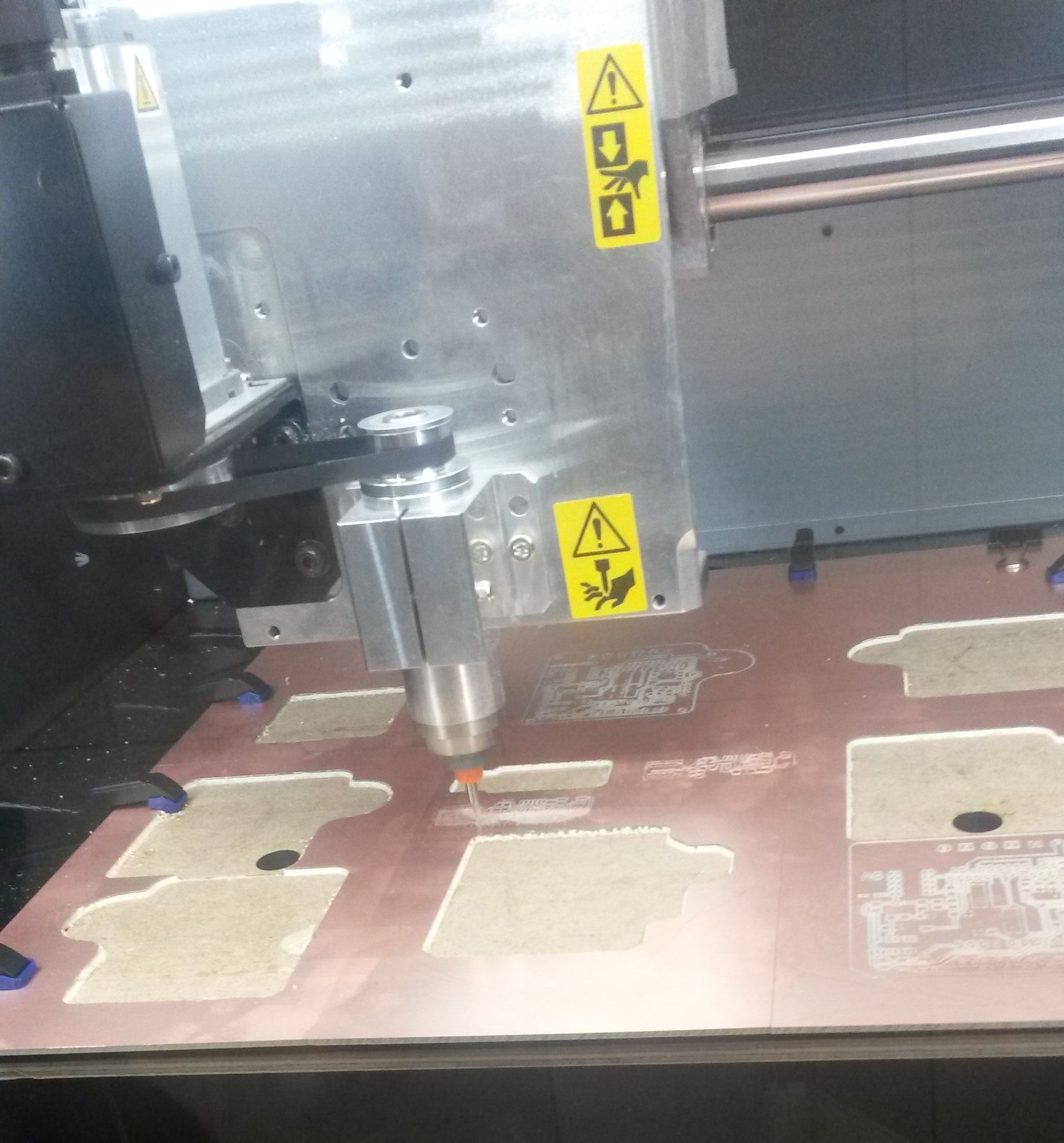
I produced the board with the Rolland milling machine. In order to do that we had to have two files. The one for the internal path of the PCB and the other one for the external. Luckily, those two files were given so all I had to do is use directly the machine.
During the process of production, I faced some problems between the connection of the computer and the machine and the machine itself. So, when the machine was getting stuck and connection between the computer and the machine was fine I had to do the following:
If problems between the connection occured all I had to do was to open the fabmoduleshtml5 (can be found on Dolphin > installed) and type in the command line sudo npm start
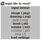
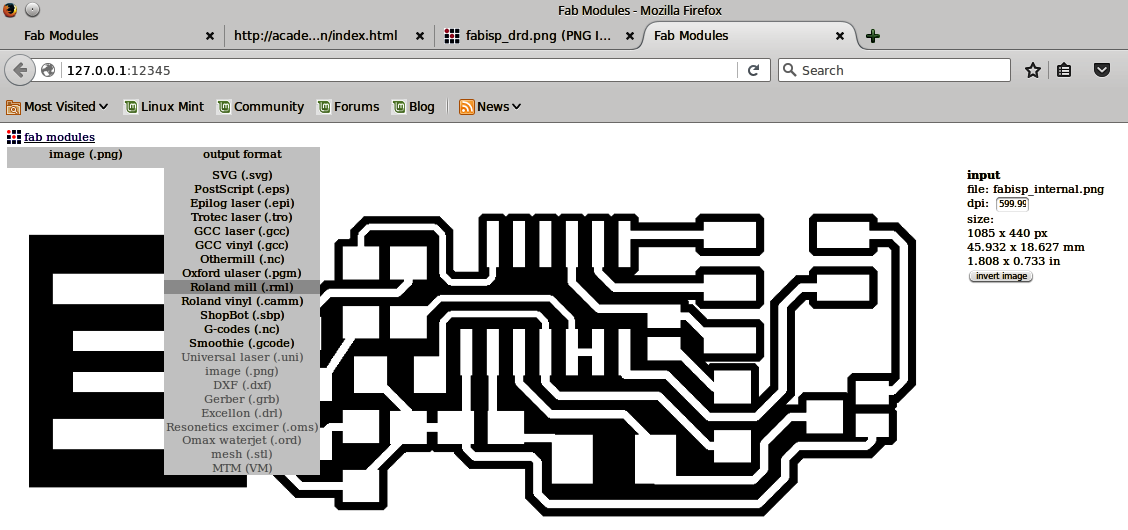
After having those in mind, we enter Fabmodules so that we can start the procedure of making the board. First, I made the internal path and then procceeded to make the external one. For the internal path I followed these steps:
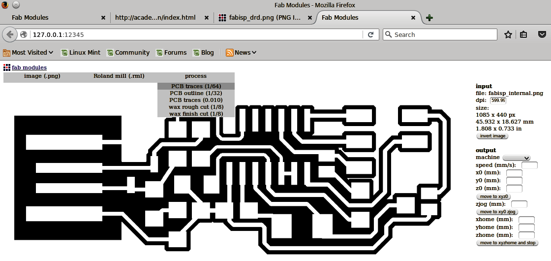
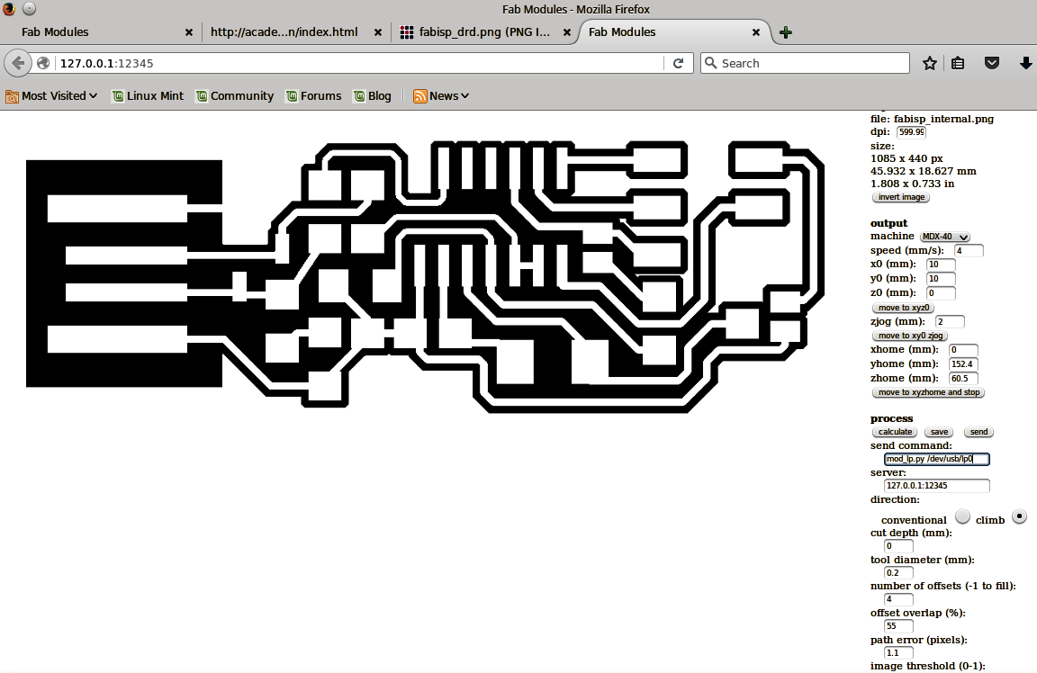
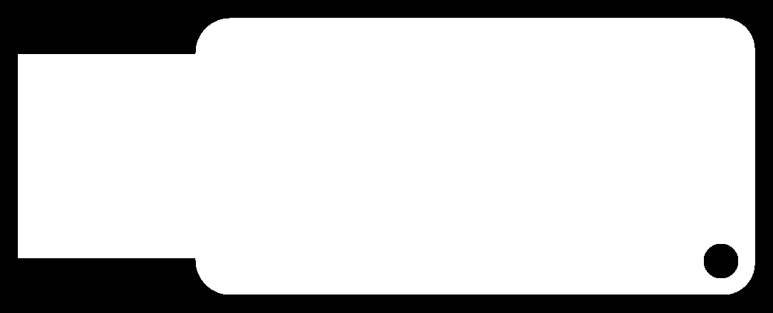
For the external path, we follow the exact same procedure while changing the tool in the machine to a 1mm diameter one and some settings to:
Soldering
For the soldering, we need the soldering iron which had to be set up in 320oC, the solder, some tweezers and maybe some desoldering copper and vacuum. After getting this equipment, I had to use get the parts needed to make the board. The parts needed were:
In order to solder the board, I followed the schematic below and the sample board of our instructor.
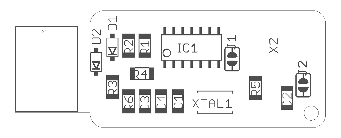
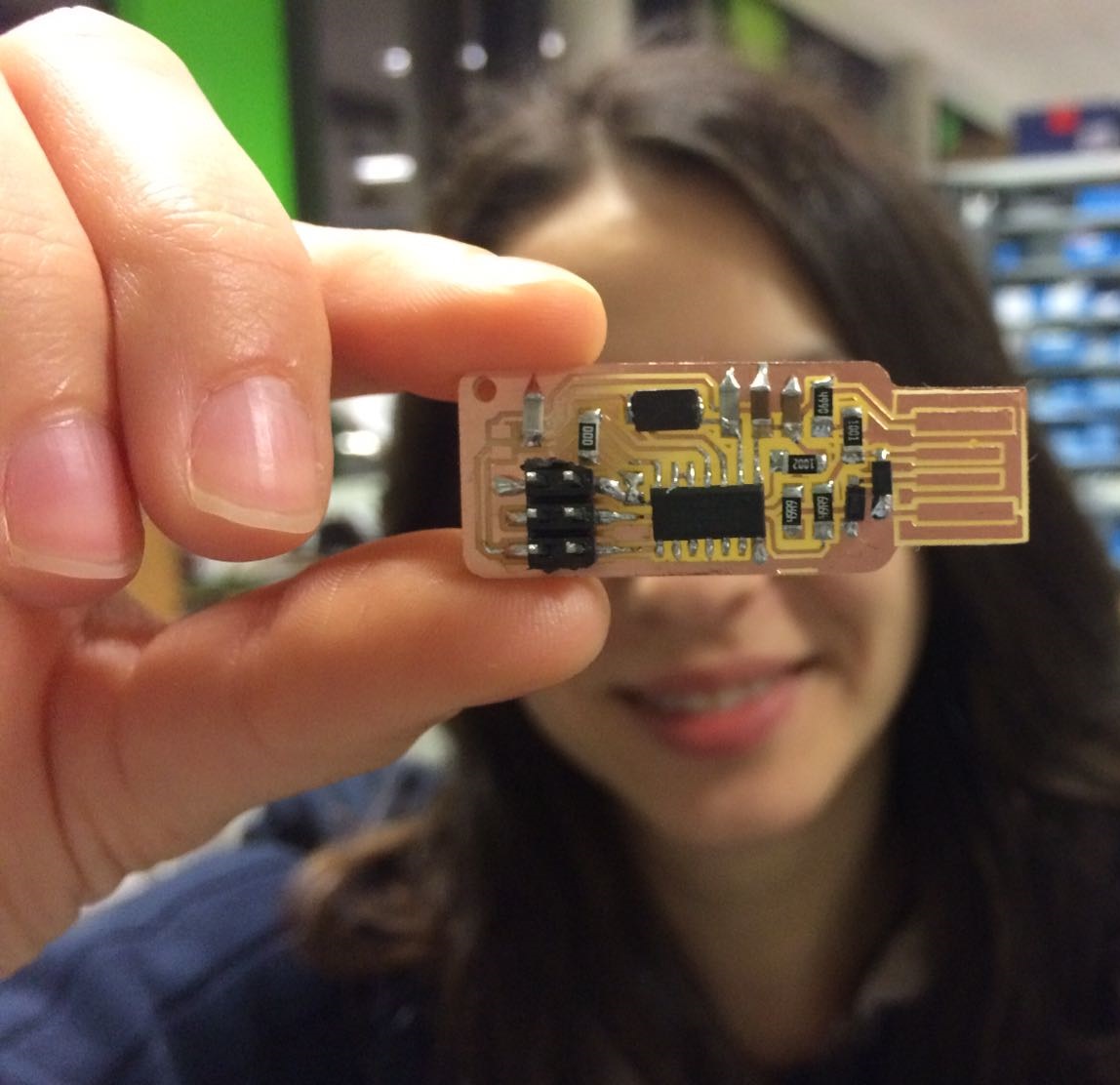
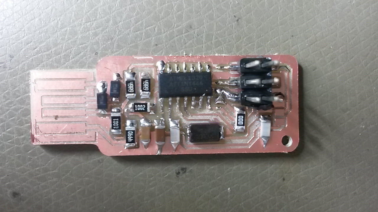
The soldered board, finally looked like this:
An important note here is not to forget to solder jumper 1 (J1) in order for us to be able to program the board. After programming the board, when we want to use it, then we can desolder it. Also, jumper 2 (J2) is recommended not to be soldered unless we want to power the board from an external power supply.
Programming the PCB
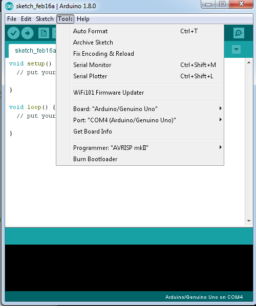
At first, I connected the Arduino to my pc, I opened the Arduino IDE, and chose the right board and port of my connected Arduino under tools.
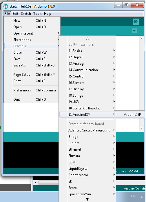
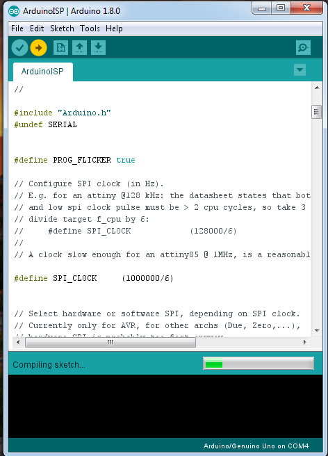
After I chose the right port and board, I found the program ArduinoISP and I uploaded it to my Arduino.
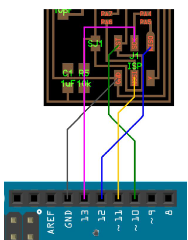
I disconnected my Arduino from the computer and I connect it with the FabISP following the schematic below:
After connecting the ISP with the Arduino, we connect the Arduino again. I downloaded firmware.zip and unzip-ed it to the desktop so that I have easier access to it. Now, in this step I had a problem. As I use Windows, the programming of the board was challenging. I firstly tried to use this manual for windows but it was unsuccessful. So, after that I found Cygwin, a linux based command line that can be used from the windows command line. In order to be able to use it properly, I followed this guide by also adding the nano command on the installation process. Even though the commands this time were recognised it was failing to execute them. So, after playing around with that, I decided to borrow the linux based computer of my colleague in order to program it. For the programming process of the Fab ISP on a linux based computer, I had to follow the following steps after entering to the terminal:
                                sudo apt-get install flex byacc bison gcc libusb-dev avrdude
                                sudo apt-get install gcc-avr
                                sudo apt-get install avr-libc
                                sudo apt-get install libc6-dev
                                 cd ~/Desktop
                                 wget http://academy.cba.mit.edu/classes/embedded_programming/firmware.zip
                                 unzip firmware.zip
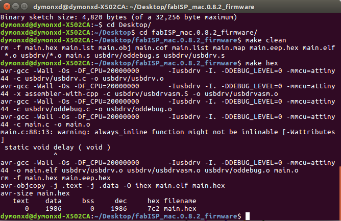
                                make clean
                                make hex
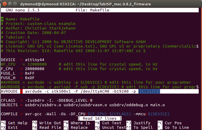
nano Makefile
When I entered the Makefile, I commented the following line by using # in front of it:
#AVRDUDE = avrdude -c avrisp2 -P usb -p $(DEVICE)
And I typed underneath it the following:
AVRDUDE = avrdude -c stk500v1 -P /dev/ttyACM0 -b19200 -p $(DEVICE)
After doing that, I exit the file by pressing CTL+X, I pressed "y" for saving the file and enter for not renaming the file.
                                make fuse
                                make program
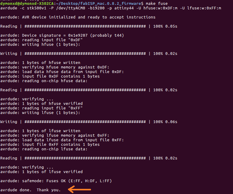
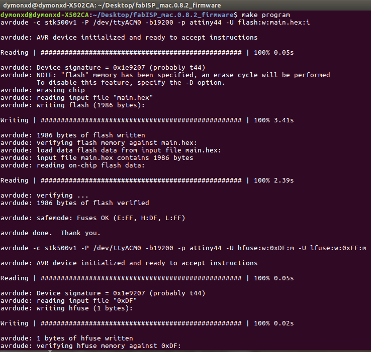
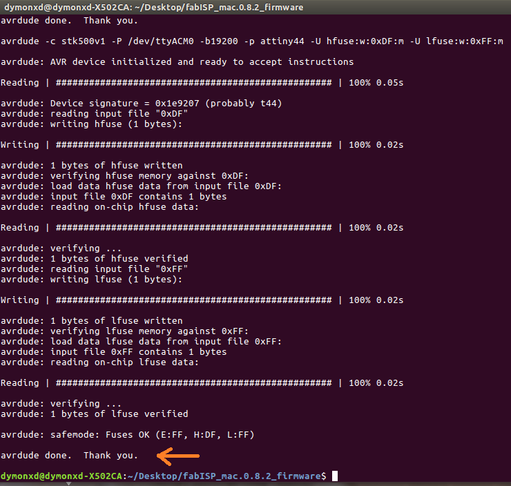
An important note here is that if we are successful, in the end of the executing of each command we have to see the phrase "avrdude done. Thank you.
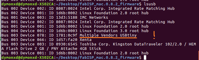
lsusb
Downloads
The internal path of the board can be found here.
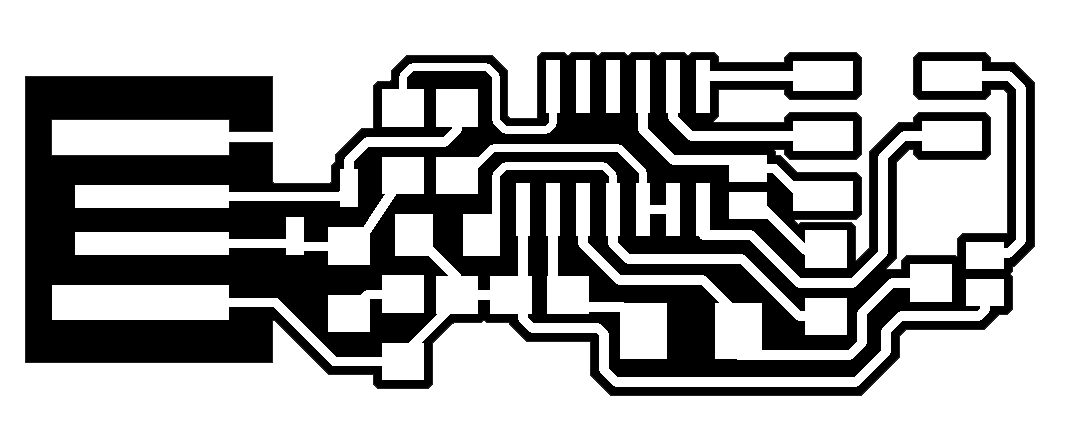
The external path of the board can be found here.
And finally, thhe firmware.zip can be downloaded as a zip file from here.
My hero shot