
Assignment 4
Electronic production
Have you:
make an in-circuit programmer by milling the PCB, then optionally trying other processes
Brian Zaerc Ali Valentin Andy David
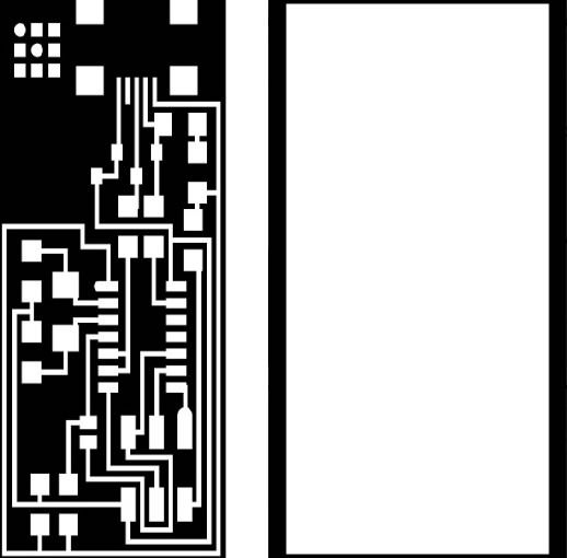
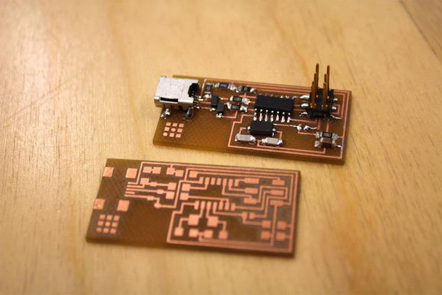
hello.ISP.44.cad board components traces interior
hello.ISP.44.res.cad board traces interior
inventory microcontroller crystal USB connector ribbon connector Zener diode jumper firmware.zip
For this task, initially download the .png files from the card model i chose. in this case it was "hello isp.44.cad". download the file for the milling as for the external cut of the plate.
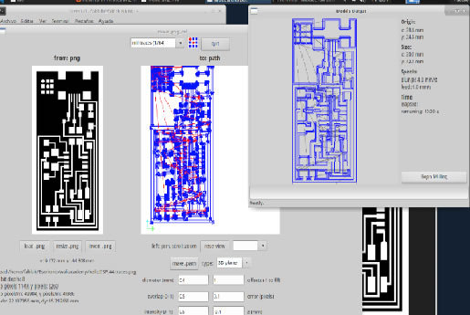
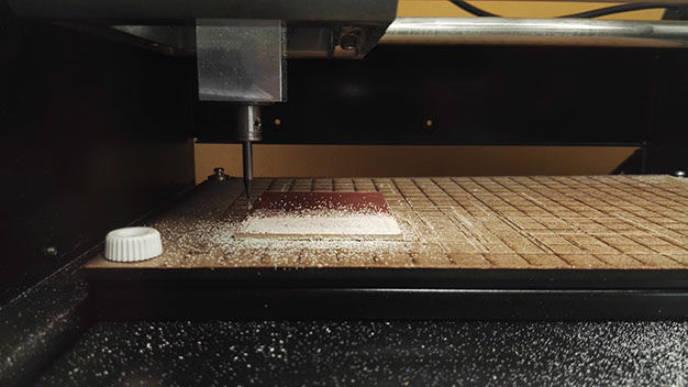
Then, log in to the linux operating system, on the tools menu, click on "open terminal" and i typed "sudo fab", with the password "fablab", chose "png-file" and "modela mx20" image for milling. for this assigment use two types of cutter: 1/64 "(milling) and 1/32" (cutting).
In the configuration make sure to put the thickness of the cutter, change the error number to 0.1 and click on "make path" to visualize how to perform the milling. after this, everything is ready to begin.
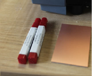
In this assigment work with a simple copper plate, better known as "bakelite", which with the help of a double contact tape, fix on the printing surface of the machine. it isimportant to remember how far from the point of origin is being placed to place it in before starting milling.
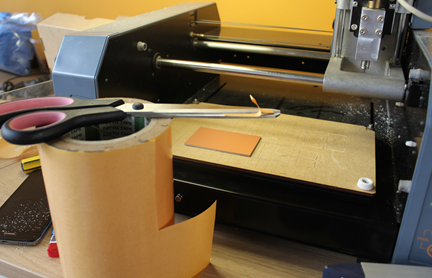
Then, click on "view" on the milling machine, this allows you to square the mill at the coordinates that were placed. calibration on the z axis is manual. one secret i discovered for this step is to press the button, wait 3 seconds and release. so again and again until the strawberry touches the plate, repeat the step once more and there is ready to send to mill.
To order to mill, to repeat the same passage for the cut, changing the strawberry in the machine and in the configuration. after that, with the aid of a spatula remove the cut plate and check if it came out well.
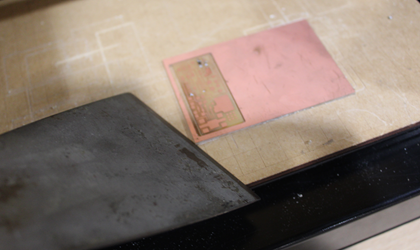
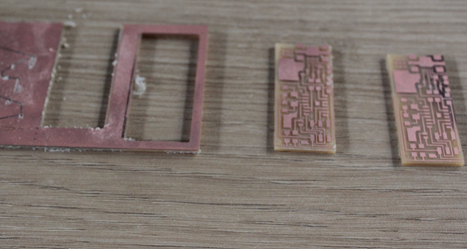
As you can see, it may happen that it has not been milled well, this may be because the work surface was not level. For safety make two or three plates to avoid delays.
After completing this step, see the list of components required for the model plate. one trick can be to note each component and to the side to place a double contact tape. as the electronic components are small this can be very useful.
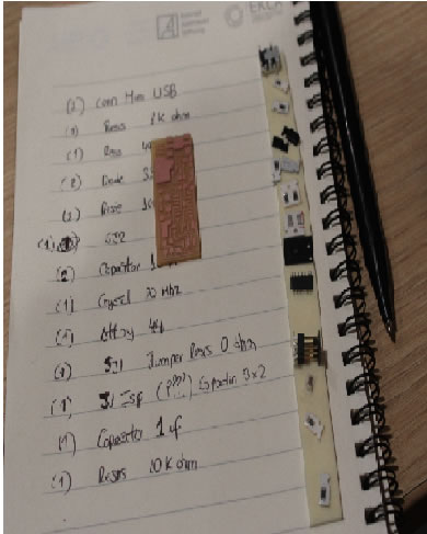
Prepare all the materials that are needed for soldering as well as the image of the location of each component of your plate
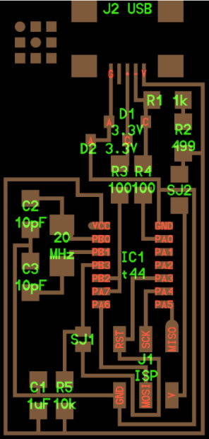
Solder each component according to the graph
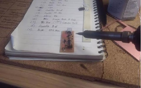
DOING MY ISP PROGRAMMER : Once the components are soldered, we must load the firmware in the circuit, for this I follow the next steps:
1. Power the circuit with a USB connector.
2. Connect the FABISP circuit connector to a AVRISP programmer.
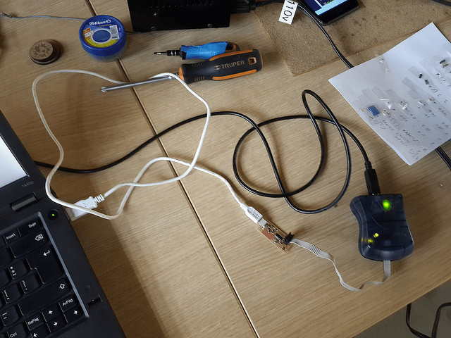
3. Download the ISP firmware in this LINK and then open a terminal in LINUX and go to the firmware directory
4. In this, type Sudo make clean to clean all the previous builds.
5. Type sudo make hex to create and Hexadecimal build of the firmware.
6. Type sudo make fuse, to flash the fuse
7. Type sudo make program, to flash the firmware and the fuse
If entering the programming in the terminal does not leave any "error", it means that I program well
Optional you can type Isusb to verify that the files are stored in the microcontroller.
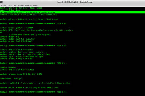
If in the end no error comment comes out that means the circuit was successful, otherwise there could be a badly welded or badly placed component and you should check the card.
In my case, I delayed a lot in soldering the components to the circuit and I was very careful so I did not have an error and program the first one.
However, I had to mill two circuits because the first one did not cut deep and there was continuity throughout the circuit.
USE IN OTHER ASSIGNMENTS : I used this board for programmate a Hall Sensor in the Week 13 and my own board in the Week 6, in the other cases I used the AVRISP