Assignment 6
Electronic design
Have you:
- Redraw the echo Hello-World Board.
- Add (at least) a button and a LED (with current-limiting resistor).
- Check the design rules, make it and test it.
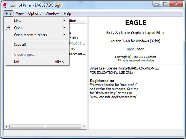
To re-design the hello-world board, first download the software. You can download it at the following link:
www.autodesk.com/products/eagle/overview
Then, you can follow an Internet tutorial to learn how to use it, but, it is advisable to download the Fab Lab library for Eagle.
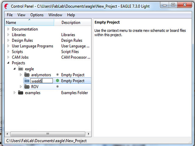
Step 1:Select Create a New Project and name it
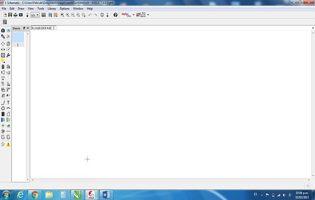
Step 2: Create a New Schematic and Add the library.
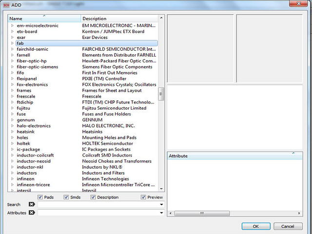
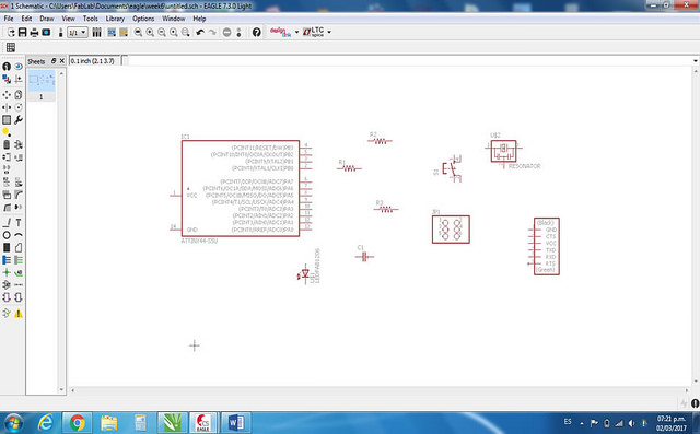
Step 3: Insert the components needed for the board
The components are:
- ATTINY44-SSU
- CAP-US1206FAB
- 3 RES-US1206FAB
- LEDFAB1206
- SWITCH6MM_SWITCH
- RESONATOR 20 mhz
- FTDI-SMD-HEADER
- AVRISPSMD
- VCC (optional)
- GND (optional)
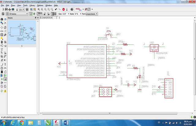
Step 4: Connect components and Complete Schematic
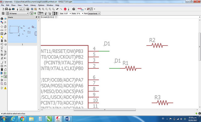
You can use the tool "name" for naming the wires and the tool "label" to show the names in the schematic.
If you are new in Electronic, you have to read the "data sheet" to know which inputs correspond to which outputs.
Step 5: Design the PCB
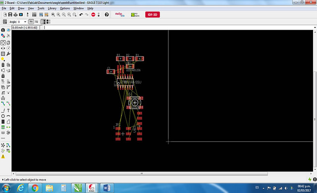
Press "Generate/Switch to board" to generate a plane where you draw the lines between each components connected
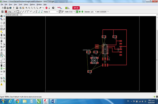
Care must be taken not to cross any tracks on top of each other, since finishing by making short circuit
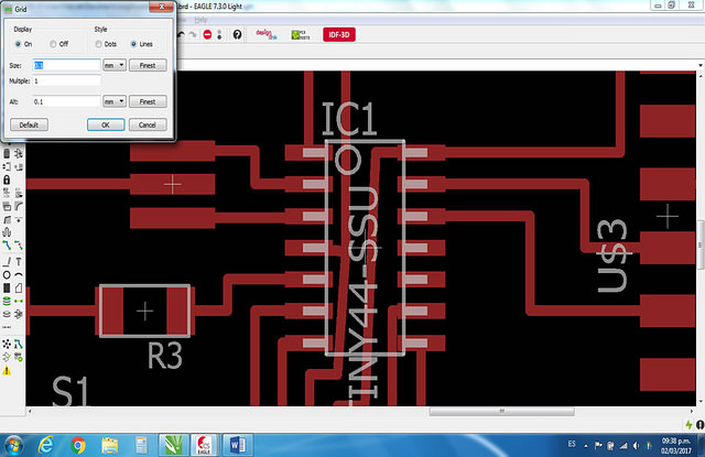
You can change the measure of the layer for you have more space, the measures recommended are:
- Grid: 0.025"
- Widht: 0.0166"
- Clearance: 16 mils
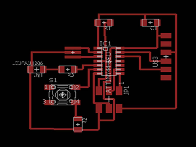
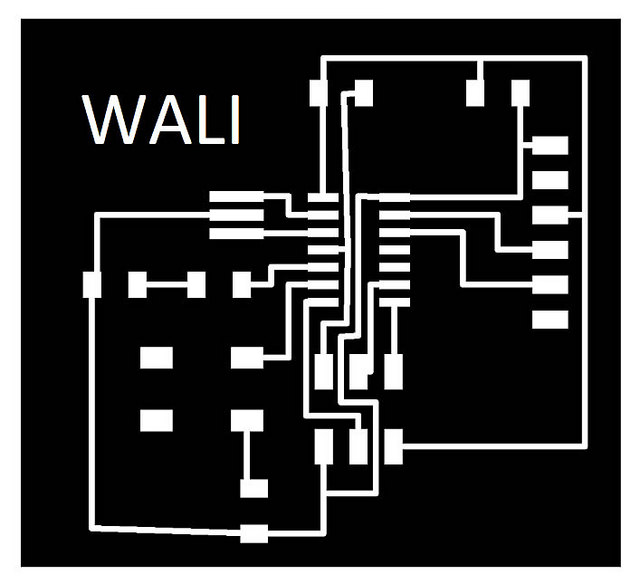
Step 6: Export the PCB and Edit in Paint
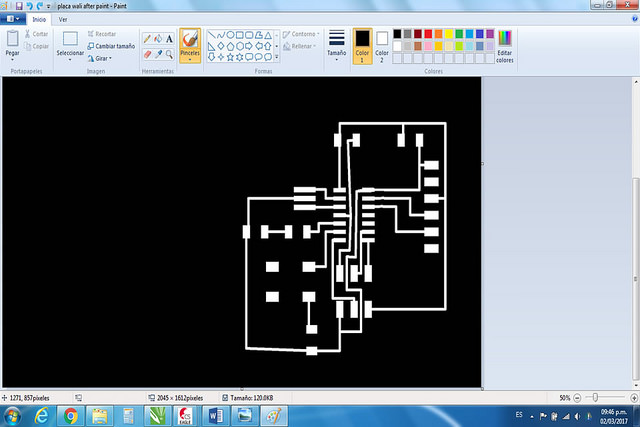
As the "Modela" only recognizes the white patterns as milling and black does not, we edit the image and create a box of the same size to have a cut image and a milling image

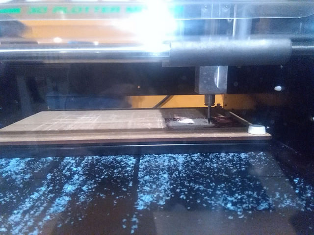
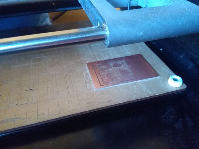
Step 7: Milling a Board
According to Assigment 4, follow the same process to milling a board.
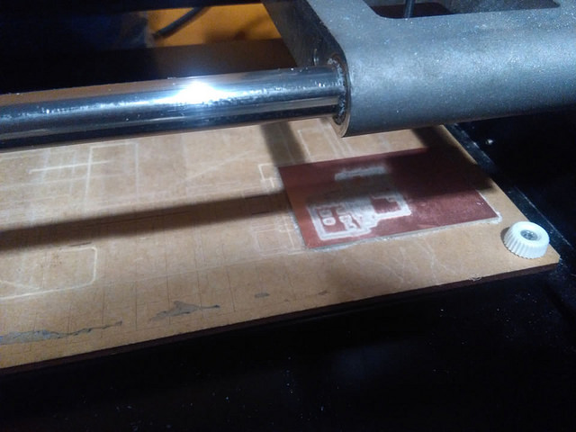
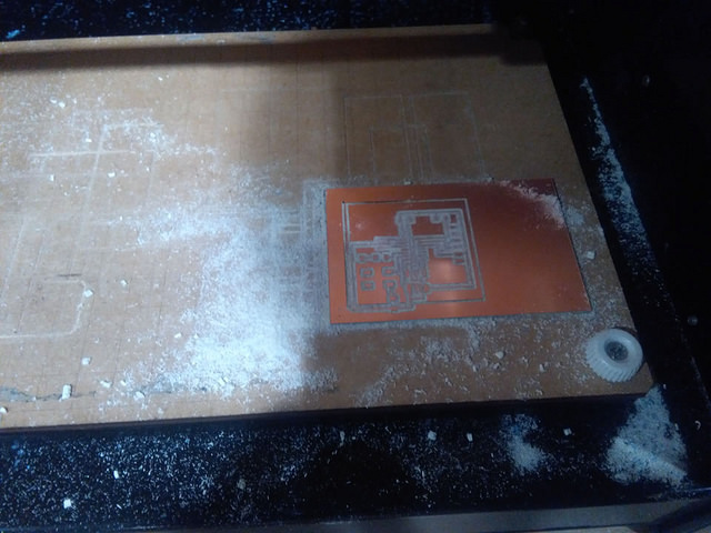
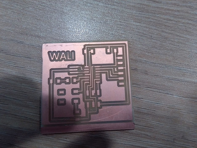
As an anecdote, during the milling process i realized that my board was not designed properly as two paths crossed and i had to re-design
Step 8: Sold the board
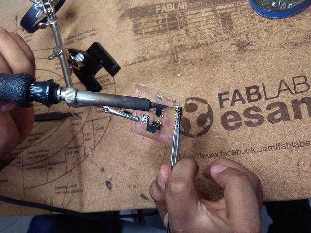
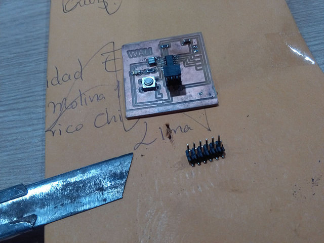
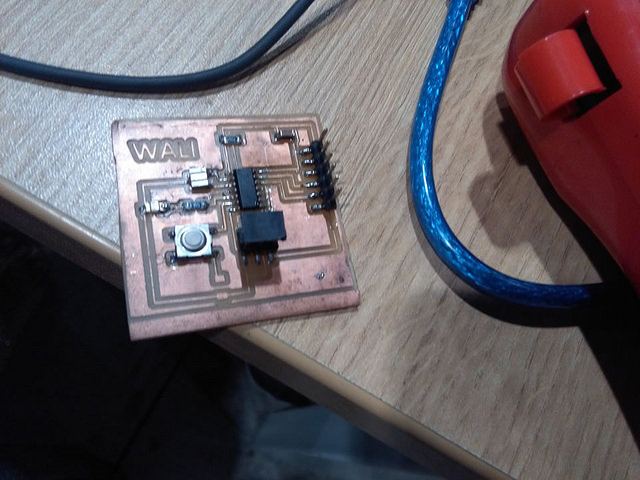
In this case, not have the pin that I designed. For resolve, I cut a other Pin for create my Pin
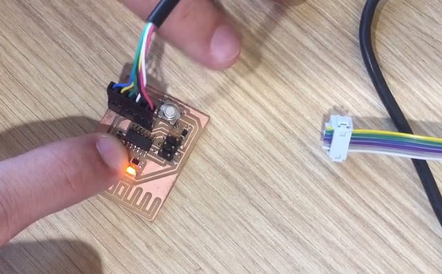
Step 9: Programm your board
To prove that the board worked properly, my friend Duli helped me test it using an Arduino Uno and a very basic program. At first I got error but after checking the continuity on the board and try several times, we were able to program the board.
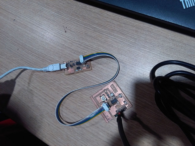
After that, I used the programmer I made on the 4th assignment to burn the bootloader program in the Attiny. For this, I connected the Programmer to the pc with a usb cable and connected the programmer with the circuit by their ISP ports.
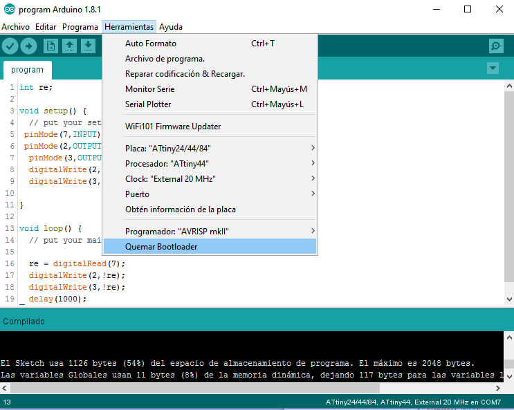
For this, check 3 things:
1. In Tools select the programmer AVRISP.mkll
2. In Tools select the the port that comes out when you connect the ISP
3. In Tools select the board Attiny 44 and the same processor.
If wrong any of the 3 steps will cause errors when uploading
Then, I uploaded the program to the microcontoller for turn on the light when the button is touched.
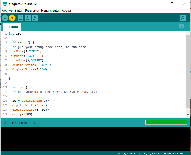
Unfortunately the program was not compiled, check if the port was correctly selected but it was a design error, had placed the circuit track very close to another track and both had the same continuity.
To solve the problem, I had to redesign the circuit and use it to make it more compact and checking the circuit tracks well.
Then, we uploaded the program without problems. When you press the button, the light turn on for 1 second.