
Fab Academy 2017 at Fab Lab Barcelona By Trinidad Gomez Machuca
Evaluate project plan.
Apply time management techniques.
Summarise and communicate the essence of a project.
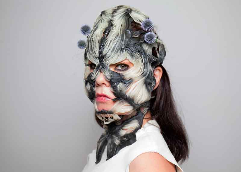
I would like to follow the same process of Rottlace masks for Björk by the Mediated Matter Group and MIT Media Lab but interactive.
Living Mushtari – 3d-printed and generatively grown microbial factory
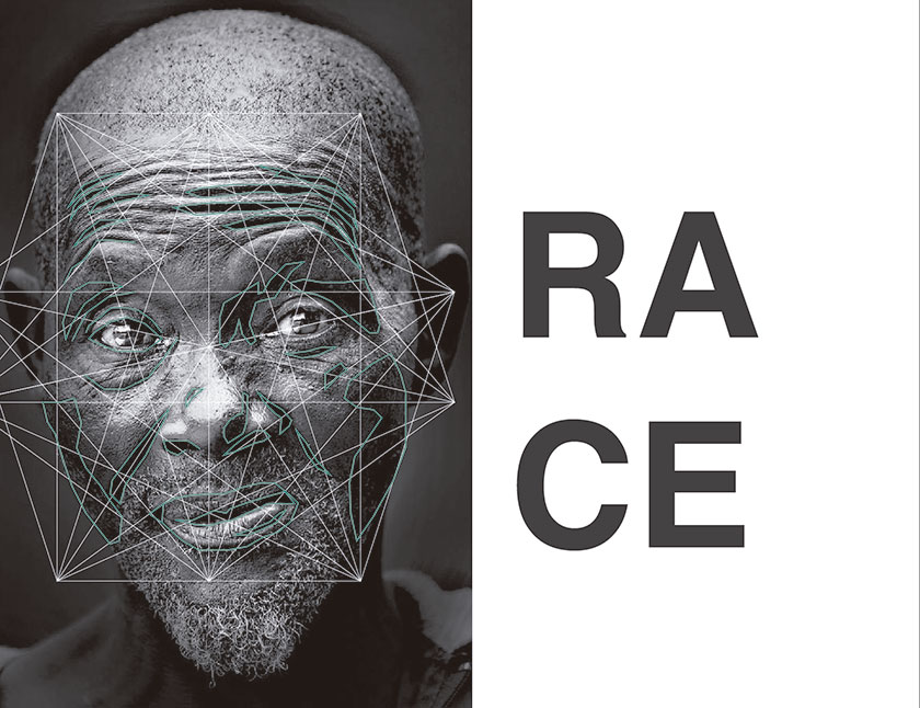
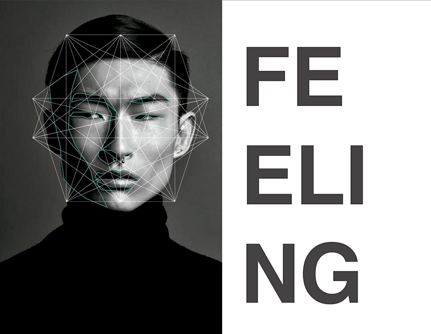
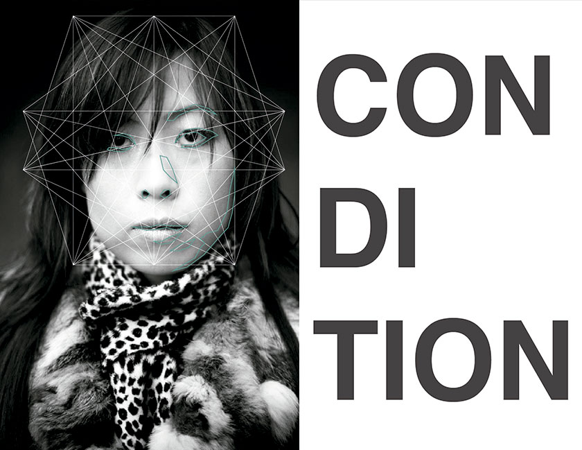
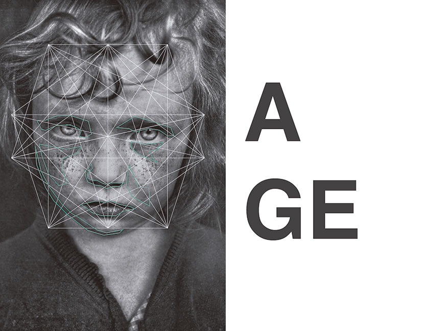
IAAC workshop SKINS 2 ENCRYPTED BIOMETRICS
Other examples
I found a lot of examples of masks that have been made them with the process of digital fabrication. 3d print are the most common but the purpose of all of them are the same, only to play with the algorithm of the data of the 3d images and show a parametrics or aesthetic result. Only one of the examples that I found was interesting. The Facial Weaponization Suite because they are against the face recongnition algorithm that governments use to identify infractors in the street since they are looking for maintain their anonymity, the only thing is that theire result still being aesthetic.
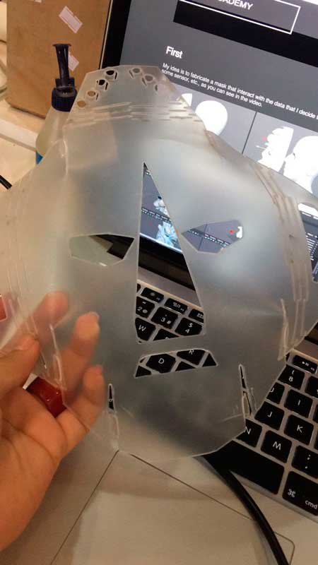
My idea is to fabricate a mask that interact with the data that I decide to show through the face. Depending on the amount of information, it will expand, change color, activate some sensor, etc., as you can see in the video.
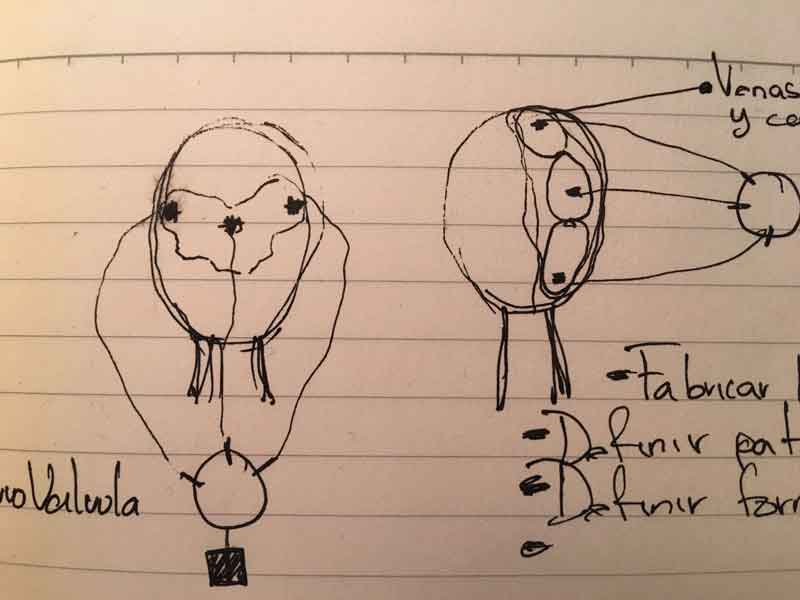
What is the purpose of the face besides to provide to the brain the main input information for the brain? image visualization, smell, taste, sound, touch but from the perspective of the other people, face is used for identify fisical aspects and then reac. What can we read in a face? Age, gender, health, et. to carry a device that can transmit the information that we want to show.


Wikipedia says that Soft Robotics is the specific sub-field of robotics dealing with constructing robots from highly compliant materials, similar to those found in living organisms. [1] Similarly, soft robotics also draws heavily from the way in which these living organisms move and adapt to their surroundings. In contrast to robots built from rigid materials, soft robots allow for increased flexibility and adaptability for accomplishing tasks, as well as improved safety when working around humans.[2] These characteristics allow for its potential use in the fields of medicine and manufacturing.
I really think that soft robotics are fascinating, i want to learn how to control one. But honestly i want to learn how to make this is because I'm planning to do other projects with a comertial porpose and As you know all academies projects has to be open source so it will be a good exercise to practice now.
Here you can find some links that i followed to understand this kind of robots.
Soft robotics Air power Example from Instructables
Soft robotics Examples from Instructables
This is my plan, for my final project I want to program a interface in python or processing that will show in real time data the information of my inputs. Then program all the hardware in arduino and when i understan well I can do my own board, and fabricate the mask with the same material for the soft robotics, the ecoflex, only if I have time I'll try to do it with a bio plastic.
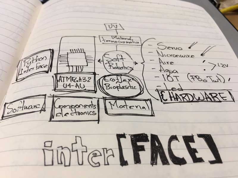
For the fabrication I will need only the ecoflex combined with thermochromic dust that will allow to change the color of the ecoflex depending on the temperature. I will do the mold in the CNC or the 3d print.
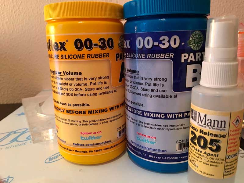
Ecoflex 00-30 the ecoflex is the most flexible, I researched what kind of material and the most common one was this kind the 00-30.
Thermocrhomatic aditive. This material is expensive and hard to find but it is very cool to try.
Nichrome wire this one you can find it in a Stationery, is commonly used for cutting foam materials, depending on the volts that you used can be very hot and cut or only change the color of my ecoflex.
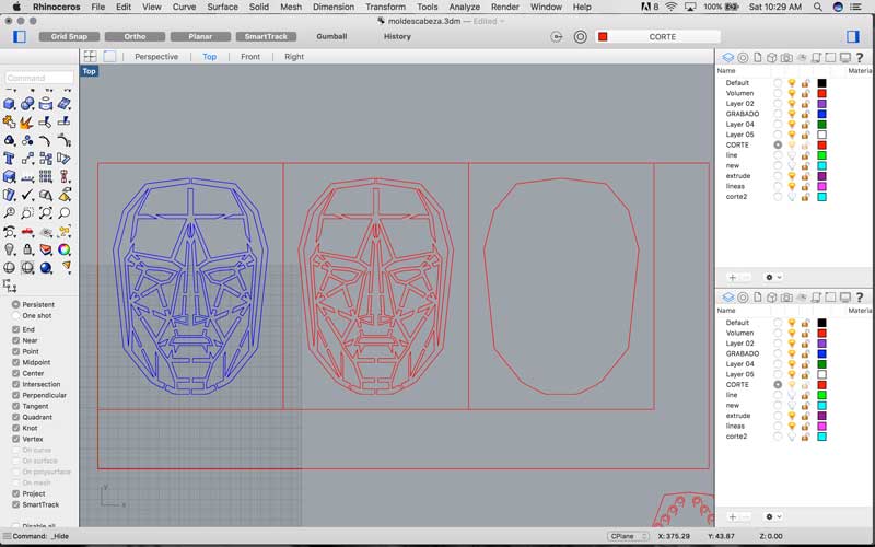
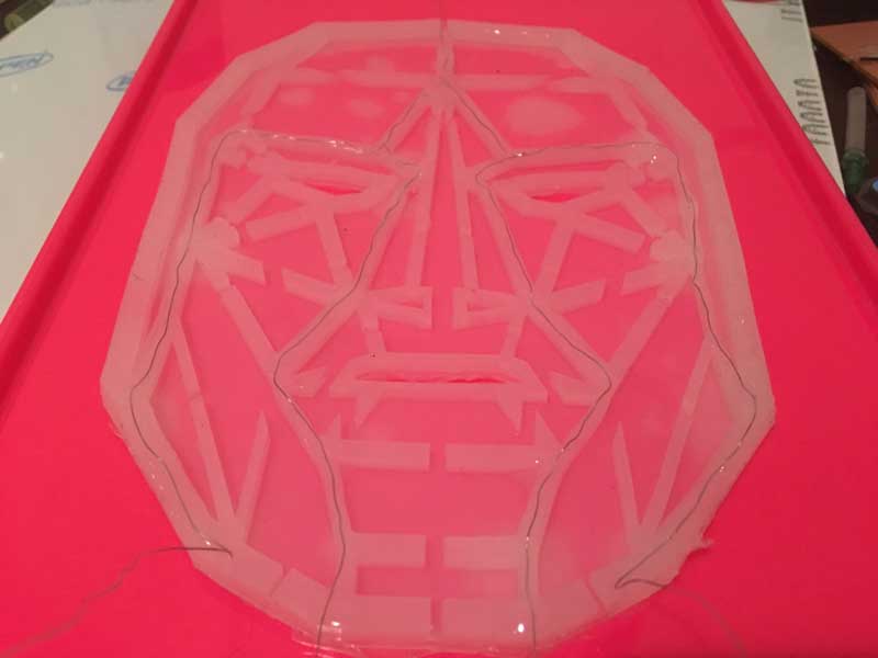
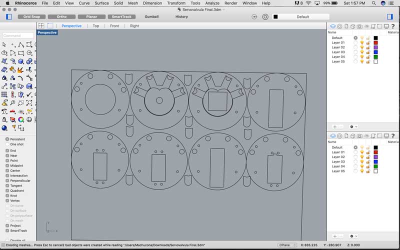
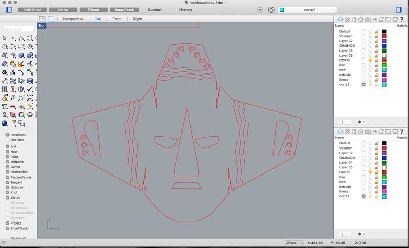
First, I started fabricating the mask with the ecoflex. I used the same draw that I did for the input device in the capacitive sensor. Honestly I was planning to work in a different design for the mask, but now i only have one month left, and i starting getting nervious, so I let the same design, so now i can concentrate in the fabrication of the mask. Here in the picture below you can see the design of my mold, ecoflex works perfectly in plastics so i decided to do it in acrilic, so i draw my base with the engraving of my final design, the middle one is going to be the place where the air is going to enter and the empty spaces is going to be filled with the ecoflex and the last one in the left is going to be the seal layer but in the using the same base but in the other side of the acrilic, so at the end I will have two molds in one piece.
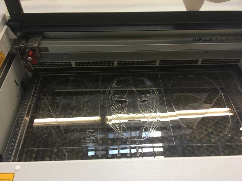
Here you can see how I laser cut my mold.
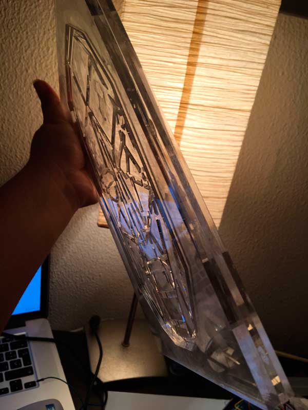
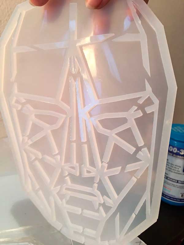
Here you can see the result, the right one is the base, the second one is the mold of my draw and the last one is the mold of the seal layer.
Before to start with the soft robotics, i researched that the best material for doing this is the Ecoflex 00-30, is the most flexible and clean material, besides is very easy to make the combination of the material, the proportions are 50-50 and you only need to mix it very well for 5 minutes and that's it.The other one, is recomended for putting over the excoflex material when this is dry, you put a lot of layers of the liquid. This one doen't allowed to stick between two thin layers of ecoflex.///////////////////////
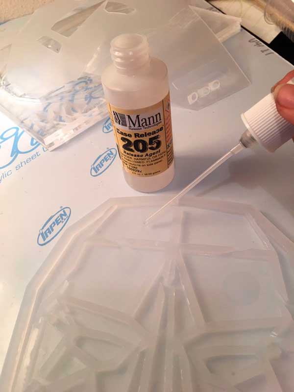
When the two part of the ecoflex are dry, i put this liquid very cafully in the area where I'm planning to put the air so i Can inflate it, as you can see in the image, i put this in the inner areas.///////////////////////
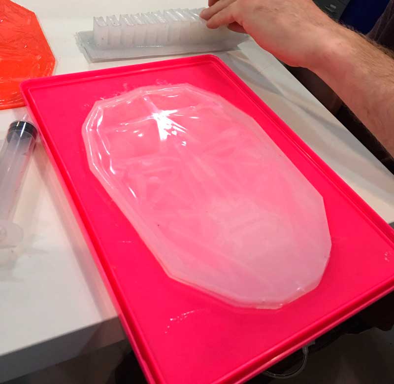
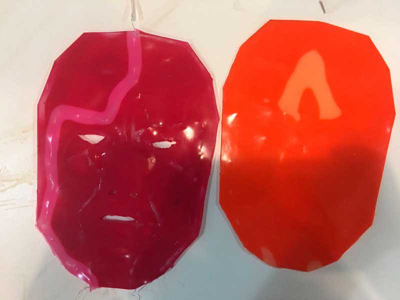
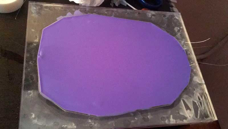
After join the pieces, I put the silicon, in this case in the video you can see how i put the silicon combined with the thermochromic additive, the one that is going to change the color with the heat. My mold is a bit confusing but this is the side of the seal layer.
After it dries, I put silicone in the other side and you can see how easily I took it out from the mold, the acrylic make very beautiful and clean soft robotic mold.
Here you can see the seal layer.Here you can see, when i touched it, it change a bit in the color.
After that, I was confused because i didn't plan in with part of my fabrication process i was going to introduce my nichrome wire, so in my first try I did it manually, I sew the wire very carefully until it get in the position that i wanted, it doesn't look nice but if was the only way i could think in that moment. I had a lot of troubles, because when I was traying to seal it, the surface wasn't plane, I did it like two times and it didn't seal in the inside. So now I have to think how to put the wire in a different way.
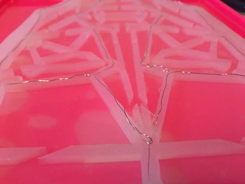
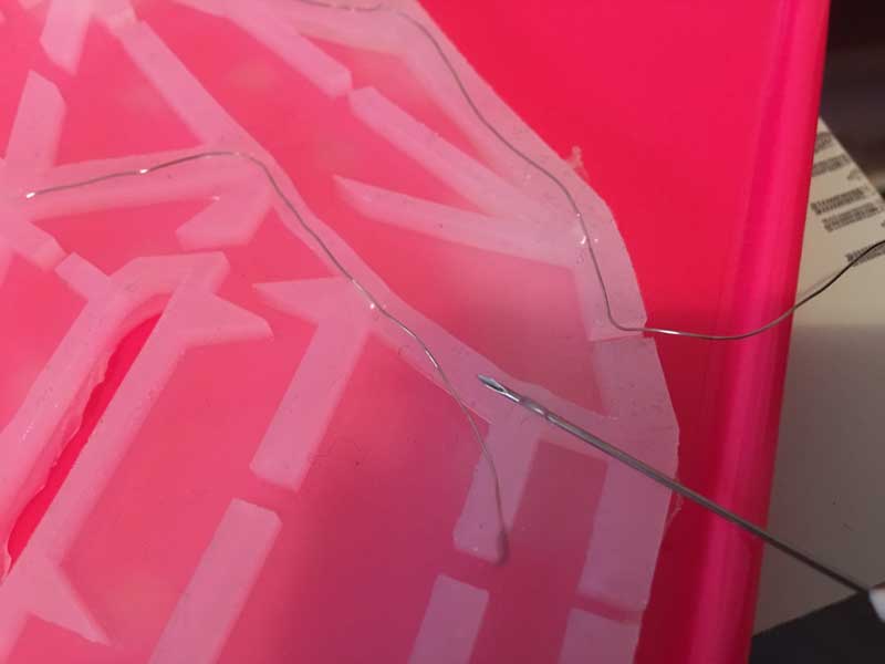
Here you can see in the video how I joined the two parts of the mask with the wire inside, but unfortunately I didn't work, the two layer stick each other, some of the part didn't get together so when i tried to put air inside, It didn't do properly. BIG FAIL
I was stressed because the mask did not work properly so i decided to do one, that works only with air, I did it very carefully. I forgot to say before but when you are using ecoflex for the soft robotics, there is a special liquid that doesn't allowed to stick two layer of silicon, so I used it a lot. I put this liquid in the air areas, It smell horrible but it works perfectly. This liquid is very dangerous so be carefull if you are planning to used it and also, you have to put it a lot of times, wait to dry and put again, and so on. This works!
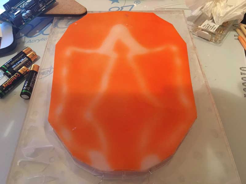
Before to start with other part, even the mask is not working with the air and heat together, i put the layer with the thermochromic additive with the wire just down of it, and I connected it with 12 v energy, as you can see it change the color, with cool temperture is always orange and with the heat it changes to white. Everything was great until I stop the energy and I realized that 12 v is too much for the material, it didn't burn it but, besides is dangerous in the face the temperture that i got, the additive didn't work anymore, so i need to try with a lower voltage.
After one hour without heat, the material didn't go back to its colorful state. It's burned.
The last one before the final presentation. Hope it works.
Here you can see how the color is changing with the high temperature.
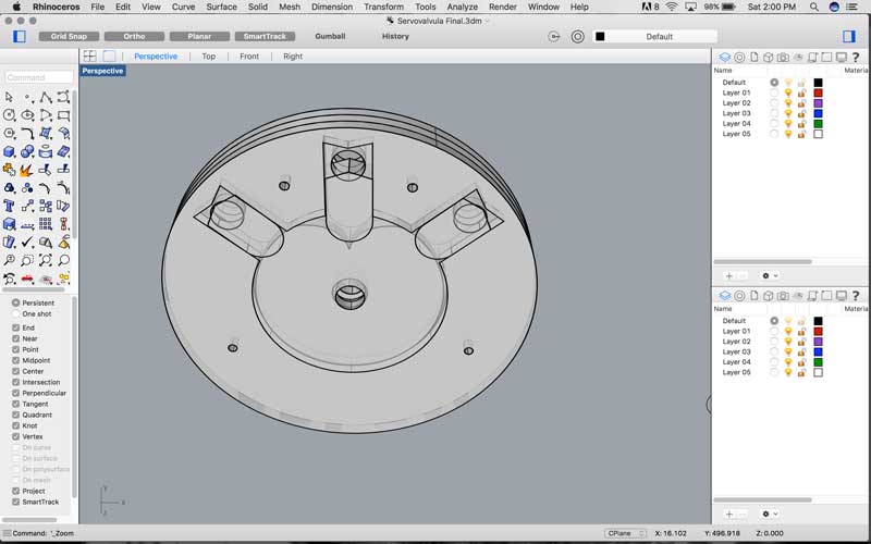
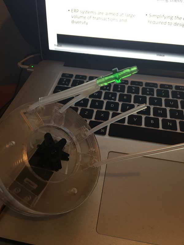
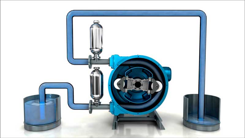
In this part i started to fabricated a servo valve, I didn't designed by my own, two years ago we invented it in the lab where I work togeter with my team and one student for a contest, We won a international award in Brazil, but in that time we invented it for a litle irrigation sistem, only three channels of water. I decided to used it because i need to use one air pump but i need to inflate 4 parts of the mask, so instead of buying 4 pumps i change the design of the servo valve for four outputs.
It works like this, when you touch a capacitive sensor, then, first will open the relay and it will activate the air pump, after it will trigger the servo motor, this one will move to the correct angle, in the channel selected, the capsule will be down so it won't press the pipe allowing the air to pass, so this pipe will be connected in the area that you select in the draw of the copper that works with capacitive sensors.
.
In the video below, you can see how it works, I had a lot of problems because I didn't found the proper and flexible hose, the capsule wasn't pressuring enough, so the air was flowing in the four channels. I did a lot of changes, resizing, but when it finally pressed the hose, the servo didn't move because it was a lot of pressure inside, besides when i bought the motor, i confused the type. I needed a servo that respond to the angles not the continous rotation.
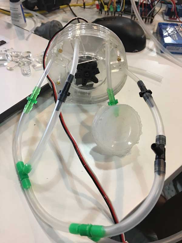
Here I attached to the servo all the pipes, as you can see this is the system that i will need with the connections.
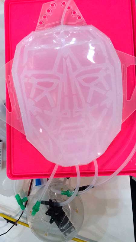
And here is how i connect the pipes system to the mask, every area has one pipe, let's see how it works.
After i finished the the servo mask with the ecoflex, i realized that it is very uncomfortable to have this material over the skin, besides, I didn't think how to attached the mask in the face, So I designed a mask that holds the ecoflex mask. The design was made for attach to the ears and has holes where will pass the hoses.
Is a basic mask but it works for the purpose I've designed it.
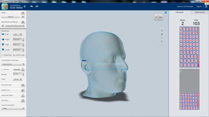
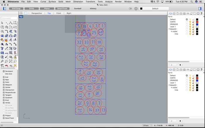
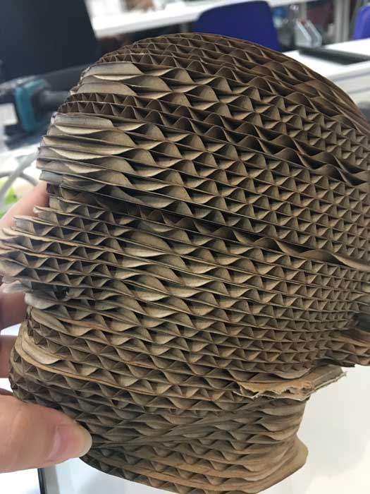
In the last minute, I fabricated a Head for my mask, in 123D MAKE, I only cut the model of a body that i had , and then export it in this program, and the good thing is that it makes automaticly the files for laser cutting.
Here you can see how my capacitive sensors works in Arduino and Processing. I Will do this on eagle when i finished everything.
Hardware OUTPUTS
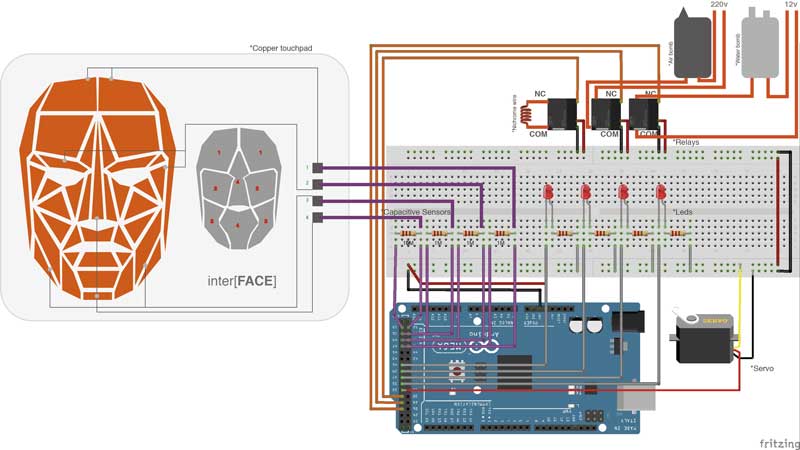
As you can see I'm planning to have only one kind of input, in this case i will use capacitive sensor, a touch pad that triggers something, and for the outputs i want to have leds, servos, air pomp, water pomp and heat a nichrome wire.
// Servo: is for moving something in the mask or make a servo valve that allows to inflate different parts of my mask with only one air bomb.
// Leds: is for see a fast output in the site is readting because the bomb air will take some time.
// Nichrome wire: is for heat the material that I will use for the change the color of the mask. I will mix the ecoflex with a special dust that has Thermochromic properties, this will allow my mask to change the color depending on the temperture.
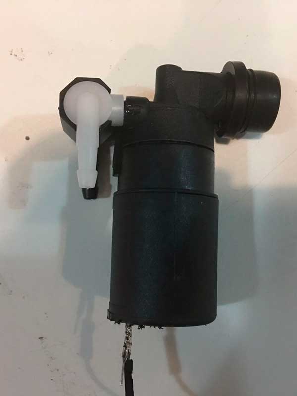
// Bomb air: is for inflate the mask
// Bomb water: is for put cold water inside so i can reverse the reaction of the nichrome wire. At the end of my project, i didn't have time to experiment, i had a lot of problems with the nicrome wire and with the air pomp, but i realize of something, i wanted to manipulate water in my mask but i didn't know how to take out the water, the water pomp that i found was a water pomp for cars, so this one, only take the water from somewhere and put in other side, one week before the final presentation of the academy, i saw some else project that was manipulating water and this person toldme about Peristaltic pomp, if this one you can programe to pull and take out the water, or you can use two, one for take in the water, and other that take out the water. I already bought it, I'm very excited because I've never used this one, so when I had time I'll start working with this one.//////////////////////////////
Water pomp.
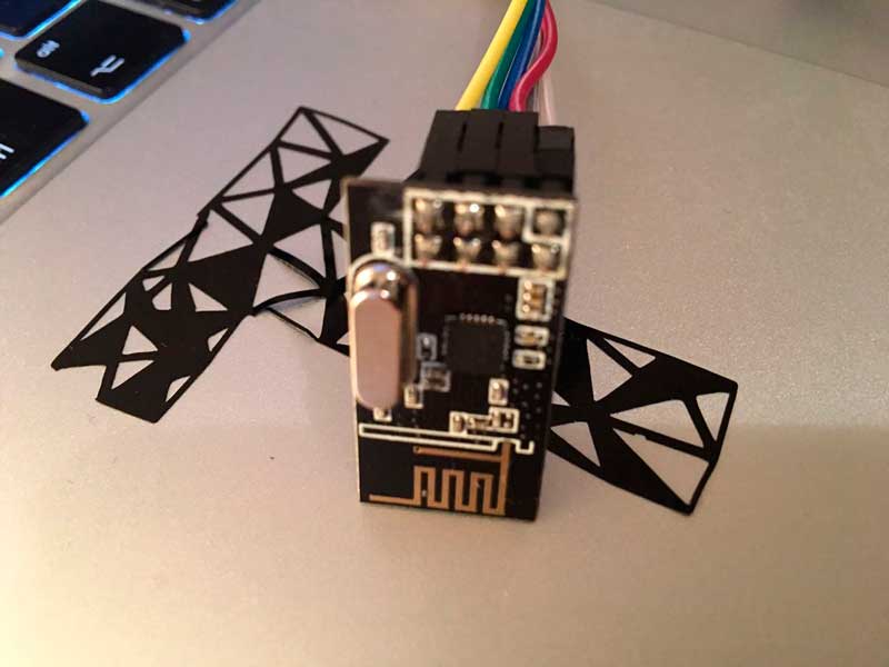
// Iot: I really want to experiment with this but i will do it only if i have time, honestly i don't know nothing about electronics so i hope i can do it. For the Iot device, i wanted to use for controlling the nicrome wire, so this one will be connected to the internet, i was planning to conect it to a twitter o fb and i can use this as another variable, like show how many tweets do you have and showing in the face.////////////////////////
WIP
The purpose of having a lot of outputs is to show different data. Every part of the mask will mean something. For example, if one part change the color it will mean that this area is activated because the person is happy. Yeah, something like this hahahahaha.
Software
I would like to use Python or processing. Here you can see my assignment where i programmed my interface in processing for my final project.
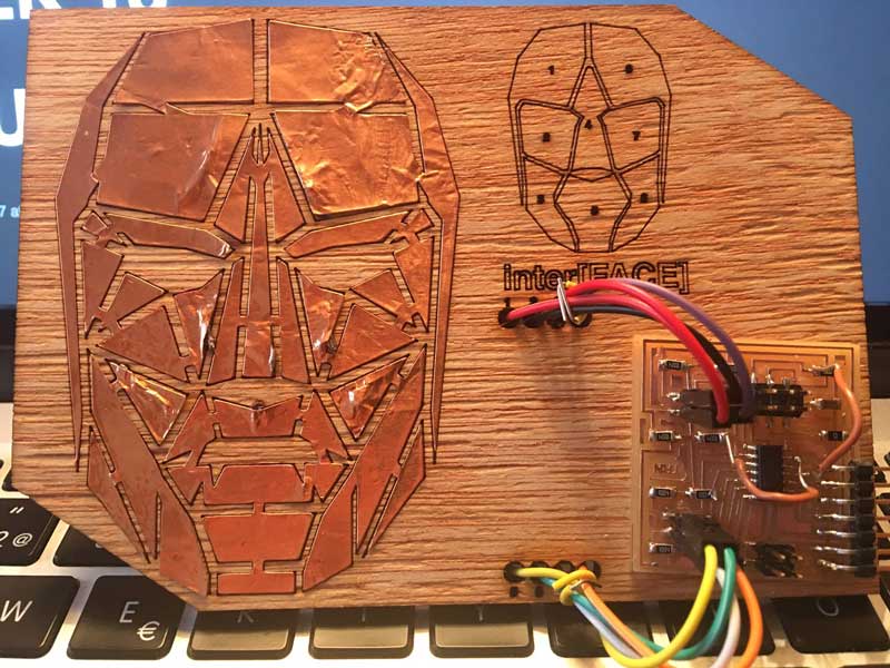
For this assignment i want to try python and processing. I already know what to do for my final interface, i designed a face in rhino, that i made it also in copper with the vinyl cutter, and i've programed it like a touch response with the capacitive sensor. In hardware, when you touch the copper, it triggers a led, a air pomp, servomotor, etc, but in software everytime i touched the copper i want to visualize exactly the area that a i touched, so i will see wich one is better for what i want.
First i wanted to try to make my interface in Python code, but I got so many errors that took me one day to fix them and I need to work in my final project. I tried before to programming in python and in my opinion is not difficult lenguaje but my problem is that i just can't fix the problems they appear, i read the comments from a lot of people like me that are starting with this lenguaje, but I just could not fix it.

In this case I've installed the Serialpy library wich is the library for the exchange of information between arduino and processing, but it alwaysappear this error so the farthest I've come was to draw manually my draw with the command turtle. It is easy and funny if you are not doing a complex draw. In this case i did line per line and when i finished one half I mirrored the coordenates for the other half. At the end of my draw i just trigger when you click over the circle to disable it and when you press the up button from my keyboard it activate it again.
So after python I decided to go for the easiest, Processing. I'm familiar with this lenguaje because I used before in my master with the kinect. Besides that this lenguaje is very similar with the interface with arduino, is very easy to find how to do something and how to fix a problem because there is so much information on internet that even a 5 year old kid can install a library hahahahahaha.
So the best tutorial i found was this one, Sparkfun tutorial for Arduino and Processing. Here you can understand how this two can interact together in the both ways, either you want to draw a button in processing and trigger a servo in arduino or when you receive data from a sensor you can visualize in Processing. It's a very good tutorial and the best that you dont need to connect nothing, only the arduino, no jumpers, no leds need, anything, so this make your first exercise very easy.
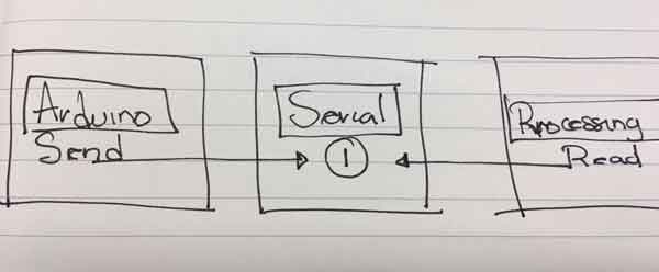
This is how it works. First you have to decide which one will send the data, in my case i want to trigger outputs depending on the capacitive sensors, this i do it with arduino,so Arduino will send data. Then when the processing read this information, it will show in my 3d drawing with part you touched.
Is very IMPORTANT to know about what kind of variables are you sending, I didn't know this before and it took hours to fix it. In the this video in the 5 min, you can what i mean. Something similar happend to me, i was sending int variables to the serial and in my processing was reading other kind of values. Although I was sending the number 1, the processing was reading the number 10, but the problem was the kind of variable, you need to send this information as a byte inter, after this, everything was ok.
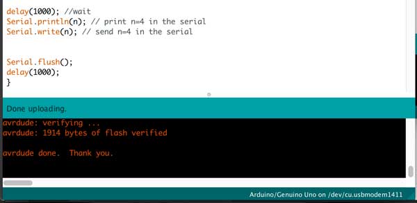
After declare my variables as bytes the only thing i want to do, before to put this code in my final programme, is to send to the serial 4 diferent numbers, thats it, so here you can see i used a delay and send one variable, then delay and send other variable and so on.
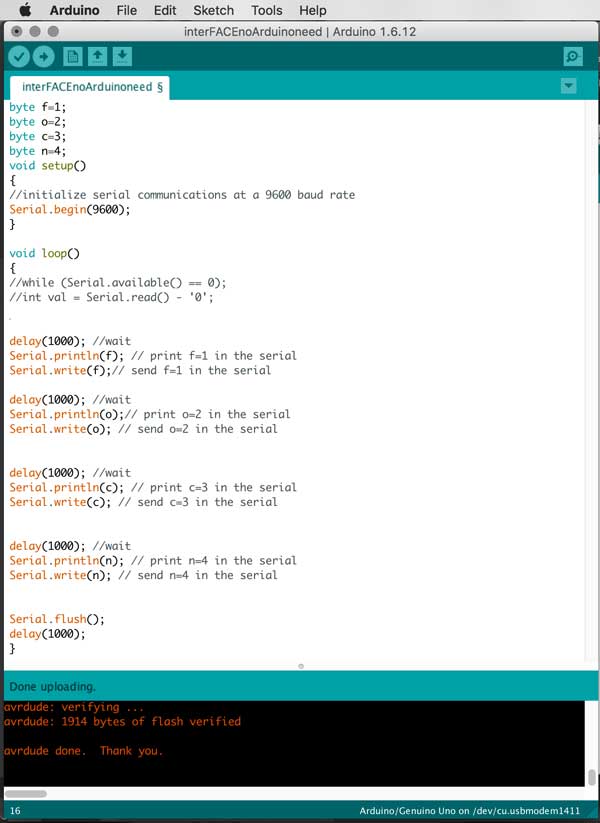
Here you can see the code that I sed fot sending information to the serial port and eventually after sending, I read the bytes data in the Processing.
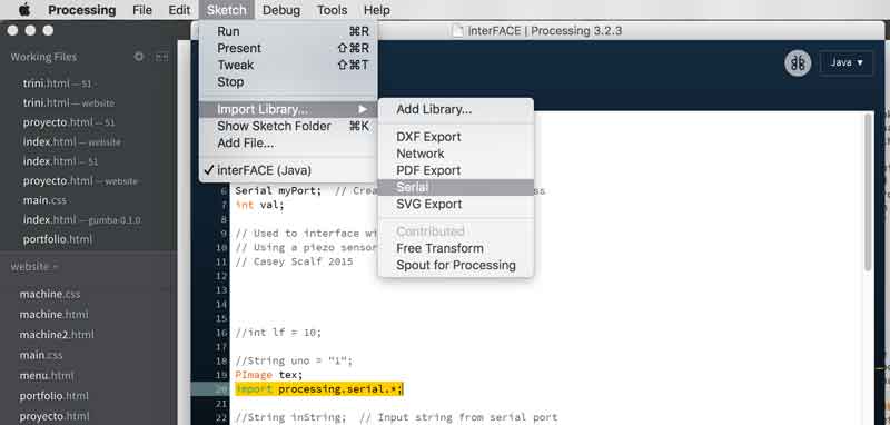
First the Serial library. Serial library is already installed in the processing, so the only thing you need is to call it in your program.
You have to write the number of your port, the only options in mac are 0,1 and 2. In my computer is the number 1, i know because this is the only option that allows me to see information.
An here is the part where you read the data and compare. So i'm telling the Processing, if you receive information bigger than the number 0, stored in the val variable. Then if this val is the same as the number 1, change the color of my object, if not, let the object with the default color, in this case white, and so on. In arduino I'm sending the information every second, that is why is changing color all the time.
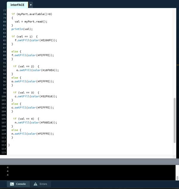
Here you can see the code that used to read the information in the Serial port and then I changed the color of the 3d models that I sed to visualize which part it is being touched
In my final project, every time i touched the copper I triggered outputs and combined with assignment i also sending the byte variables and i can see it in the processing digital draw.
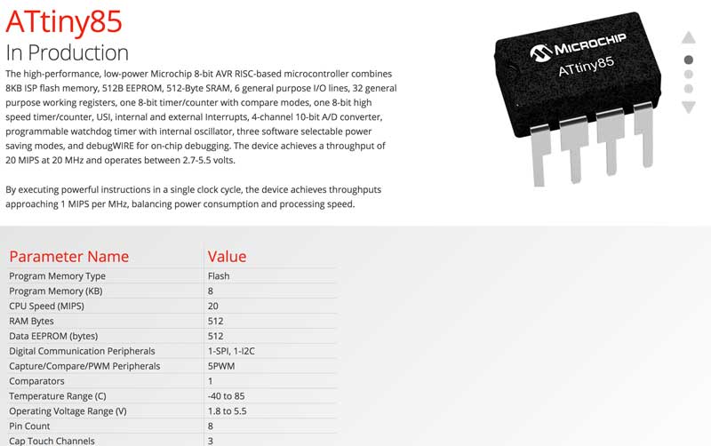
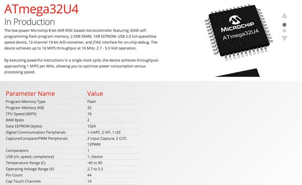
When i was doing my input device assignment... I fail, but i've learned a lot about the properties of the microcontrollers. First before to choose a microcontroler, you have to know how many data you will store. In the input assignment i choosed to do a touchpad, for this you have to use capacitive senros. I you want to progam it in Arduino you will need to install the capacitive sensor library, this is the only way you can see if your sensors are giving you back in the serial port. But in the example that i was following they use a attiny44 microncontroller, a library and the code it was too much information for this attiny. So at the end i have to follow the same squematic but with other attiny. I followed Attinny44 datasheet, Attinny85 datasheet, and so many until i found the right one. For the time i want to pass directly to applied the capacitive sensor in my final board, with i will use a atmega32uf, the best one for doing a lot of task, at the beginning i wanted to used only for capacitive sensors but i realized that is a very powerful microcontroller that it will be a waste if you only used for this.
This is one of the reasons that i did all my circuit in the Arduino Board first, so i can know how many bytes i need to run all my code. You can know this information when you compile your code in Arduino, at the end it shows how many bytes you are using, so depending on this, you can choose a micro controller.
And here you can see how many bytes this microcontrollers can store, in the RAM bytes.
So before to start doing my own board for my final project i decided to do it first in the Arduino mega, So i can understand for complete how everything is connected and the also i want to understand all the code. I did not know a lot of things, like how the relays works, how to connect a nicrome wire, how to put capacitive sensors in the Arduinodirectly, etc. so it was good to do this because now I know and I think is very easy to do it, so I hope i can do it in my final board. After i finished to connect everything, I made this Fritzing/Illustrator diagram.
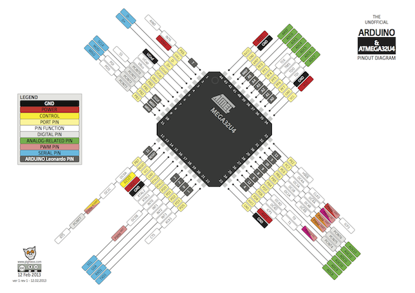
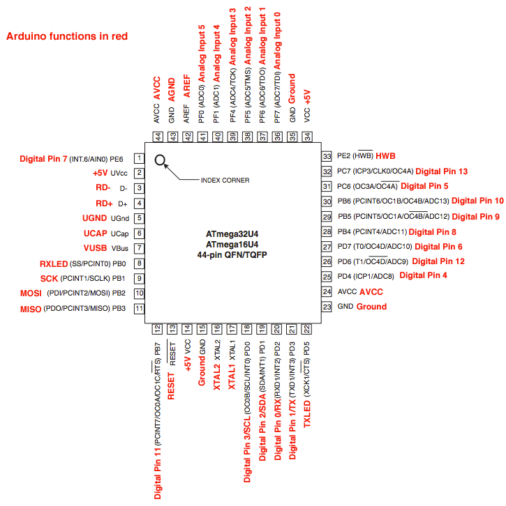
For starting to design your schematic design of your microcontroller in Eagle, you need this kind of data sheet where you can see the pins and change it when you pass everything to your own board. The number of the pins always change from the arduino board to the other microcontrollers. For example if in your Arduino code and board your are using the A1, if you are using a attinny44 you should look the pin number equivalent. As you can see in this diagram, it shows the equivalent pins in Arduino.
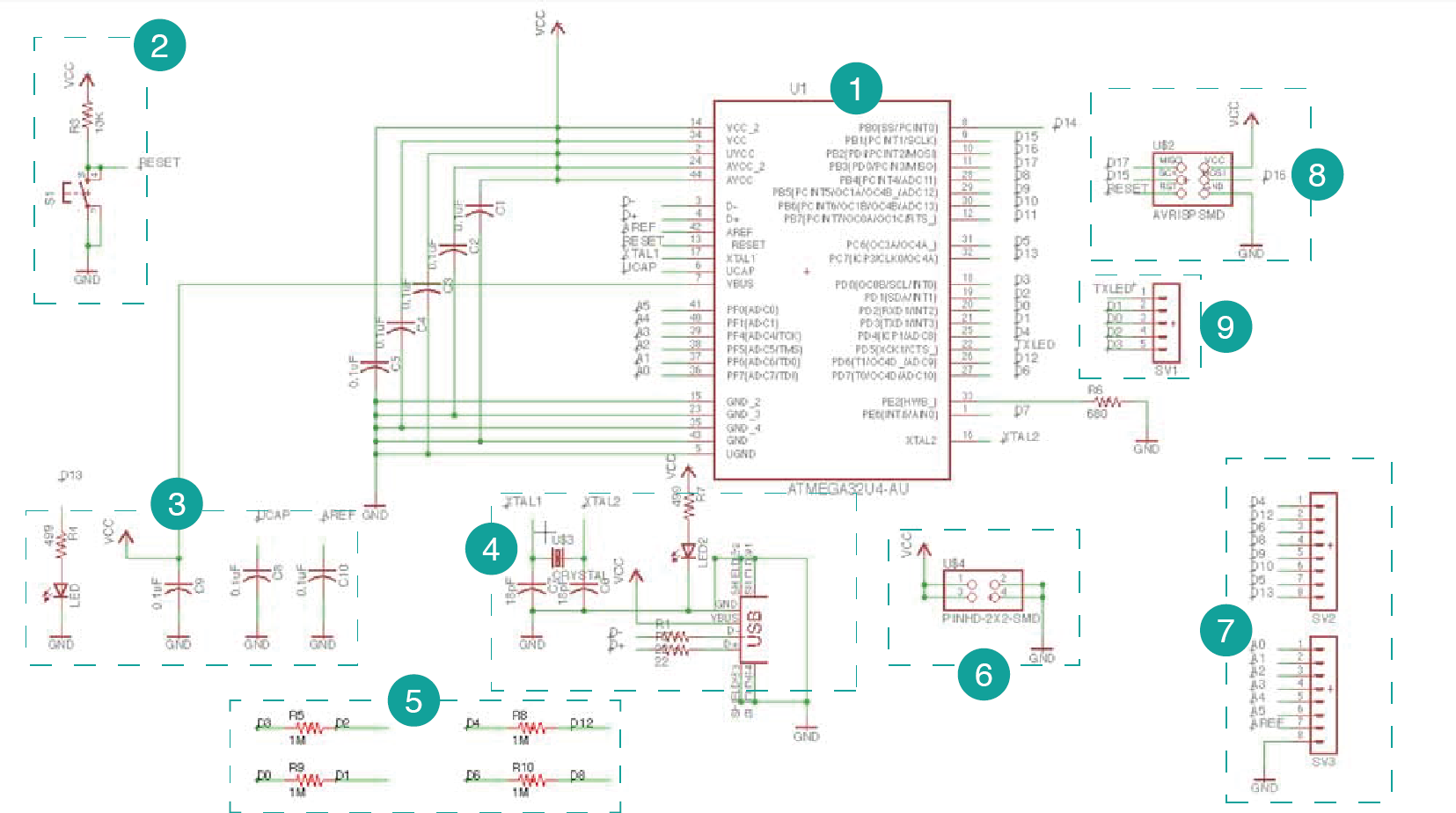
1- Here is the ATMEGA32u4
2- Here is the switch for the reset
3- Capacitors
4-Here is the system for the usb programmer
5- Here is the capacitive sensors for the pins
6-Here is for the external energy, I didn't add a voltage regulator, so here can only be 5 v, if you connect more energy, the ATMEGA can be burn.
7- Here is for connecting digital and analog pins.
8- Here is the AVRISP programmer
9- More digital pins
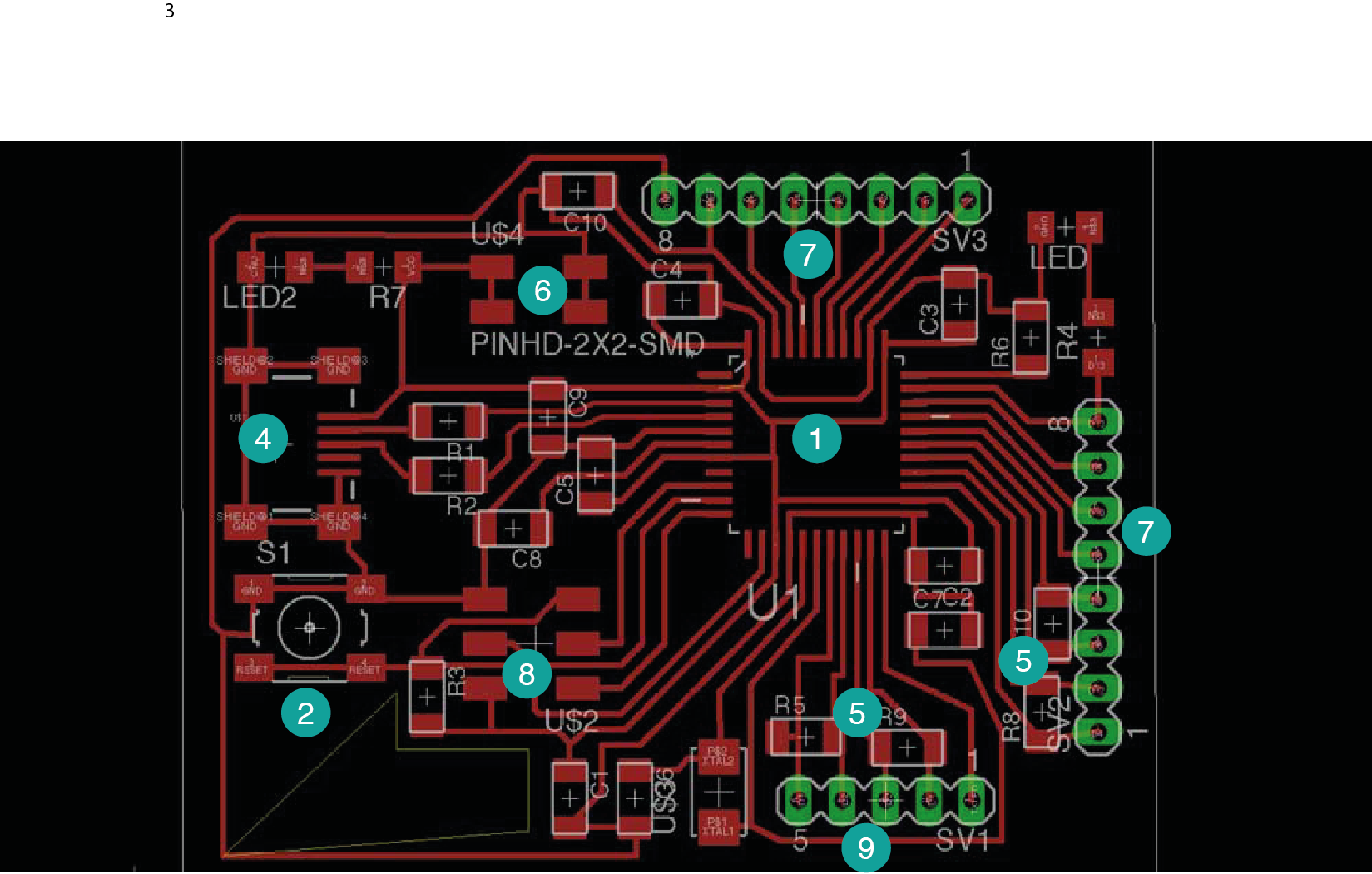
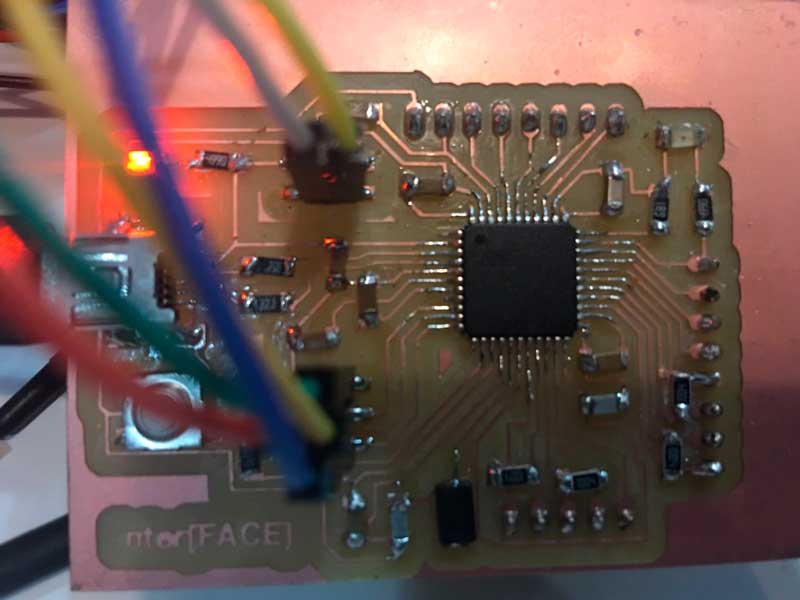
Here you can see in the board how a order my components in Eagle.
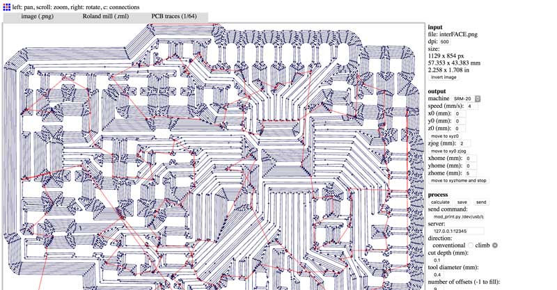
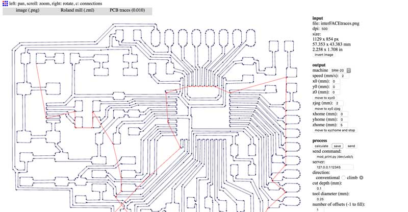
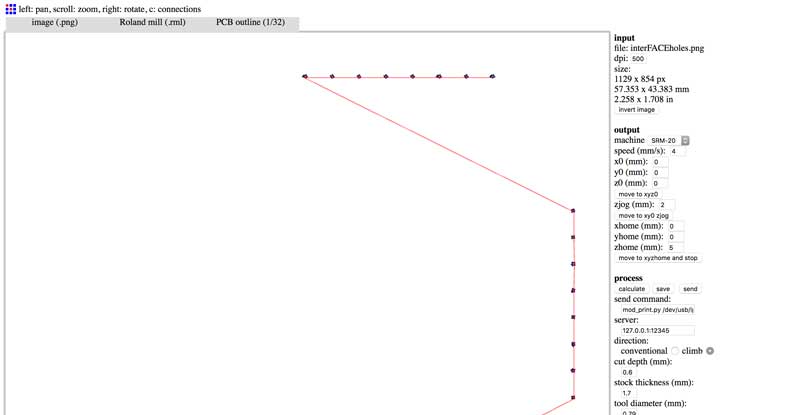
Here are my png files for the modella machine, The first one is going to be for to the 1/34 drill that is for traces, and the 0.01 is for the details that the ATMEGA34u2 need. First one the colors are invert, background should be black. The second one is for the holes, this one has the correct colors.
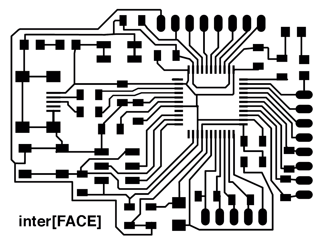
Here I'm using Fab modules for converting the files in c code. So here you can see how the machine is going to follow the path with the different drill bits. Here is very important to make the details with the 0.01 drill bits other wise you will have problems when you solder the Atmega because the 1/64 can not do the tiny details, the only thing that you have to do is use the same file for traces but change the settings in the Fab modules.
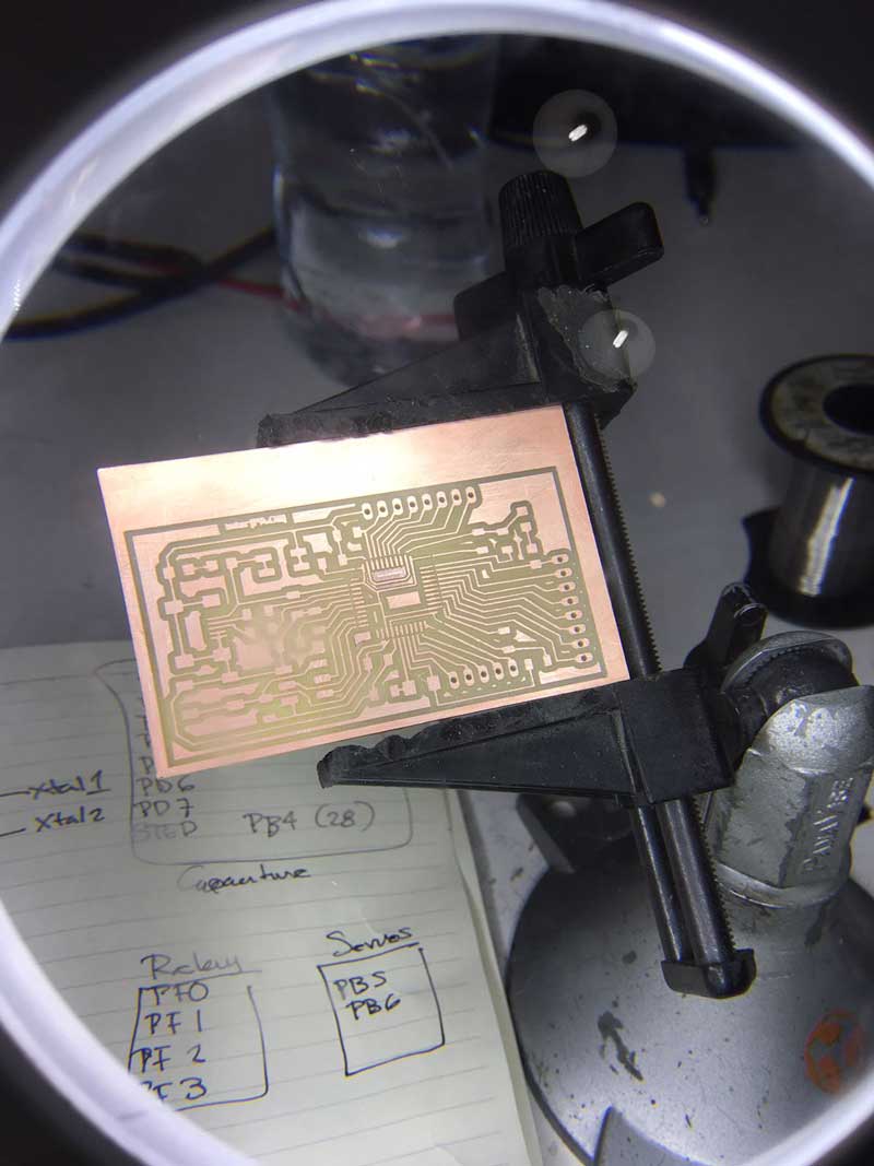
Here is the board milled, so now i will start soldering.
FAILS
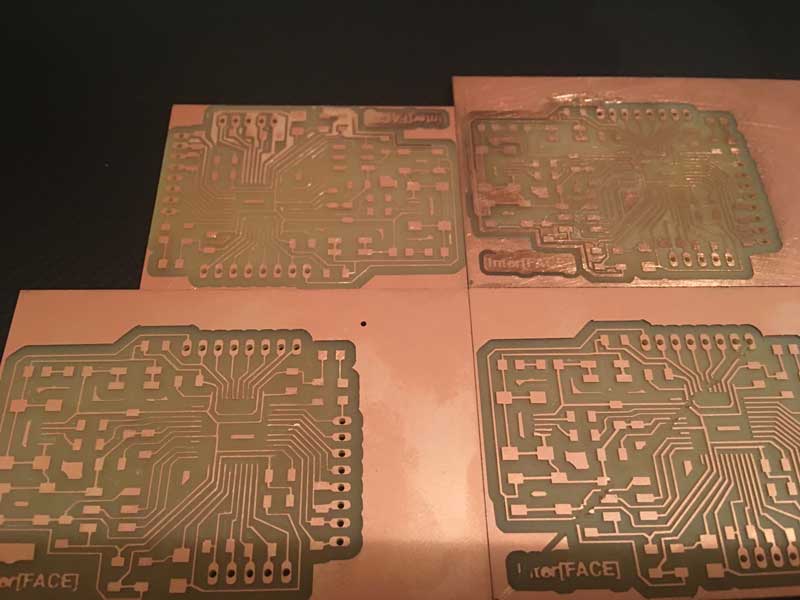
Three weeks before the finals, I was trying to fabricate the Arduino Leonardo, the first one worked the milling, but not when I solder it, I couldn't do the bootloader in the Arduino, so i did it 4 more times and always something happened, the traces too thin, some were broken, or the last one it was a perfect one until it finish the holes, it went back to the start point but the drill didn't go up, so it broken all that ii was in its way, I lost one week just trying to milling, so I hope my board works in the last week of the academy.
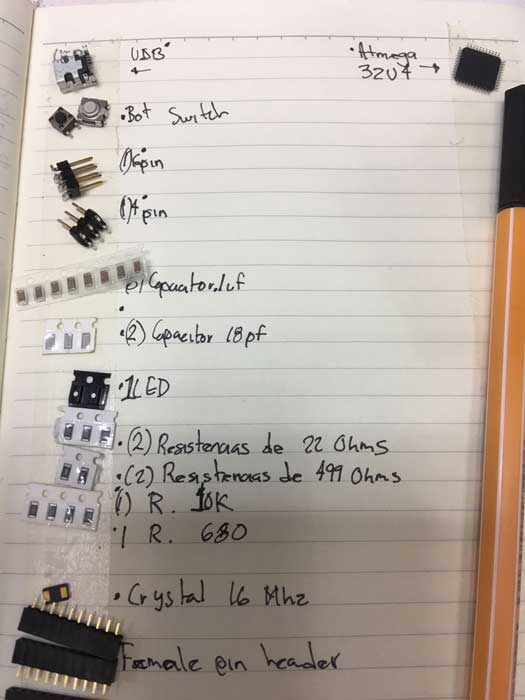
For the components i will need:
8 Capacitor .1 uF
2 Capacitor 18 pF
2 Leds
2 Resistor 22 ohms
2 Resistor 499 ohms
1 Resistor 10K
1 Resistor 680
4 Resistor 1M
2 Female Pin header 8x1
Crystal 16 Mhz
1 ATMEGA32u4
1 Switch
1 Female pin header 5x1
1 Male Pin Header 2x2
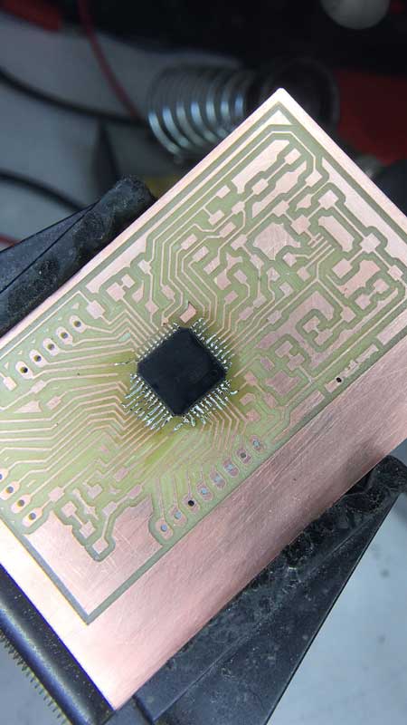
A lot of people told me that soldering the ATMEGA would be difficult but for me it wasn't so complicated, I mean it was, but i had worst problems that this. When i sent my detail file, I did a wrong file and it did the details but it cut the traces that connect with the pins of the ATMEGA , so it was more difficult to do the bridges that connect again the traces than soldering the pins.
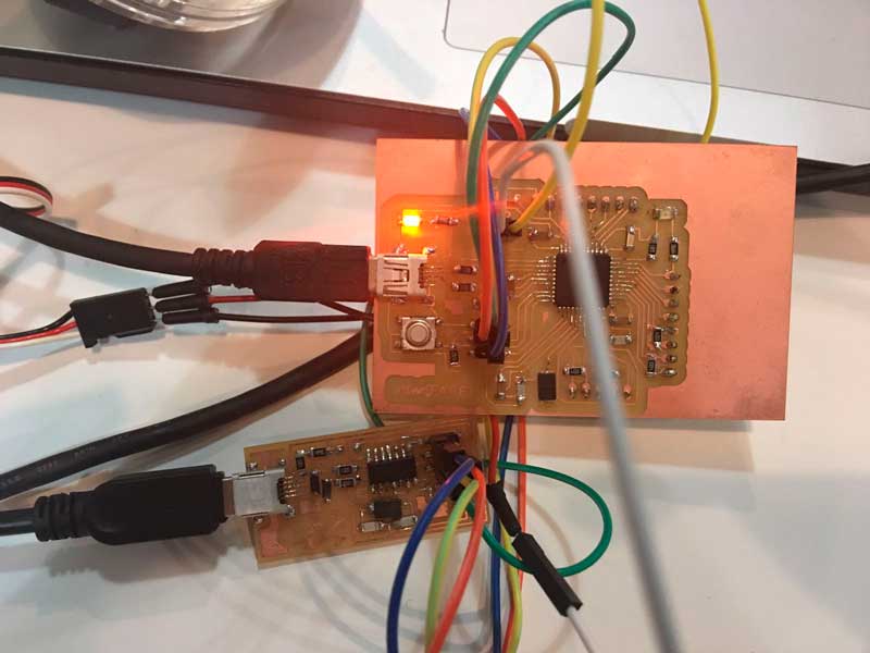
Here is everything soldered
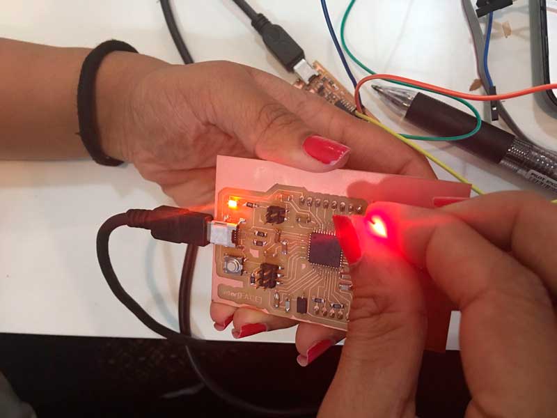
Here I'm trying to programme my board with the AVR ISP and it seems everything its ok because the light is green when i connected it
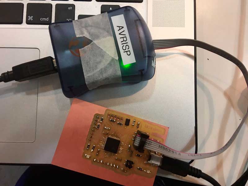
Even Though the light was green, when i tried to program it in Arduino, it appears an error all the time with the clock. I researched on internet how to solve the problem but it seems it is something wrong with the programmer, the ATMEGA32u4 is not compatible with the AVR ISP. I ask to my classmates and some of them have the same problem, and they toldme they solved it only changing the AVR with the USBTiny programmer that we did before.
I found this diagram in other fab academy page, where you can see the number of the pins, So now i can convert the number of the pins that I'm using now from the Arduino Mega to the pins of the atmega32u4.
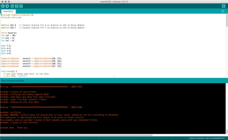
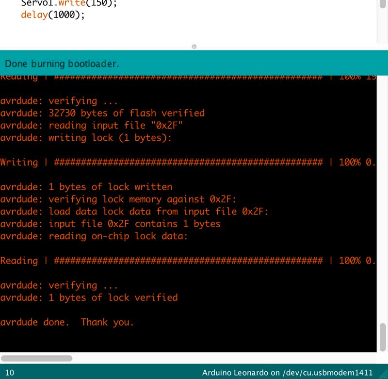
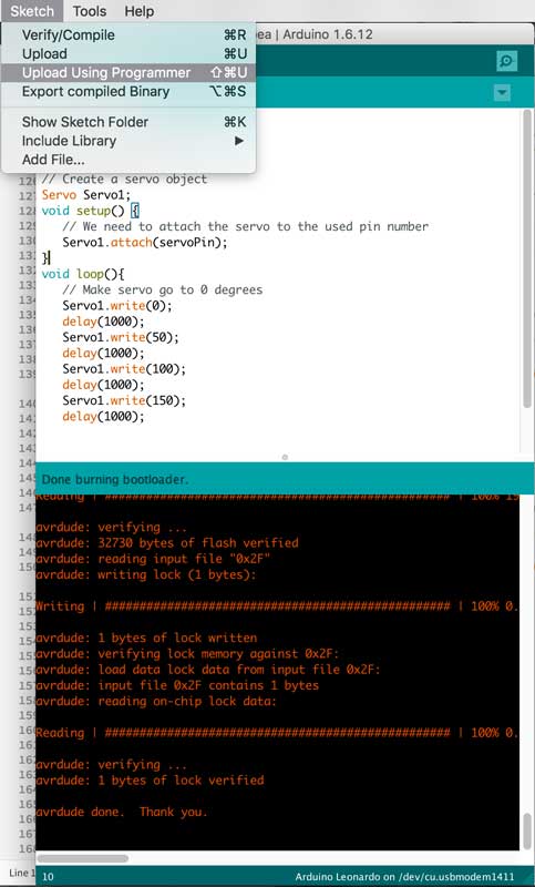
Here i could do the burnloader with the USB Tiny
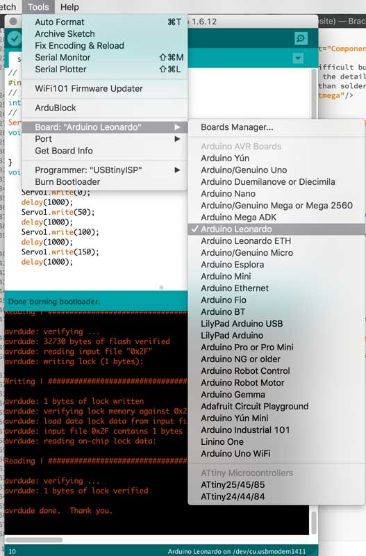
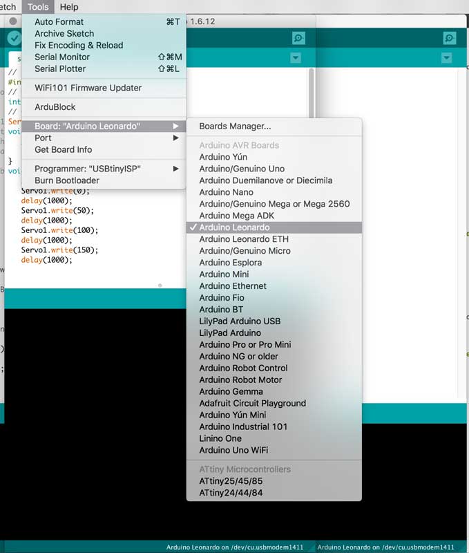
At the beginning if i want to upload a program in my Arduino Leonardo, i had to have connect the USB TINY every time i want to run a different code. Like this.
Because if i disconnect the USB tiny it was impossible to upload the code, but one day before the final presentation, One of my tutors told me that this could happen because my soldering is not good in the USB component, so fix this and now it works perfectly but its own.
First i programmed a LED, then my servo valve, and finally all my program for my final project.
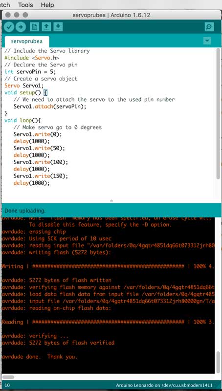
Mask working with Arduino Leonardo
Final Code
The dead line for the presentation in the Fab lab Barcelona is on 16th of June. I have more less two weeks for still working. I started with the electronics and i had a lot of problems fabricating my own Arduino, but finally I could do it. I still have to work on the fabrication of my mask because i want to resolve the process of the fabrication in some steps that are not the best until now, like the integration of the nicrome wire. In every step i tried to think how would i resolve a masive fabrication of my mask, and this one I have to fix, i was thinking that maybe i have to fabricate as an extra a machine that bends the wire, that i should integrate in the mold if the mask a path where I only have to put inside the wire, etc. A lot of work to do yet.
The electronics are the hardest for me, i have to make it work, the code for the mask I have it already since one month ago with the commercial Arduino Mega, but not with my Arduino Leonardo. Also, i had problems traying to integrate the changing color layer with the Air layer in the mask, and until now I have it but separate that make me waste a lot of time, I though it was going to be easier but not, so I'm not sure if I will be able to get to the sistem integrations step.
I've made a plan. I made a list of the remaining tasks for the final project and also I've choosed some of them for the next step, for example the cold water for reversing the color change, I will not have time to work in this step. So first I will work in the most important thing I haven't finished, the electronics, then the integration of the different layers of the mask and finally I will put the finals informations for my final video.
The code for the dynamic of the mask, this was the easiest but maybe it is because i did it a month ago.
Now that i have less time, I'm not sure to finish the integration of all the functions that i want for my mask, now they are not working toguether, they are only working separate.
Could this prototype work for the actual market?
Will this prototype be success for Kick starter campain?
How will I design a wearable system for make the autonomous prototype?
In the case of success, how will i be able to do the massive fabrication?
Would this be usefull for the real society?
I learnt a lot about fabrication of non conventional prototypes, I mean the soft robotics, For me is clear that what I did wasn't the most complex example but now i feel that there other ways to resolve things with other methods. After practicing a lot of programming and I feel prepare to use other kind of codes besides Arduino. But the step that i learnt a lot was the electronics, I still have a lot of doubths but now I'm really interest to resolve my own questions because i really want to feel sure and in the future I can improve and make my own electronic boards. I'm very happy because, eventhough i didn't finish what i wanted it, I enjoyed learning a complete new things in a prototype that I wanted, this time the limitations were the electronics and the soft robotics but now that I know more, I'll work on this until i have all the things that i want to integrate.
In total i have spent like 152 euros, the most expensive thing was the thermochromic additive. Everything else i found them in the Fab Lab.
ECOFLEX 40 EUROS
NICROME WIRE 5 EUROS
THERMOCROMATIC ADDITIVE 20 EUROS
ACRILIC 20 EUROS
AIR POMP 10 EUROS
PIPES AND CONNECTIONS 5 EUROS
POLYPROPYLENE 5 EUROS
CARDBOARD 20 EUROS
ELECTRONICS 27 EUROS
//Ilustrator
//Photoshop
//Rhinoceros
//MAYA
//123D MAKE
//Fritzing
//Eagle
//Arduino
//Processing
//Fab Modules
//PYTHON
| Fab Academy 2017 | Fab Lab Barcelona | Trinidad A. Gomez Machuca |
| IAAC | trinidad.gomez@iaac.net | |