

Codifying personal data into a hardware interface instead of decodifying reactions based on physical aspects.
Final project. Fab Academy 2017 at Fab Lab Barcelona By Trinidad Gomez Machuca
Wikipedia says that Soft Robotics is the specific sub-field of robotics dealing with constructing robots from highly compliant materials, similar to those found in living organisms. [1] Similarly, soft robotics also draws heavily from the way in which these living organisms move and adapt to their surroundings. In contrast to robots built from rigid materials, soft robots allow for increased flexibility and adaptability for accomplishing tasks, as well as improved safety when working around humans.[2] These characteristics allow for its potential use in the fields of medicine and manufacturing.
I really think that soft robotics are fascinating, i want to learn how to control one. But honestly i want to learn how to make this is because I'm planning to do other projects with a comertial porpose and As you know all academies projects has to be open source so it will be a good exercise to practice now.
Here you can find some links that i followed to understand this kind of robots.
Soft robotics Air power Example from Instructables
Soft robotics Examples from Instructables
This is my plan, for my final project I want to program a interface in python or processing that will show in real time data the information of my inputs. Then program all the hardware in arduino and when i understan well I can do my own board, and fabricate the mask with the same material for the soft robotics, the ecoflex, only if I have time I'll try to do it with a bio plastic.
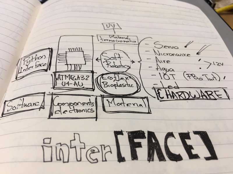
For the fabrication I will need only the ecoflex combined with thermochromic dust that will allow to change the color of the ecoflex depending on the temperature. I will do the mold in the CNC or the 3d print.
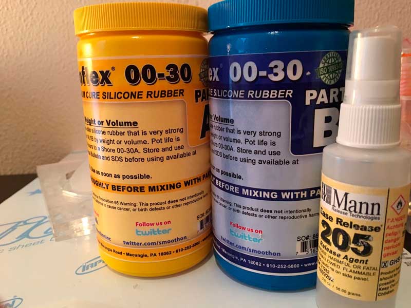
Ecoflex 00-30 the ecoflex is the most flexible, I researched what kind of material and the most common one was this kind the 00-30.
Thermocrhomatic aditive. This material is expensive and hard to find but it is very cool to try.
Nichrome wire this one you can find it in a Stationery, is commonly used for cutting foam materials, depending on the volts that you used can be very hot and cut or only change the color of my ecoflex.
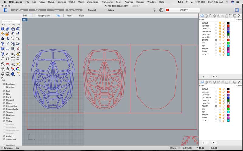
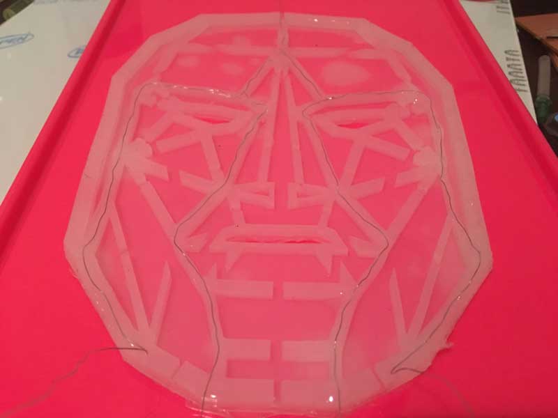
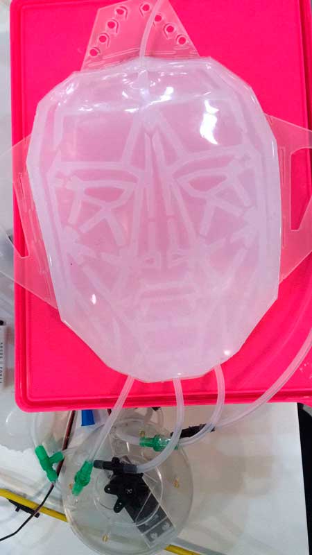
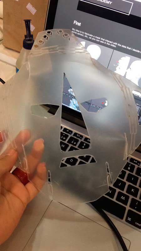
First, I started fabricating the mask with the ecoflex. I used the same draw that I did for the input device in the capacitive sensor. Honestly I was planning to work in a different design for the mask, but now i only have one month left, and i starting getting nervious, so I let the same design, so now i can concentrate in the fabrication of the mask. Here in the picture below you can see the design of my mold, ecoflex works perfectly in plastics so i decided to do it in acrilic, so i draw my base with the engraving of my final design, the middle one is going to be the place where the air is going to enter and the empty spaces is going to be filled with the ecoflex and the last one in the left is going to be the seal layer but in the using the same base but in the other side of the acrilic, so at the end I will have two molds in one piece.
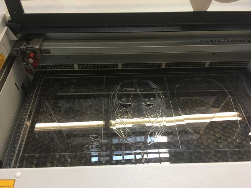
Here you can see how I laser cut my mold.
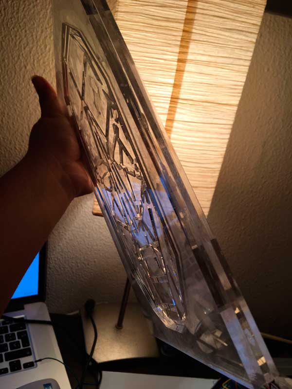
Here you can see the result, the right one is the base, the second one is the mold of my draw and the last one is the mold of the seal layer.
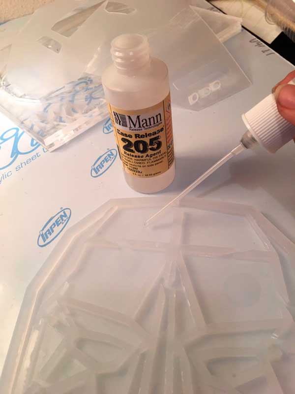
Before to start with the soft robotics, i researched that the best material for doing this is the Ecoflex 00-30, is the most flexible and clean material, besides is very easy to make the combination of the material, the proportions are 50-50 and you only need to mix it very well for 5 minutes and that's it.The other one, is recomended for putting over the excoflex material when this is dry, you put a lot of layers of the liquid. This one doen't allowed to stick between two thin layers of ecoflex.///////////////////////
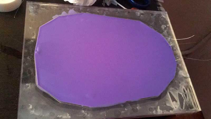
When the two part of the ecoflex are dry, i put this liquid very cafully in the area where I'm planning to put the air so i Can inflate it, as you can see in the image, i put this in the inner areas.///////////////////////
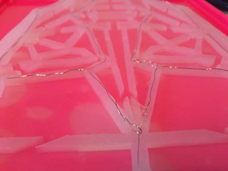
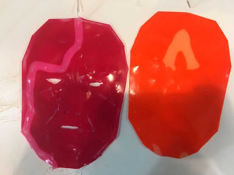
After join the pieces, I put the silicon, in this case in the video you can see how i put the silicon combined with the thermochromic additive, the one that is going to change the color with the heat. My mold is a bit confusing but this is the side of the seal layer.
After it dries, I put silicone in the other side and you can see how easily I took it out from the mold, the acrylic make very beautiful and clean soft robotic mold.
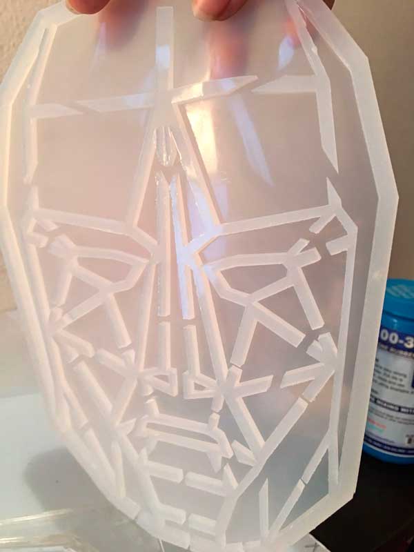
Here you can see the seal layer.Here you can see, when i touched it, it change a bit in the color.
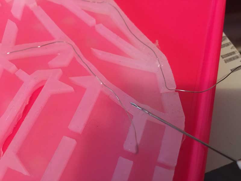
After that, I was confused because i didn't plan in with part of my fabrication process i was going to introduce my nichrome wire, so in my first try I did it manually, I sew the wire very carefully until it get in the position that i wanted, it doesn't look nice but if was the only way i could think in that moment. I had a lot of troubles, because when I was traying to seal it, the surface wasn't plane, I did it like two times and it didn't seal in the inside. So now I have to think how to put the wire in a different way.
Here you can see in the video how I joined the two parts of the mask with the wire inside, but unfortunately I didn't work, the two layer stick each other, some of the part didn't get together so when i tried to put air inside, It didn't do properly. BIG FAIL
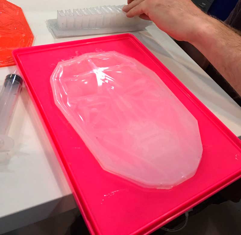
I was stressed because the mask did not work properly so i decided to do one, that works only with air, I did it very carefully. I forgot to say before but when you are using ecoflex for the soft robotics, there is a special liquid that doesn't allowed to stick two layer of silicon, so I used it a lot. I put this liquid in the air areas, It smell horrible but it works perfectly. This liquid is very dangerous so be carefull if you are planning to used it and also, you have to put it a lot of times, wait to dry and put again, and so on. This works!
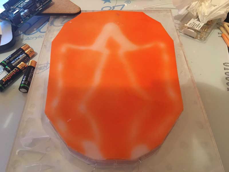
Before to start with other part, even the mask is not working with the air and heat together, i put the layer with the thermochromic additive with the wire just down of it, and I connected it with 12 v energy, as you can see it change the color, with cool temperture is always orange and with the heat it changes to white. Everything was great until I stop the energy and I realized that 12 v is too much for the material, it didn't burn it but, besides is dangerous in the face the temperture that i got, the additive didn't work anymore, so i need to try with a lower voltage.
After one hour without heat, the material didn't go back to its colorful state. It's burned.
The last one before the final presentation. Hope it works.
////////////////////////////////////////////////////////////////
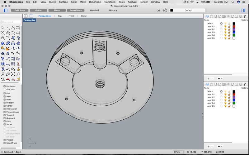
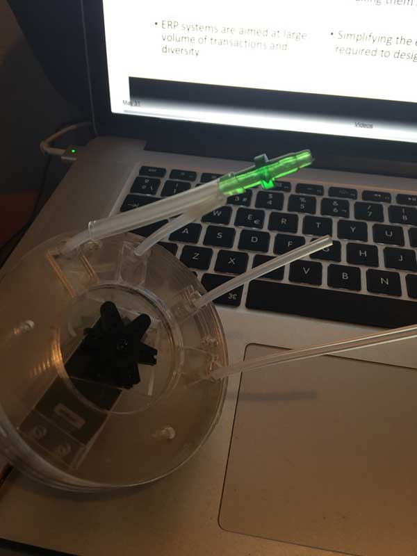
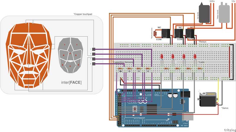
In this part i started to fabricated a servo valve, I didn't designed by my own, two years ago we invented it in the lab where I work togeter with my team and one student for a contest, We won a international award in Brazil, but in that time we invented it for a litle irrigation sistem, only three channels of water. I decided to used it because i need to use one air pump but i need to inflate 4 parts of the mask, so instead of buying 4 pumps i change the design of the servo valve for four outputs.
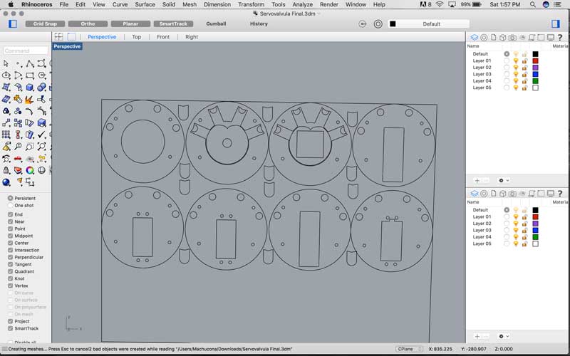
It works like this, when you touch a capacitive sensor, then, first will open the relay and it will activate the air pump, after it will trigger the servo motor, this one will move to the correct angle, in the channel selected, the capsule will be down so it won't press the pipe allowing the air to pass, so this pipe will be connected in the area that you select in the draw of the copper that works with capacitive sensors.
.
In the video below, you can see how it works, I had a lot of problems because I didn't found the proper and flexible hose, the capsule wasn't pressuring enough, so the air was flowing in the four channels. I did a lot of changes, resizing, but when it finally pressed the hose, the servo didn't move because it was a lot of pressure inside, besides when i bought the motor, i confused the type. I needed a servo that respond to the angles not the continous rotation.
Here I attached to the servo all the pipes, as you can see this is the system that i will need with the connections.
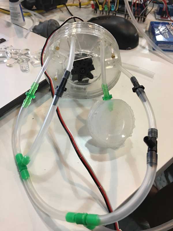
And here is how i connect the pipes system to the mask, every area has one pipe, let's see how it works.
After i finished the the servo mask with the ecoflex, i realized that it is very uncomfortable to have this material over the skin, besides, I didn't think how to attached the mask in the face, So I designed a mask that holds the ecoflex mask. The design was made for attach to the ears and has holes where will pass the hoses.
Is a basic mask but it works for the purpose I've designed it.
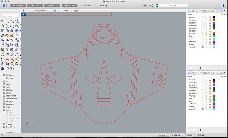
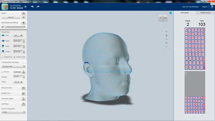
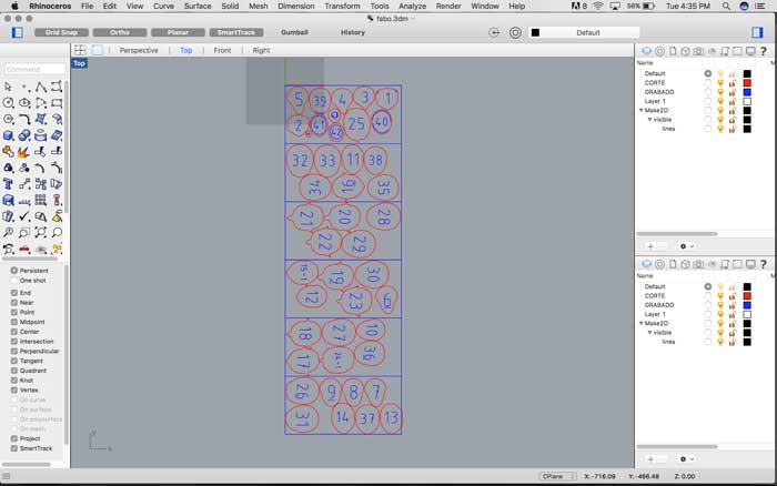
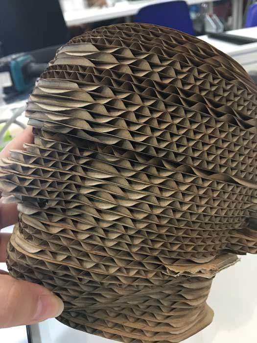
In the last minute, I fabricated a Head for my mask, in 123D MAKE, I only cut the model of a body that i had , and then export it in this program, and the good thing is that it makes automaticly the files for laser cutting.
Fab Academy 2017 at Fab Lab Barcelona By Trinidad Gomez Machuca
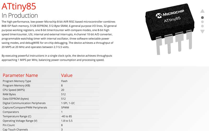
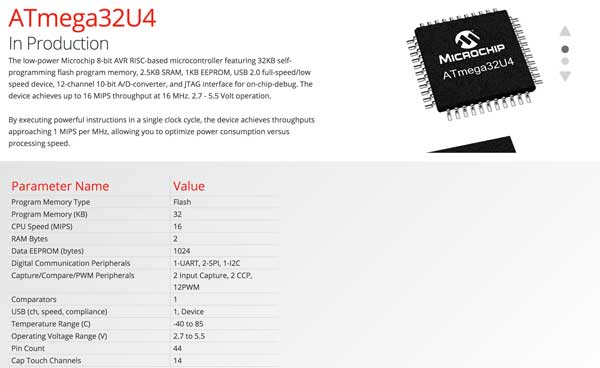
When i was doing my input device assignment... I fail, but i've learned a lot about the properties of the microcontrollers. First before to choose a microcontroler, you have to know how many data you will store. In the input assignment i choosed to do a touchpad, for this you have to use capacitive senros. I you want to progam it in Arduino you will need to install the capacitive sensor library, this is the only way you can see if your sensors are giving you back in the serial port. But in the example that i was following they use a attiny44 microncontroller, a library and the code it was too much information for this attiny. So at the end i have to follow the same squematic but with other attiny. I followed Attinny44 datasheet, Attinny85 datasheet, and so many until i found the right one. For the time i want to pass directly to applied the capacitive sensor in my final board, with i will use a atmega32uf, the best one for doing a lot of task, at the beginning i wanted to used only for capacitive sensors but i realized that is a very powerful microcontroller that it will be a waste if you only used for this.
This is one of the reasons that i did all my circuit in the Arduino Board first, so i can know how many bytes i need to run all my code. You can know this information when you compile your code in Arduino, at the end it shows how many bytes you are using, so depending on this, you can choose a micro controller.
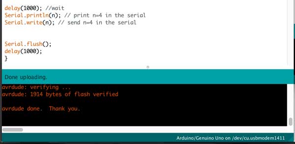
And here you can see how many bytes this microcontrollers can store, in the RAM bytes.
So before to start doing my own board for my final project i decided to do it first in the Arduino mega, So i can understand for complete how everything is connected and the also i want to understand all the code. I did not know a lot of things, like how the relays works, how to connect a nicrome wire, how to put capacitive sensors in the Arduinodirectly, etc. so it was good to do this because now I know and I think is very easy to do it, so I hope i can do it in my final board. After i finished to connect everything, I made this Fritzing/Illustrator diagram.
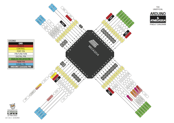
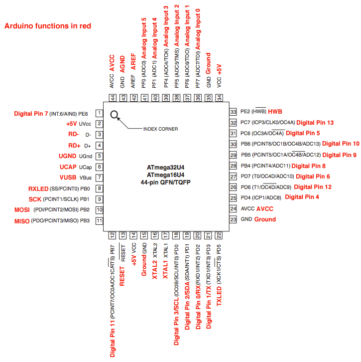
For starting to design your schematic design of your microcontroller in Eagle, you need this kind of data sheet where you can see the pins and change it when you pass everything to your own board. The number of the pins always change from the arduino board to the other microcontrollers. For example if in your Arduino code and board your are using the A1, if you are using a attinny44 you should look the pin number equivalent. As you can see in this diagram, it shows the equivalent pins in Arduino.
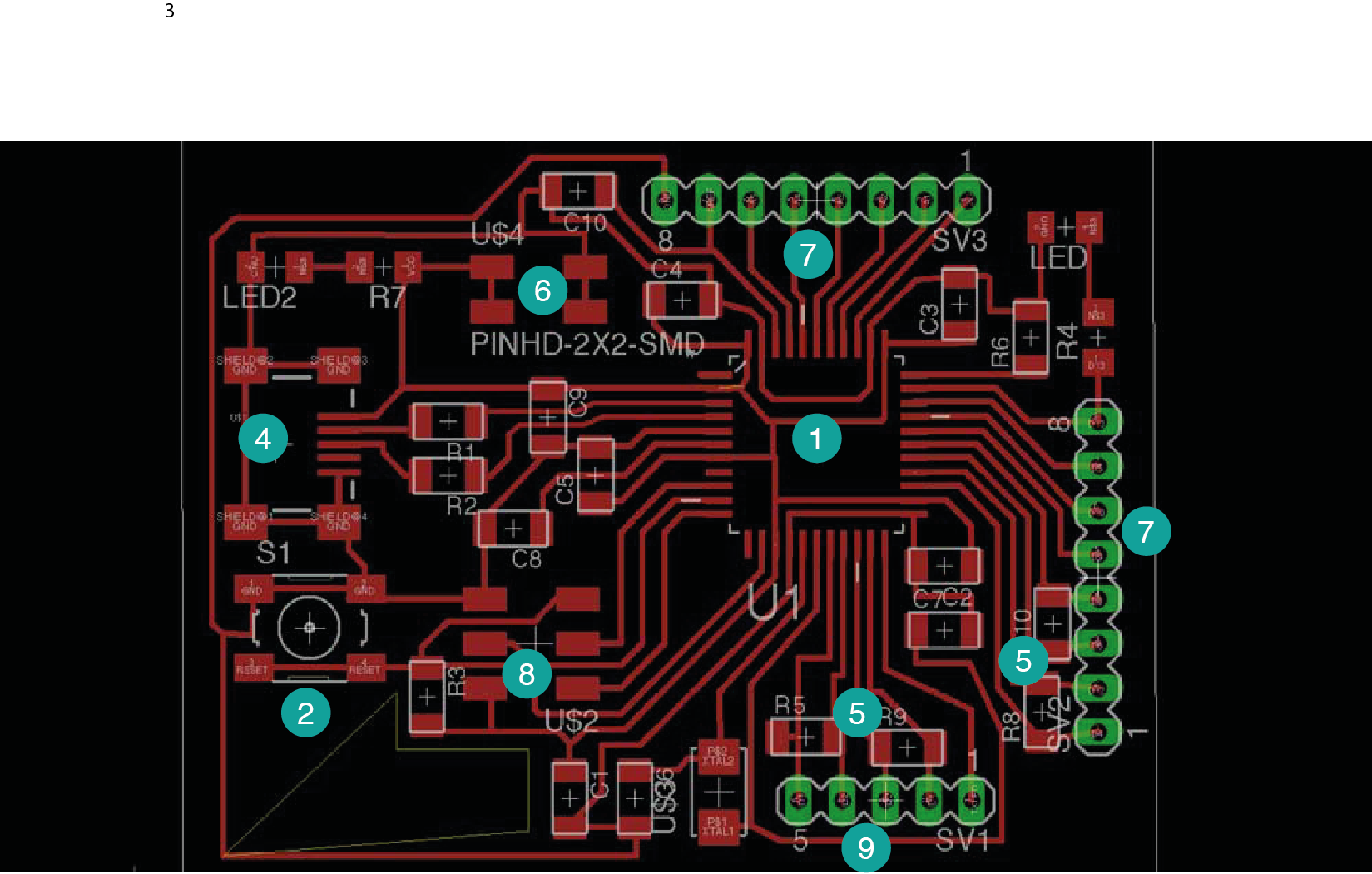
1- Here is the ATMEGA32u4
2- Here is the switch for the reset
3- Capacitors
4-Here is the system for the usb programmer
5- Here is the capacitive sensors for the pins
6-Here is for the external energy, I didn't add a voltage regulator, so here can only be 5 v, if you connect more energy, the ATMEGA can be burn.
7- Here is for connecting digital and analog pins.
8- Here is the AVRISP programmer
9- More digital pins
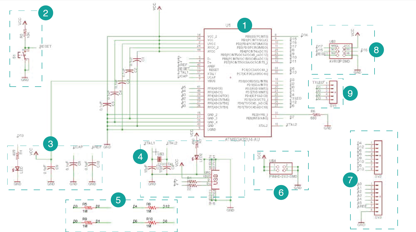
Here you can see in the board how a order my components in Eagle.
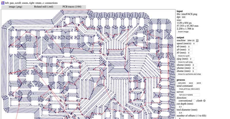
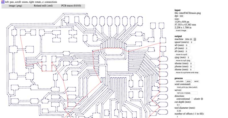
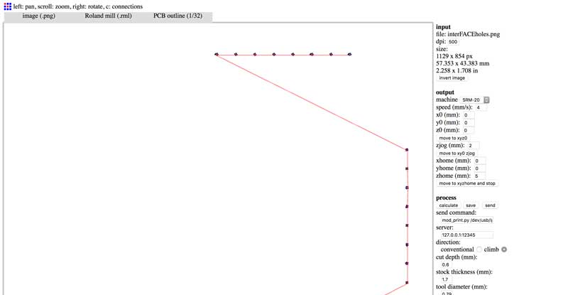
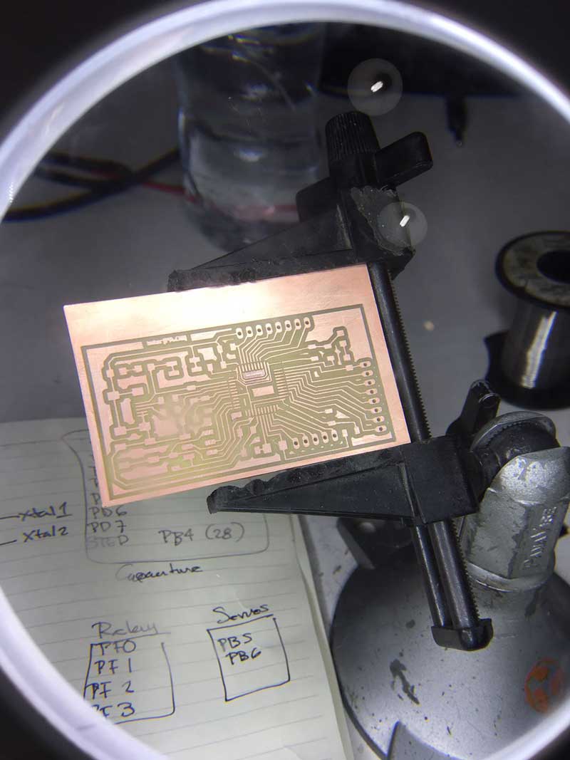
Here are my png files for the modella machine, The first one is going to be for to the 1/34 drill that is for traces, and the 0.01 is for the details that the ATMEGA34u2 need. First one the colors are invert, background should be black. The second one is for the holes, this one has the correct colors.
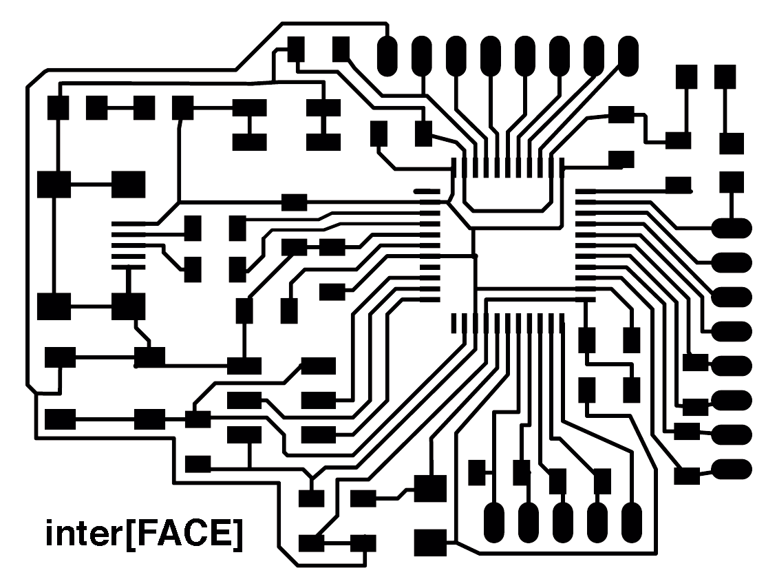
Here I'm using Fab modules for converting the files in c code. So here you can see how the machine is going to follow the path with the different drill bits. Here is very important to make the details with the 0.01 drill bits other wise you will have problems when you solder the Atmega because the 1/64 can not do the tiny details, the only thing that you have to do is use the same file for traces but change the settings in the Fab modules.
Here is the board milled, so now i will start soldering.
FAILS
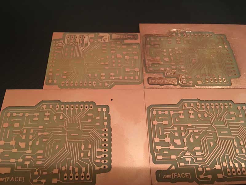
Three weeks before the finals, I was trying to fabricate the Arduino Leonardo, the first one worked the milling, but not when I solder it, I couldn't do the bootloader in the Arduino, so i did it 4 more times and always something happened, the traces too thin, some were broken, or the last one it was a perfect one until it finish the holes, it went back to the start point but the drill didn't go up, so it broken all that ii was in its way, I lost one week just trying to milling, so I hope my board works in the last week of the academy.
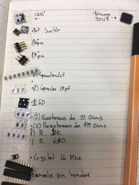
For the components i will need:
8 Capacitor .1 uF
2 Capacitor 18 pF
2 Leds
2 Resistor 22 ohms
2 Resistor 499 ohms
1 Resistor 10K
1 Resistor 680
4 Resistor 1M
2 Female Pin header 8x1
Crystal 16 Mhz
1 ATMEGA32u4
1 Switch
1 Female pin header 5x1
1 Male Pin Header 2x2
A lot of people told me that soldering the ATMEGA would be difficult but for me it wasn't so complicated, I mean it was, but i had worst problems that this. When i sent my detail file, I did a wrong file and it did the details but it cut the traces that connect with the pins of the ATMEGA , so it was more difficult to do the bridges that connect again the traces than soldering the pins.
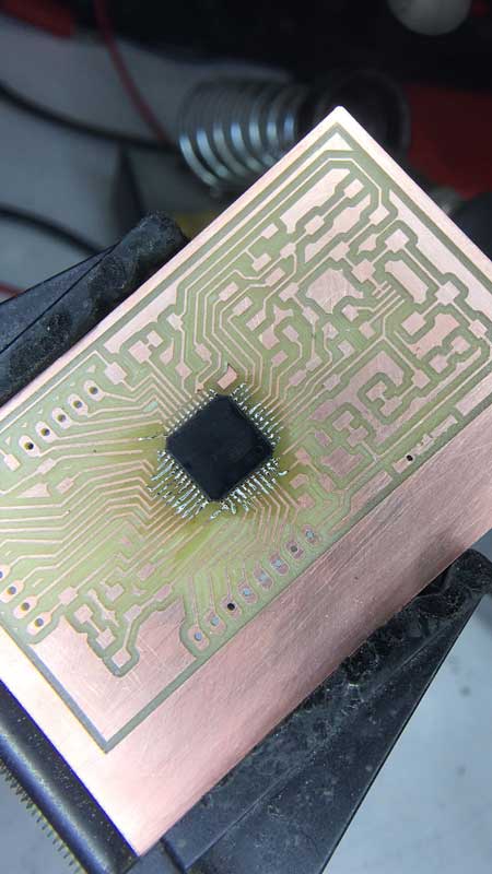
Here is everything soldered
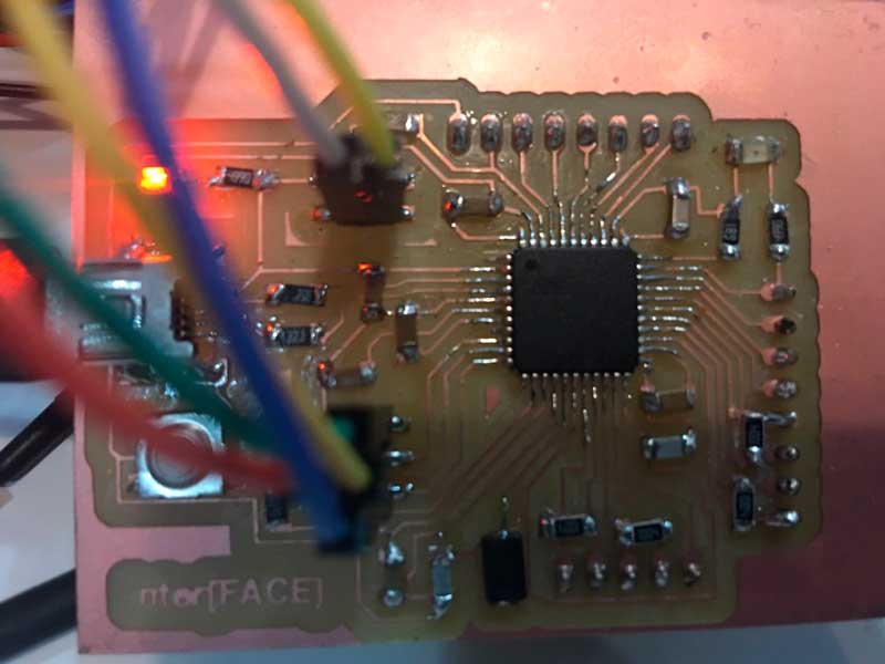
Here I'm trying to programme my board with the AVR ISP and it seems everything its ok because the light is green when i connected it
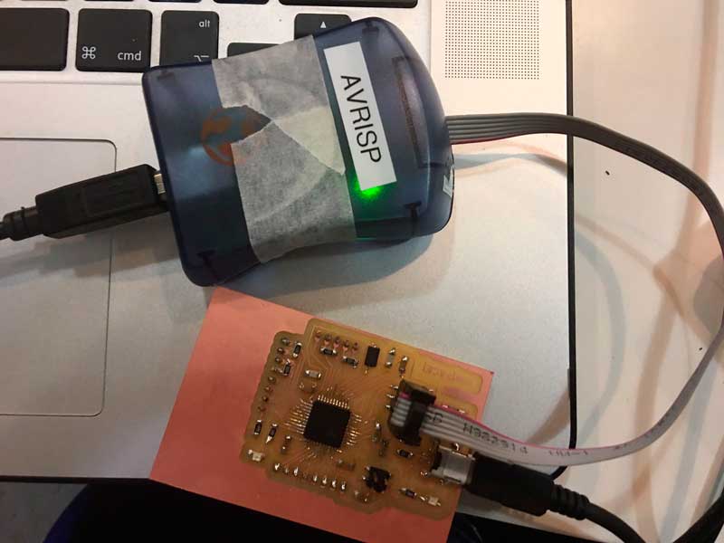
Even Though the light was green, when i tried to program it in Arduino, it appears an error all the time with the clock. I researched on internet how to solve the problem but it seems it is something wrong with the programmer, the ATMEGA32u4 is not compatible with the AVR ISP. I ask to my classmates and some of them have the same problem, and they toldme they solved it only changing the AVR with the USBTiny programmer that we did before.
I found this diagram in other fab academy page, where you can see the number of the pins, So now i can convert the number of the pins that I'm using now from the Arduino Mega to the pins of the atmega32u4.
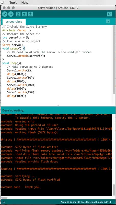
Here i could do the burnloader with the USB Tiny
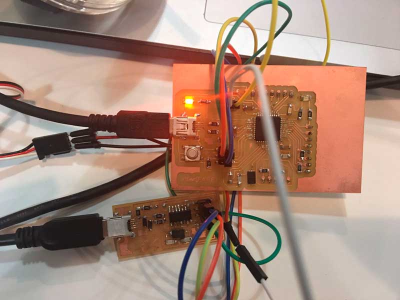
At the beginning if i want to upload a program in my Arduino Leonardo, i had to have connect the USB TINY every time i want to run a different code. Like this.
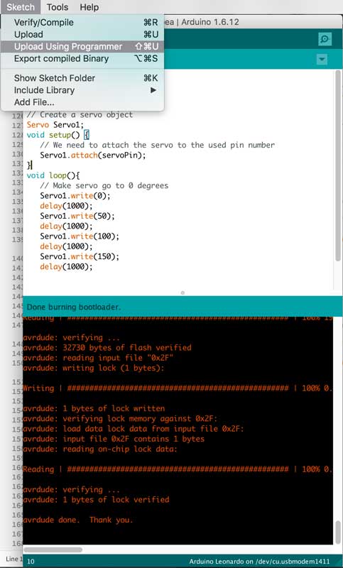
Because if i disconnect the USB tiny it was impossible to upload the code, but one day before the final presentation, One of my tutors told me that this could happen because my soldering is not good in the USB component, so fix this and now it works perfectly but its own.
First i programmed a LED, then my servo valve, and finally all my program for my final project.
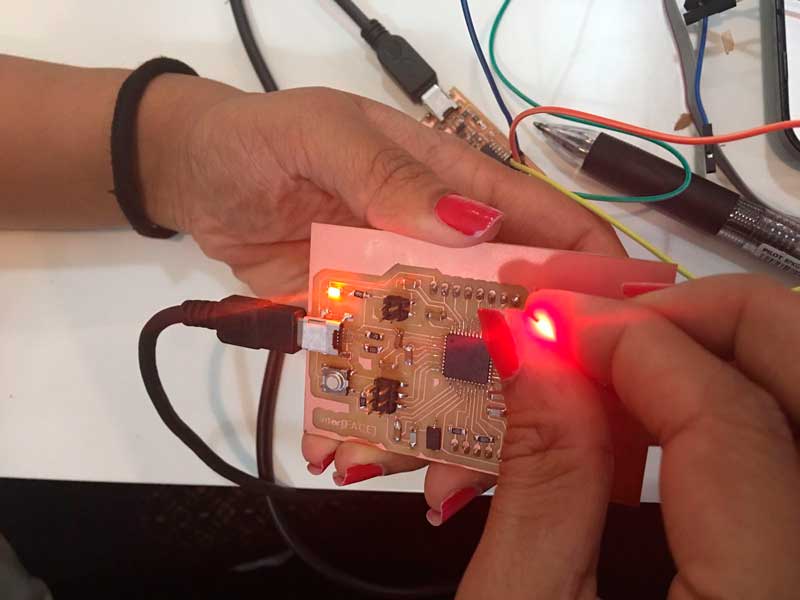
Mask working with Arduino Leonardo
| Fab Academy 2017 | Fab Lab Barcelona | Trinidad A. Gomez Machuca |
| IAAC | trinidad.gomez@iaac.net | |